

Coopra 15B, 30C, 15C, 30B, 40C User Instructions
...
User instructions……………….. EN
Bedienungs-Anleitung.……....... DE
Bedieningsvoorschrift………..... NL
15B - 30B - 15C - 30C - 40C - 30K
N000129074 - User manual 15_30_40 - EN_DE_NL - RCB050404
N000129074
User instructions
Central heating unit (suited for external cylinder).…………..15B
Central heating unit (suited for external cylinder).…………..30B
Central Heating Boiler (heating)...…….…………..…………..15C
Central Heating Boiler (heating)...…….…………..…………..30C
Central Heating Boiler (heating)...…….…………..…………..40C
Combi-unit (central heating + hot water).…..............………..30K
General
The unit combines a maximum of comfort with an extremely
easy operation.
As the user, you need do no more than set the desired
temperature on the room thermostat, no matter what time of the
year.
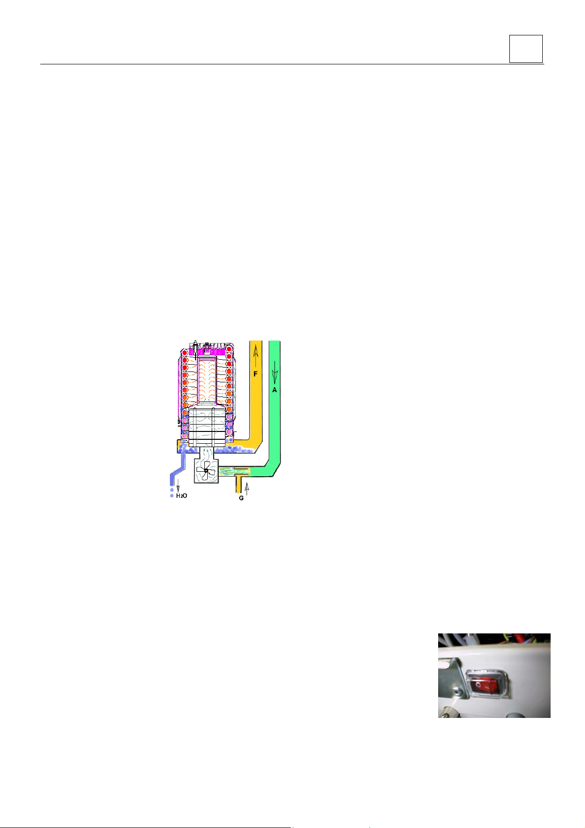
How the boiler works
A fan sucks the air required
for the combustion through
the air feed canal (A).
Because the combustion air
in the venturi sucks an under
pressure, the correct amount
of gas (G) is automatically
added to the combustion air.
The flammable gas/air
mixture thus obtained is fed
to the burner, via a mixing
chamber, to be ignited at the
surface of the burner by a
ceramic glow plug. The hot
combustion gases are
efficiently fed through the
heat exchanger, where they
give their heat to the water.
The flue gases are fed outside, through the flue tube (F), into a
flue tube exhaust canal.
The condensation water (H
the sewer.
Burner is on
• when the room thermostat is closed (heat demand)
• and when the actual flow temperature is 5°C below the set
point (desired heating flow temperature)
• and after 3 minutes anti-reciprocital time, if applicable, after
a reciprocital stop
Burner is off
• when the room thermostat is open (end of heat demand)
• when the actual flow temperature is 3°C above the set point
(blocking)
• or when the actual flow temperature is 3°C above the
maximum permissible central heating temperature.
O) thus obtained is discharged into
2
User instructions 15 – 30 – 40 EN
Tips
Depending on how much you value optimum comfort and the
lowest possible energy consumption, the following tips can help
you make optimum use of your unit:
To help limit the energy consumption, it is recommended to set
the room thermostat to a lower temperature a few hours before
going to bed.
Turn all radiator taps fully open in the rooms that you want to
heat.
Shut the radiator taps off in the rooms where you do not want
any heating.
Cleaning the unit
Regularly clean the outside of the unit with a soft, damp cloth. It
is not necessary to shut the gas tap off or switch the mains off
for this.
Never use aggressive or flammable cleaning agents.
Take note that the pipes can be at a high temperature.
Holidays
With long-term absence, for example in the holidays, it is
recommended to leave the unit continually switched on. The
reason is that the unit makes a number of checks every 24
hours.
If frost can be excluded, set the room thermostat to a lower
temperature.
If frost cannot be excluded, set the room thermostat to a
temperature of 12°C or higher.
Although the unit has an internal frost protection, this does not
protect the whole installation against freezing.
Brrrr, the central heating is not working
In the unlikely event that the central heating has let you down,
we have some tips for things that you can check and remedly
yourself before an installer.
The central heating boiler is a fairly complicated item that is
fitted with safety devices, which
prevent a dangerous situation.
There can be many reasons why
the central heating is not
working.
Electricity and gas
Is the connection of the green
block in the green socket correct
connected?
Is the main switch on the unit in the right position?
Or is the circuit to which the boiler is connected out of operation
because the fuse has blown or the earth leakage switch has
activated?
2
Is there an (unusual) interruption in the gas supply? Check by
seeing whether a gas cooker in the kitchen is working. If it is not
working, call the gas company. The gas flow can also be
blocked because the gas filter of the boiler is contaminated; this
is a problem for the service man.
The unit also lets the pump regularly run outside the heating
season to prevent it from sticking. If the mains supply outside is
interrupted several times during the heating season, the pump
can stick. Solution: turn the shaft of the pump a few times by
hand (screwdriver).
Water and air
If the water pressure in the installation falls below a minimum
level, the burner will be off.
Solution: Top up with water.
It is possible to read the water pressure directly from the
display.
Reading: Press the + button in for a minimum of 5 seconds.
From the menu back to normal operation: Press the - button in
briefly (or automatically after about 5 minutes).
During filling, the unit must be connected to the mains and be
switched on.
Fully open all radiator taps.
Connect the water supply to the filling connection of the
installation.
Open the tap to fill the system with water.
When the water pressure is sufficient (> 1.3 bar), close the
filling tap again.
If there is air in the installation, the boiler can switch on, but the
radiators remain cold.
Follow the instructions from the manufacturer/installer for the
venting of possible other elements of the heating installation,
such as floor heating.
Fully open all radiator taps.
Vent the radiators after the pump is switched off.
Open the air bleed cocks of the radiators one at a time. Use an
air bleed key for this.
As soon as water comes out of the air bleed cock, shut the cock
off again.
If the central heating boiler is at the highest point of the
installation, air can collect in the boiler. This can cause a
malfunction in the boiler. Also vent the internal tap pot (only with
a Combi-unit).
Other causes
There must be heat demand from the room thermostat or other
control, otherwise the boiler will not switch on. Set the
thermostat to demand heat and check whether the boiler
switches on; this can take a minute or so.
If there is little water circulation because too many radiator taps
are closed, the boiler will not function or will function
insufficiently. In this case, open more radiator taps or ask your
installer to fit a bypass valve.
User instructions 15 – 30 – 40 EN
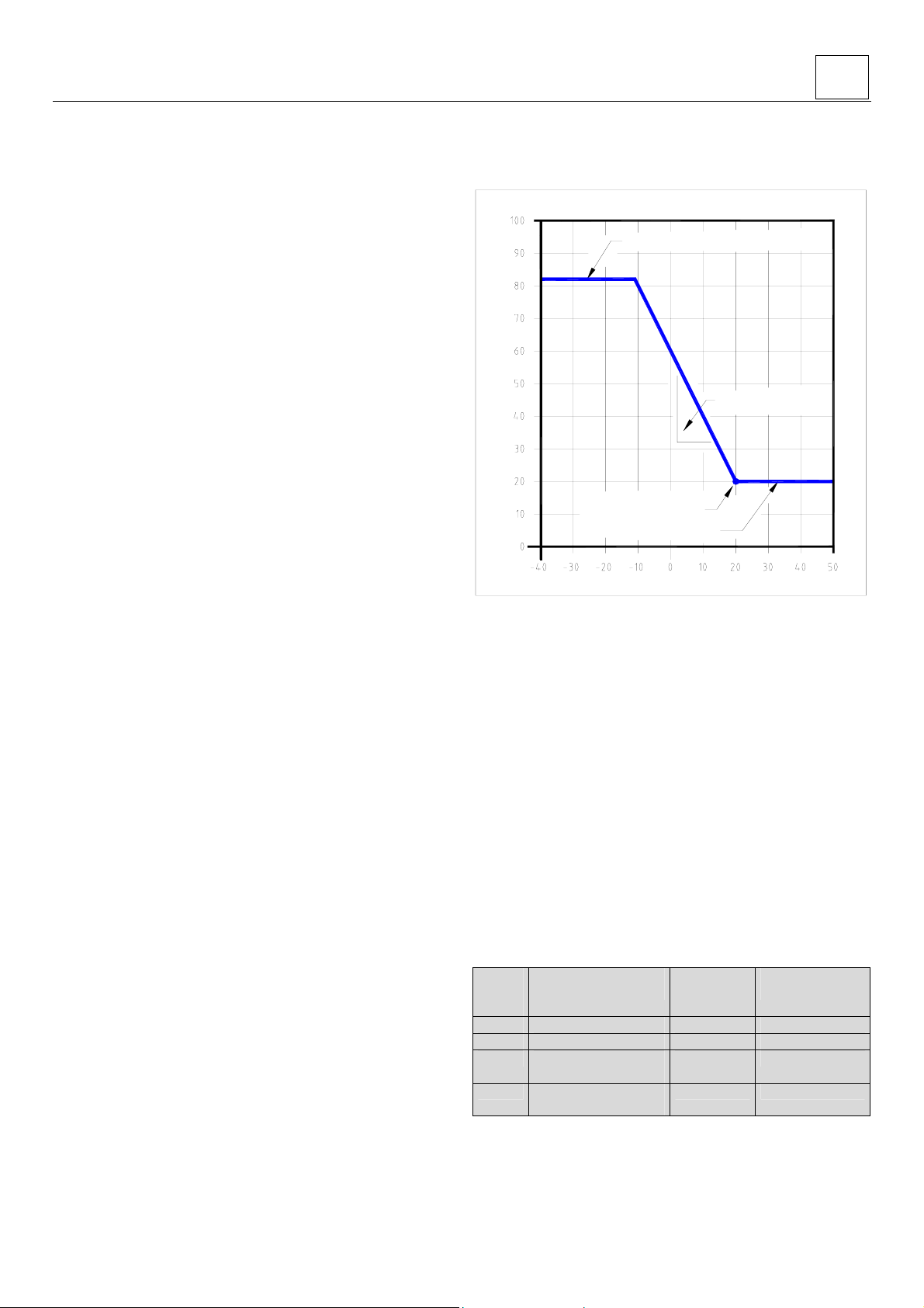
Adjustment heating curve
( in case of an outdoor temperature sensor)
Parameter C=82°C [default]
Supply temperature [°C]
O/S=20 [default]
O/d=20°C [default]
O/b=20°C [default]
Outside temperature [°C]
Adjustment
By pressing the set/reset button in for longer than 5 seconds,
you go to the ‘mode’ menu.
To change the subsequent "Letter in menu" parameter, the user
must press the Set/Reset button.
To change the “Range” setting in the parameter, the user must
press the “+” or the “–“ button.
O/b-value: The setting of the minimal Heating flow temperature
( value in °C).
O/S-value : The setting for the sloop of the curve.
( change of Flow temperature depending on the change of the
outside temperature).
O/d-value : The setting of the flow temperature at an outside
temperature of 20°C ( value in °C).
Parameter „C“
The setting in the menu „C“ makes the maximal heating flow
temperature ( default 82°C).
Letter
in
menu
O/b Basic temperature 10 –70 °C 20 °C
O/S Slope 1 – 100 20
O/d Flow temperature at
outside = 20°C
C Max. Flowtemp. for
heating
Description
Range
default
0 –70 °C 20°C
25 –90 °C 82°C
3
User instructions 15 – 30 – 40 EN
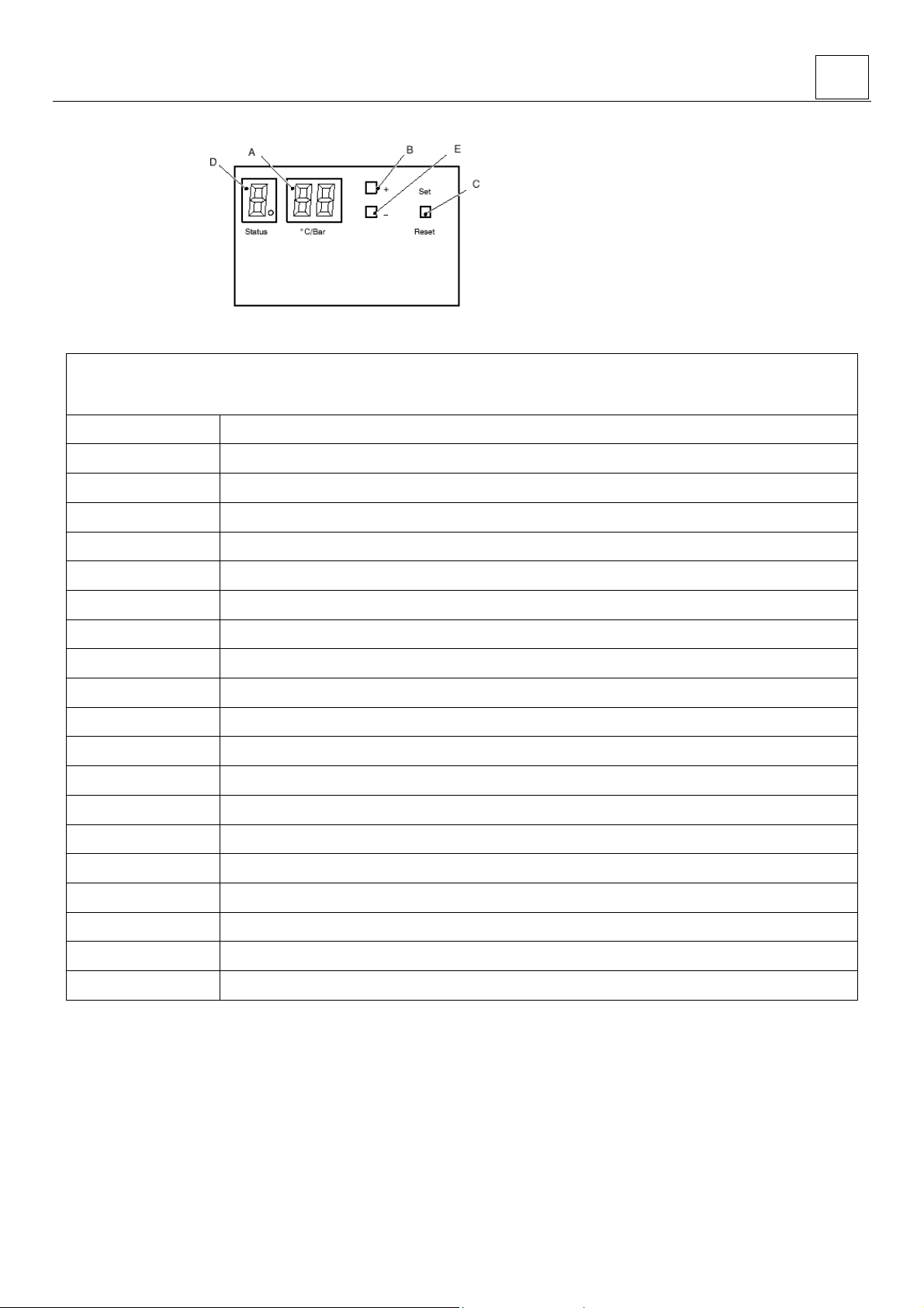
Display
A = display
B = + button
C = Set / Reset
D = Status display
E = - button
During operation, the display shows the status of the unit in
the form of a code. To be able to read the codes, open the
cover in front of the display. The display consists of three 7segment LED’s + three decimal points and three
pushbuttons.
The left 7-segment LED shows the status or the menu step.
The two right 7-segment LED's show the temperature, the
pressure or the parameter value.
Open the cover in front of the display to be able to read the codes on the display.
Normal operation (permanent status indication)
The Normal operation is to indicate the burner action.
- - Initialisation after restoration of supply power
O No heat demand, stand-by
C Central heating heat demand, burner off
C. Central heating heat demand, burner on
P/C. Central heating heat demand, low load water pressure
A/C. Central heating heat demand, low load chimney temperature
c Central heating pump post-running
d HWS / heating-up operation burner off
d. HWS / heating-up operation burner on
P/d. HWS / heating-up, low load water pressure
A/d. HWS / heating-up, low load chimney temperature
d. HWS / heating-up operation burner on
H Post-running of pump HWS
b Burner off / post-running of pump for external HWS cylinder
b. Burner on
P/b. Boiler, low load by water pressure
A/b. Boiler, low load by chimney temperature
O Frost protection burner off pump running 8C
o. Frost protection burner on 3C
C (flashing) Chimney function (temp display max/min/ionisation)
4
User instructions 15 – 30 – 40 EN
Blocking operation (permanent status indication)
The burner stopped burning due to an incorrect situation. The display gives a permanent indication (not flashing) and the
operation can be restored by switching it off and on (volatile block).
U/
code
Reversed neutral and line
1 Flow sensor open circuit
1. Flow sensor short circuit
2 Return sensor open circuit
2. Return sensor short circuited
4 Flue gas sensor open circuit
6 Cold water sensor open circuit
6. Cold water sensor short circuited
Power supply line not correctly connected
Faulty flow sensor
Wiring interrupted or not correctly connected
Faulty flow sensor
Faulty wiring
Faulty return sensor
Wiring interrupted or not correctly connected
Faulty return sensor
Faulty wiring
Faulty flue gas sensor
Wiring interrupted or not correctly connected
Faulty internal tank sensor
Wiring interrupted or not correctly connected
Faulty internal tank sensor
Faulty wiring
A Flue gas temperature > 80°C The burner is reduced to low load
H Flow sensor > 105°C while the burner was off Reset the supply power by the on/off switch
E Internal error Reset the supply power by the on/off switch
Check the central heating system pressure
P Pump test / Start function blocking / Water pressure
Seized or faulty pump or faulty pump wiring
Faulty pressure sensor or wiring
nc Burner Manager fault Reset the supply power by the on/off switch
Lock-out (flashing status indication)
In case of lock-out the display gives a flashing indication and the operation can be restored by pressing the reset button, placed
on the control panel.
1 Boiler does not pass start temperature test Check system water flow; second system pump
2 Too many restarts
Internal regulation fault / A/D conversion fault /
3
external sensor fault /Too many restarts
5 Fan fault
7 Gas valve fault
8 Flame detected with closed gas valve Check gas valve
A Flue gas temperature > 95°C Check why flue gas becomes temperature > 95°C
E Internal interlock fault Reset the supply power by the on/off switch
H Flow sensor > 105°C with burner on Check system water flow
F Too many ignition attempts
O Gas valve connection Check short cut wire on print board terminal X4
5

User instructions 15 – 30 – 40 EN
Menu structure
By pressing the set/reset button in for longer than 5 seconds, you go to the ‘mode’ menu.
To change the subsequent "Letter" parameter, the user must press the Set/Reset button.
To change the “Range” setting in the parameter, the user must press the “+” or the “–“ button.
Letter Description Range
C
max. set point of central heating 25°C - 90°C 82°C
O
Central heating post-running time 1 - 25 min, CO = 24 hours 5 min
P
Max central heating capacity 33 – 100 % 80 %
0 = central heating unit
1 = combi-unit (internal HWS cylinder)
H
Type of application
2 = for external HWS cylinder 12kOhm
3 = for external HWS cylinder 10kOhm
4 and 5 = all functions are blocked
d
HWS temperature 40°C -65°C 60°C
t
Hold temperature 40 - 50°C 40°C
b
Set point for storage HWS cylinder 40°C -70°C 60°C
Basic temperature
O/b
External characteristic
Slope
O/S
External characteristic
O/d
Day reference temperature 0°C -70°C 20°C
r
Factory setting
10 -70°C 20°C
1-100 20
= Factory setting
= Changed factory setting
00 = automatic
S
Pump speed
= always high
= always low
Factory
setting
unitdependent
If you switch back to the factory
setting, this has no effect on the
H, S and P/S settings
00 =
automatic
Field of
application
unitdependent
Combi-unit
external storage
vessel
These three
settings are
only active
when an
external sensor
is connected
= 0.54
P/S
Maximum pressure jump
= 0.53
= 0.52
In the View mode, you can read the actual values of:
8 = Water pressure (in bar)
1 = Flow temperature (in °C)
2 = Return temperature (in °C)
3 = Inlet cold water temperature / HWS sensor (in °C)
4 = External temperature (in °C)
5 = Outside temperature (in °C)
6 = Flue gas temperature (in °C)
7 = Flame signal (in µA DC)
9 = Last interlock
A = Last blocking
= 0.54
6
 Loading...