

CooperSurgical K-Systems G185, K-Systems G185 SensorTech Standard User Manual

0086
User Manual
G185
CO2/O2 Incubator
Models: Standard and SensorTech
Document K33070 | Issue: 10 | Date: July 03, 2018 | DRF: 4578

Contents
Section 1 - Preface 5
Section 2 - Safety 6
Safety and Reliability 6
Warnings 6
Cautions 7
Section 3 - Installation 10
Placement 10
Section 4 - Intended Use 11
Applicable Part Numbers 11
Significant Performance Characteristics 11
Operation Principle 11
User Profile 11
Operating Environment 11
Product Description 12
Dish Inserts 12
Section 5 - Product Overview 13
Main Components 13
Supplied Accessories for G185 Incubator 14
Accessory Order Codes 14
Technical Specifications 15
Section 6 - G185 SensorTech 17
External pH Monitoring 17
External Temperature and CO
Monitoring 18
2
Section 7 - Set-up 19
Gas Supply 19
Factory Settings 19
Section 8 - Basic Operation 20
User Interface 20
System on Standby 21
Switching the Unit ON 21

Contents
Switching the Unit OFF (Standby Mode) 22
Activating the Heat and Gas Controls 22
Keyboard Lock 23
Alarms 23
Section 9 - Settings 25
Advanced Function 25
Menu Items 26
Front Chamber Keys 30
Timer 31
Clock 31
Alarm Switch for External Monitoring System 31
Writing Pads for Chamber Lids and Penholder 32
Section 10 - Data Logger 33
System Requirements 33
Software Installation 33
Connecting To PC 33
Activating Data Log Function for PC 34
Starting The Data Logger Software 35
Connecting Multiple Incubators 35
Zoom In 36
Zoom Out 36
Alignment 37
Temperature and Gas level 37
Gas Flow and Pressure 38
The Daily Average 38
Warnings Menu 39
Mail 40
Log Files 41
Section 11 - Troubleshooting 42
Heating System 42
CO
Gas Regulation 42
2
O
Gas Regulation 43
2
Display 44
Keyboard 44

Contents
Section 12 - Maintenance 45
Periodic Cleaning 45
Disinfection 45
Sterilizing the Dish Inserts 45
Via the Gas Sample Port 46
Validation Check 46
Gas Calibration 46
Via Gas Chamber Lids 47
Temperature Calibration 48
Section 13 - Service 50
Service Plan 50
Replacing the H13 Filter 51
Section 14 - Disposal and Recycling 52
Environmental Protection for Disposal of the Product 52
Recyclable Components 52
Section 15 - Warranty Information and Limits
on Liability 53
Technical Support/Service Representatives 54
Customer Service 54
Returned Goods Policy 54
Preface
EC REP
Section 1 - Preface
Thank you for choosing a K-Systems product. We hope you will be happy with your G185.
At CooperSurgical, we strive to provide the very best products and solutions for human IVF and the
G185 is designed to provide optimum conditions for your embryos during long-term culture.
For optimal use of your G185, please read and follow the instructions in this User Manual.
The incubator should be operated by trained personnel only. All sections of this manual should be
read and understood fully before any operation of the incubator. If you are unsure of any of the
information contained in this manual then you should contact Customer Services or an appointed
representative before attempting to use this equipment. Keep these instructions close to the device,
as this will ensure having easy access to the safety instructions and important information.
In no event does CooperSurgical assume the liability for any technical or editorial errors of commission,
or omission; nor is liable for direct, indirect, incidental, or consequential damages arising out of the
use or inability for you to use this manual.
The information in this manual is current at the time of publication. Our commitment to product
improvement requires that we reserve the right to change equipment, procedures and specifications
at any time. This user manual belongs with the G185 incubator and should be passed on with the
incubator if relocated to another facility.
1
© This manual is protected by copyright, all rights reserved, and no part hereof may be photocopied
or reproduced in any form without the prior written consent of CooperSurgical.
95 Corporate Drive
Trumbull
CT 06611
USA
EMERGO EUROPE
Prinsessegracht 20
2514 AP The Hague
The Netherlands
CooperSurgical is a registered trademark of CooperSurgical, Inc.
K-Systems is a CooperSurgical brand.
©2018 CooperSurgical, Inc.
5
2
Safety
Section 2 - Safety
Safety and Reliability
Please read this manual carefully and follow the instructions to ensure that the system will work safely
and reliably. Safety is the responsibility of the laboratory. Risk assessment and working practices
should comply with local regulatory policies.
Warnings
WARNING: Use only 100% pure CO2 and 100% pure N2 gas. Use of other gases could
result in serious injury, depending on the gas connected
DO NOT: Disassemble or modify any part of the G185, or substitute any component
for any other. Doing so may result in damage to samples. This voids the warranty and/
or service contract
WARNING: To avoid the risk of electric shock, this equipment must only be connected
to a mains supply with protective earth
WARNING: Not to be used in a patient environment
WARNING: Use of accessories, transducers and cables other than those specified
or provided by the manufacturer of this equipment could result in increased
electromagnetic emissions or decreased electromagnetic immunity of this equipment
and result in improper operation
6
Cautions
Safety
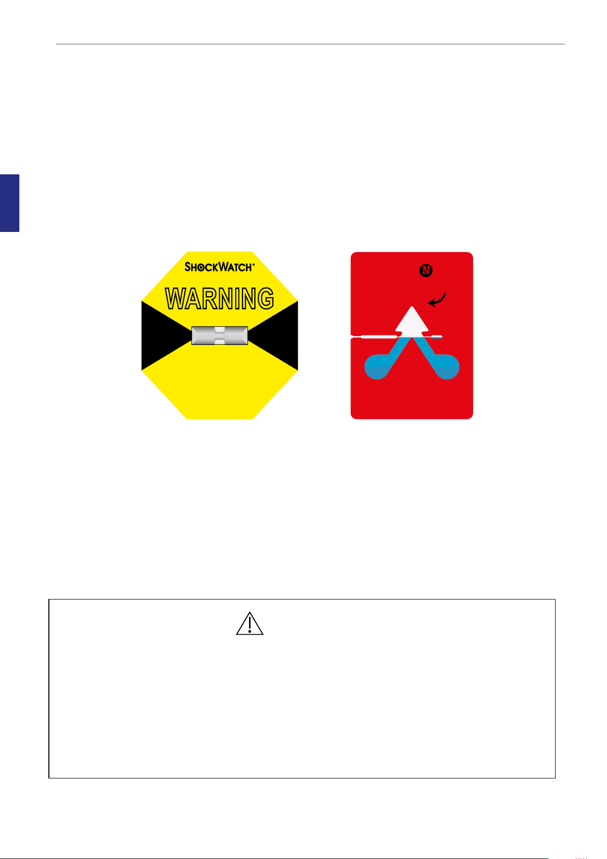
CAUTION
• DO NOT use the incubator if ShockWatch or TipNTell has been triggered or if the package is
damaged
• Read and understand the manual completely before use. Keep the manual close to the unit
• Never use or handle this unit in ways other than specified in this manual. Your safety may be at
risk and the unit may get damaged
• Never try to move the unit without consulting Technical Support
• Never use the unit if the alarm system of the device has issued a failure message and the cause
of the failure has not been identified
• Protect the power cord from being damaged or being restricted in any way. Unplug the power
cord from the wall socket or at the rear of the instrument to disconnect the mains supply
• Make sure that CO
• Always keep the red caps on unused gas inlets and the sample port at the back of the unit
• Never use the unit without an original K-Systems H13 filter
• DO NOT expose the filter to liquids. Change filters that have been exposed to liquids
• DO NOT leave lids open for more than 10 seconds
• DO NOT use the unit at ambient temperatures exceeding 30°C. Ambient temperature above
30°C will compromise the incubation process. The relative humidity must not exceed 75% (noncondensing)
and N2 gas supply pressures are not above 1.0 bar and not below 0.5 bar
2
2
7

2
Safety
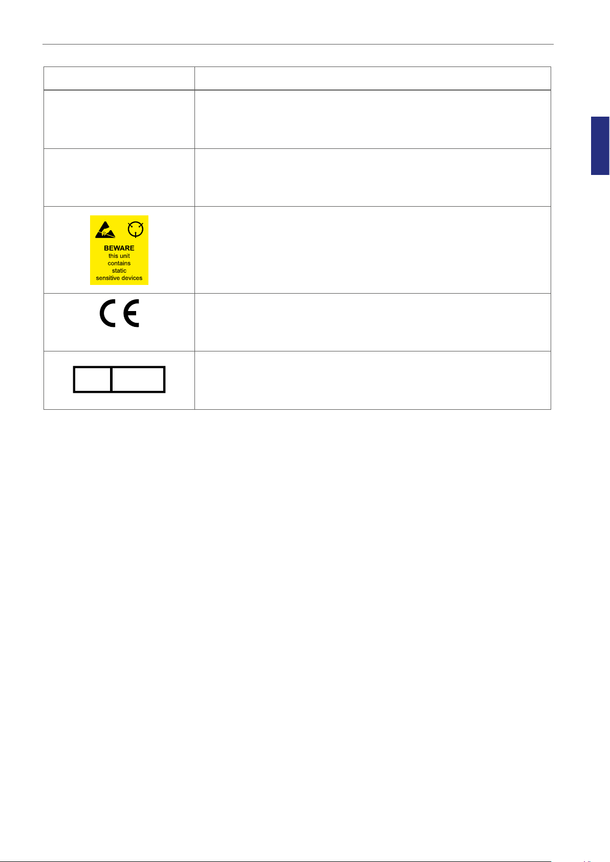
Symbol Meaning
WARNING: Indicates a potentially hazardous situation which, if not
avoided, could result in death or serious injury
CAUTION: Indicates a potentially hazardous situation which, if not
avoided, may result in minor or moderate injury. It may also be used
to alert against unsafe practices
Consult the User Manual for information needed for proper use of
the device
Manufacturer
S
N
REF
Date of manufacture
Waste electrical and electronic equipment
• CooperSurgical, and its distributors within the European Union
and associated states, have taken the necessary steps to comply
with the directive 2012/19/EU on waste electrical and electronic
equipment (WEEE)
• The instrument, when reaching its end of life, must be collected
and recycled separately from other waste according to national
requirements
Environmental implications: WEEE contains materials that are
potentially hazardous to the environment and to human health (see
page 52)
Serial Number
Catalog Number
Warranty label
8
Symbol Meaning
0086
Safety
Sample Port
GAS (MAX 1 BAR)
EC REP
Sample port
Gas Inlets CO2/N
Static sensitive (ESD)
In accordance with Annex II of the European Medical Device Directive
93/42/EEC, as amended by Directive 2007/47/EC
Authorized Representative in the European Community
2
2
9
3
HANDLE WITH CARE
WARNING
RED INDICATES ROUGH HANDLING.
IF RED, NOTE ON THE BILL OF LADING
AND INSPECT PRODUCT
PRODUCT OF MEDIA RE COVERY
MODEL:
L-65 (25g)
MADE IN THE USA
www.shockwatch.com 1.800.527.9497
TIP
Installation
Section 3 - Installation
Installation of the G185 should be carried out by a CooperSurgical Service Technician or other
authorized personnel. Incorrect installation could result in overall poor performance.
The G185 is designed as a stationary unit and, therefore, not to be moved once it has been installed.
If the incubator needs to be relocated, please contact technical support.
Before Installation
This incubator is transported in a crate and we recommend you inspect its delivery. If the ShockWatch
or TipNTell has been triggered, inform customer service.
Check the contents to ensure all parts listed on the packing list are present.
BLUE BEADS IN
ARROW INDICATES
CONTAINER WAS
TIPPED OR
MISHANDLED
TELL
MADE IN THE U.S.A
Placement
The G185 should be placed on a level, secure surface, away from heaters, coolers,
air-conditioning outlets, mists, splash and direct sunlight. Allow 10cm of clearance on all sides to allow
adequate ventilation.
Allow the G185 to acclimatize for two hours before installation.
To maintain a device setpoint between 35-40°C the preferred ambient temperature should be
between 20-30°C. DO NOT use the incubator at ambient temperatures exceeding 30°C as this may
compromise the incubation process.
This unit is designed for use at altitudes under 2,000 meters.
• Installation of the unit should only be performed by an authorized CooperSurgical Service
Technician
• Never block any of the ventilation holes on the unit
• Make sure that all devices emitting electromagnetic radiation are kept at a reasonable distance
from the unit in order to avoid any potential interferences
• Make sure the power circuits used are intended for medical equipment
• Make sure there is sufficient access to the device for ease of disconnection if required
10
CAUTION
Intended Use
Section 4 - Intended Use
To provide an environment with controlled temperature at or near body temperature and gas level
(CO2, O2 and N2), for the development of human gametes and embryos during in vitro fertilization
(IVF) treatment.
Applicable indications for use are subject to the regulations of the country into which the device is
sold and also the availability of the G185 for clinical use is dependent on the regulatory approval
status of the incubator within the country.
Applicable Part Numbers
Order Code Description
K22400-110
K22400-230
K22200-110
K22200-230
Standard Incubator
SensorTech Incubator
Significant Performance Characteristics
The incubator has been developed and optimized for gametes and embryos cultured with an overlay
of either paraffin or mineral oil. Each chamber is designed to contain dishes from one patient only.
Operation Principle
The fertilized egg (zygote) is cultured for up to 6-7 days in a growth medium in the incubator with
a controlled environment (temperature and CO2/O2). It is then implanted in the same or another
woman’s uterus, with the intention of establishing a successful pregnancy.
User Profile
A trained health professional, who has the appropriate assisted reproduction technologies
qualifications. Only qualified personnel trained in using the G185 should operate the incubator.
4
CAUTION: If the equipment is used in a manner not specified by this manual, the
safety of the user may be at risk and the equipment may be damaged. Always use the
equipment as stated in this User Manual
Operating Environment
To be used at ambient temperature in a medical environment, clinic or hospital laboratory under
normal working conditions.
11
Intended Use
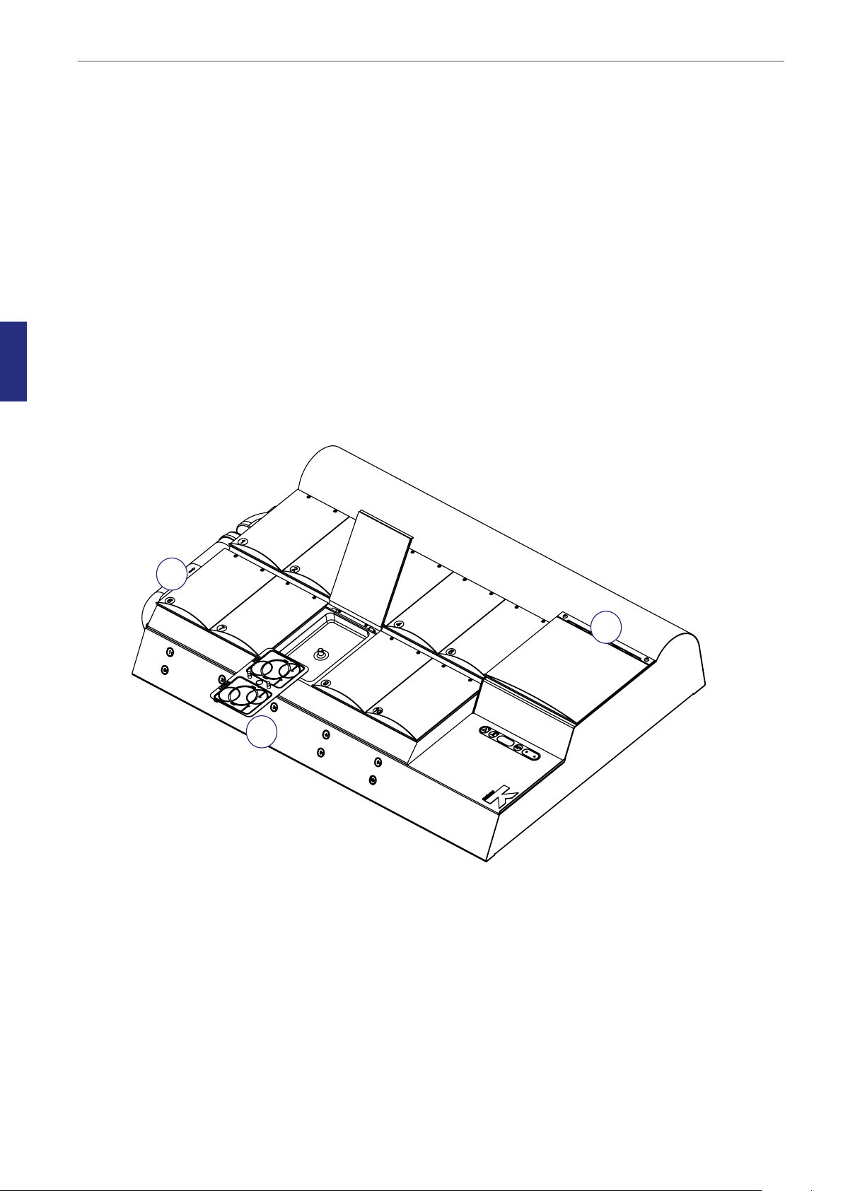
Product Description
The G185 is composed of 10 separate culture chambers (2) and one larger warming chamber (3).
The 10 culture chambers are exposed to both heat and gas mixtures while the Dry Bath Chamber is
exposed only to heat.
The gas is constantly cleaned for particles, volatile organic compounds and bacteria by circulation
through a HEPA and VOC filter and through a 254nm UV chamber.
4
The CO
sensor placed in the gas mixing chamber (built inside the incubator).
concentration is monitored by using a CO2 sensor and the O2 level is monitored by an O
2
2
Dish Inserts
The chambers should only be fitted with special Dish Inserts (1), that allow safe placement of standard
culture dishes (Falcon, Nunc, Vitrolife).
Ensure the culture dishes are placed securely in the correct milled grooves of the Dish Inserts.
2
3
1
12

Section 5 - Product Overview
Main Components
Components
1 Incubator Chambers
2 User Interface
3 Dry Bath Chamber
4 H13 Filter
5 Product label
Product Overview
6 Mains connection with fuse
7 Gas inlet connectors
8 Alarm output
1
5
G185 Standard and SensorTech models front view
3
2
G185 Standard model - back view
5
7
8
6
4
13
5
Product Overview
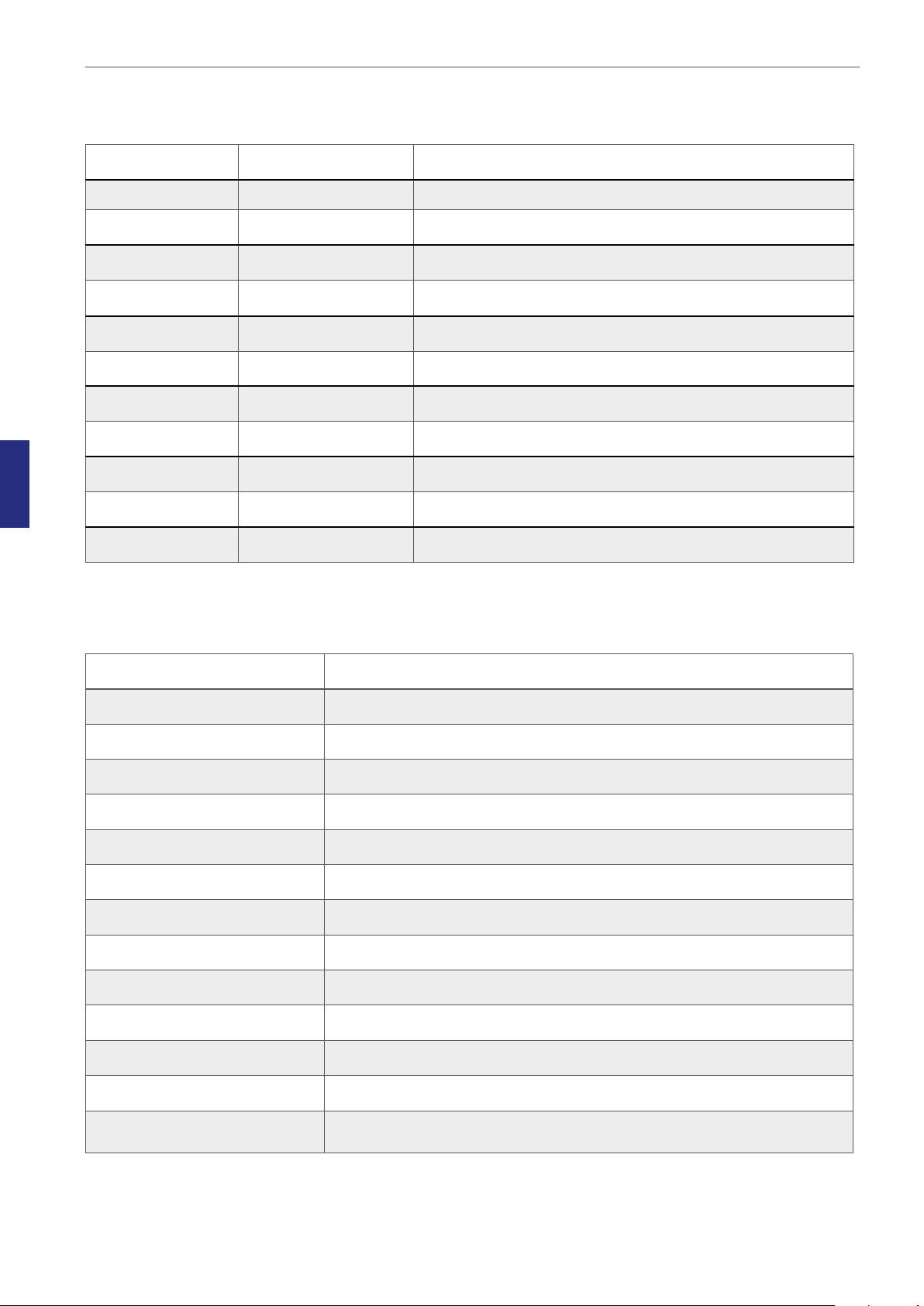
Supplied Accessories for G185 Incubator
Quantity Part Number Description
1 2-02-650 Mains Cable UK Plug 230V
1 2-02-651 Mains Cable Schuko Plug 230V
1 2-02-652 Mains Cable USA Plug 115V
1 2-02-662 Mains Cable Aus/China Plug 230V
2 K11066 Silicone Tube (3 metre)
4 K22123 Silicone Sealing Rings
2 K53830 HEPA VOC Filters
2 K22166 HEPA Filter for Input Gas Supply
10 K57263 Magnetic Pads for Incubator
1 K33098 USB (Datalogger Software)
1 K57314 USB Converter Cable
Accessory Order Codes
Order Code Description
23063-1 Dish Insert Falcon 1 pc
23064-1 Dish Insert Nunc 1 pc
23069 Dish Insert Vitrolife 1 pc
23060-1 Dish Insert Nunc pH Online Sensor (SensorTech models only)
23061-1 Dish Insert Falcon pH Online Sensor (SensorTech models only)
23079 Dish Insert Vitrolife pH Online Sensor (SensorTech models only)
22166 H13 Filter
53830 HEPA Inline Filter
57214 Lid Seal for culture chambers
14
57272 Lid Seal for Dry Bath Chamber
11103 G100 Gas Analyzer
11006 Solid Temperature Sensor (use with K-Systems F100 Thermometer)
33070 User Manual
Product Overview
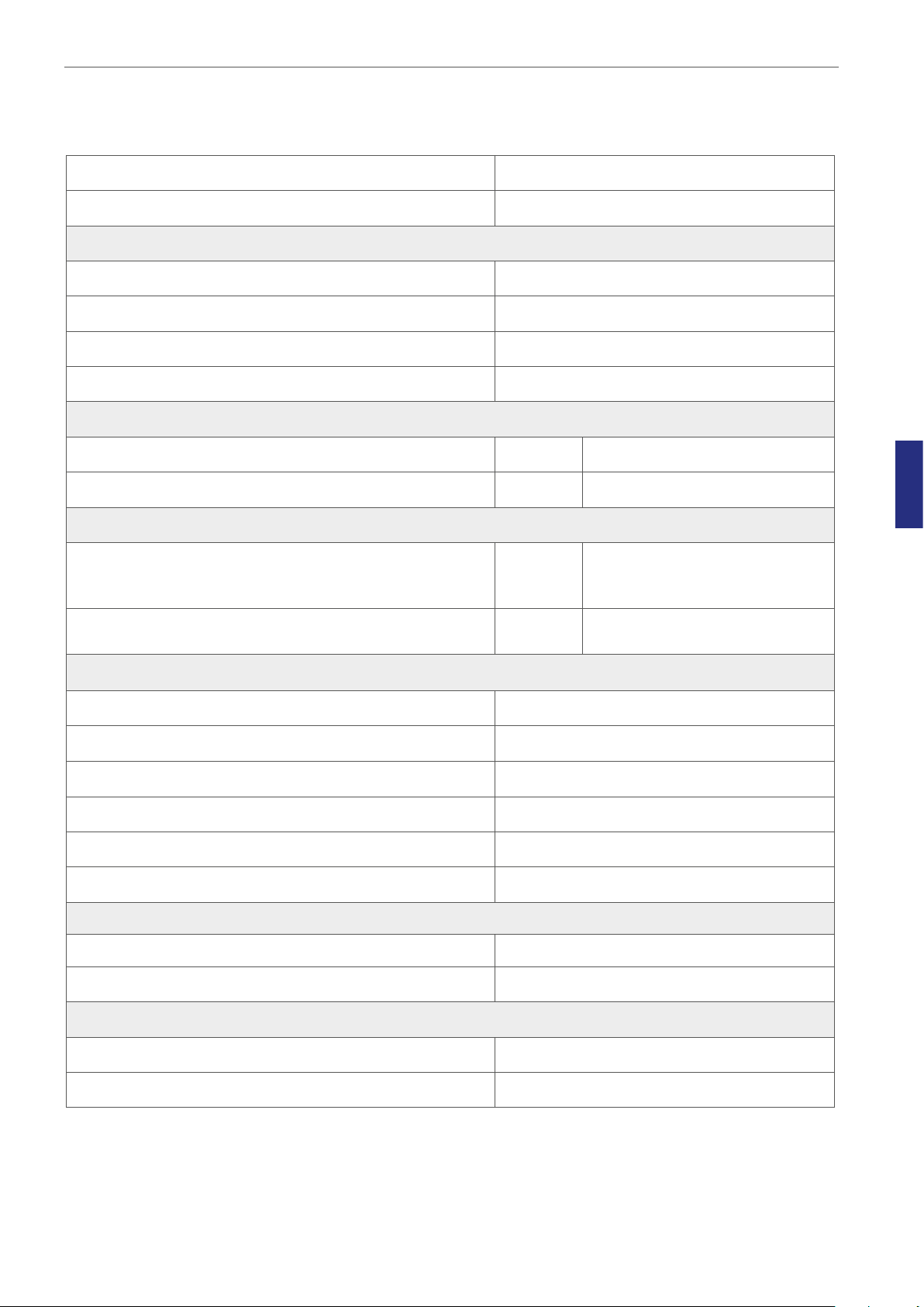
Technical Specifications
Overall dimensions, (L x W x H) 922 x 570 x 165mm (with filter connected)
Weight 38kg
Ambient conditions
Max. ambient temperature during operation 30°C
Min. ambient temperature during operation 20°C
Max. storage temperature 30°C
Min. storage temperature -10°C
Humidity
Max. humidity during operation % R.H. 75, non-condensing
Max. storage humidity % R.H. 95, non-condensing
Filters
high-efficiency, acid-washed,
VOC Filter H13 filter capsule 1 pc
granular-activated carbon
combined with HEPA
Gas inline filter, HEPA 2 pcs
50mm HEPA disc filter for the
protection of internal circuits
Gas and Temperature
Temperature Range From ambient T°- 42.9°C
range 2 - 10%
CO
2
O
range 2 - 20%
2
Temperature specification (zone) accuracy Better than +/- 0.3°C deviation
gas control accuracy Better than +/- 0.2% average
CO
2
gas control accuracy Better than +/- 0.2% average
O
2
Gas Consumption (typical)
5
CO
N
2
CO
O
2
1.5l/h
7l/h
Recovery time
2
2
2 min
4 min
15
Product Overview
Voltage
5
Rated Voltage (system)
Current
Power consumption max. 240 VA
Connecting gas
inlet 1.0 bar/14.5 psi
CO
2
inlet 1.0 bar/14.5 psi
N
2
Dish Inserts
Nunc dish insert
Falcon dish insert
Vitrolife dish insert Vitrolife 4 well dishes
Software
To monitor, record and display key performance Data logger, including alarm functions
1/N/PE AC, 100-120VAC 60Hz or 220240VAC 50Hz
Suitable for Nunc Ø35mm, Ø51mm and
4 well IVF dishes
Suitable for Falcon Ø50mm, 4 well IVF
dishes
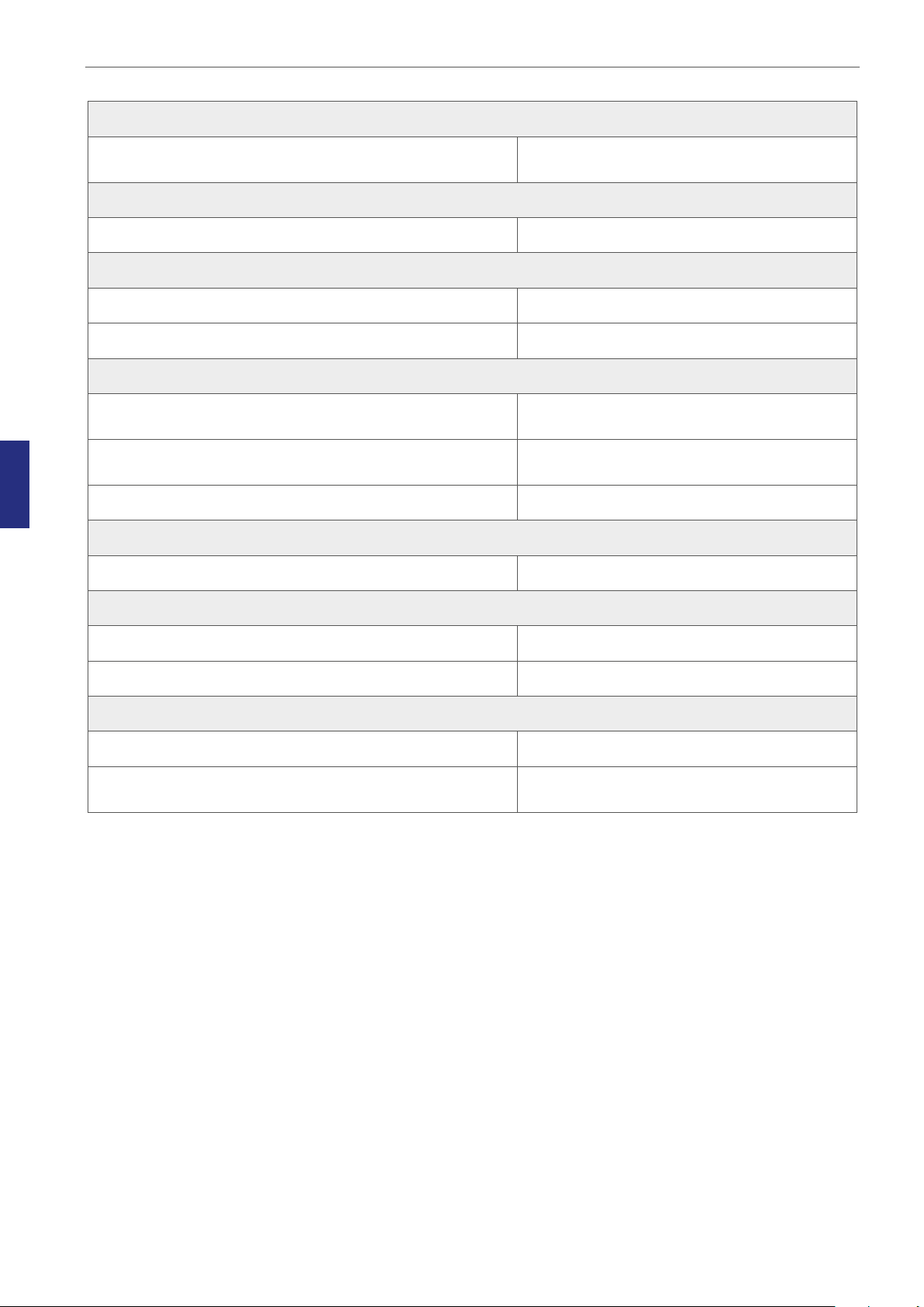
Fuses
External fuses (220-240V) 2 x F 1.6AH (250V)
External fuses (100-120V) 2 x F 3.15AH (250V)
Degree of protection
Type of protection against electric shock Class I
Degree of protection against the ingress
of water
IP30
16
G185 SensorTech
Section 6 - G185 SensorTech
G185 supports external and independent monitoring of the most critical parameters regarding CO2
concentration, temperature and pH measurement.
CAUTION: Installations of external sensors must be performed by CooperSurgical or
by persons authorized by CooperSurgical only
External pH Monitoring
This G185 SensorTech has been designed to work with Octax pH online. These parts are available
from MTG GmbH.
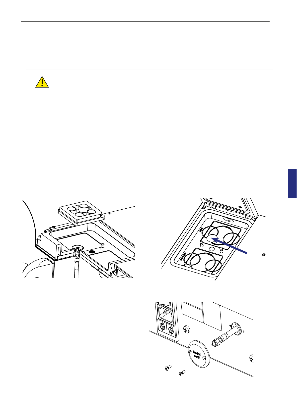
A fiber optic cable is built into chamber 1.
A special Dish Insert must be used in the chamber where the pH optical fiber sensor is installed. There
are three different Dish Inserts available depending on the dishes used:
• Dish Insert Nunc pH Online Sensor: Order code: 23060-1
• Dish Insert Falcon pH Online Sensor: Order code: 23061-1
• Dish Insert Vitrolife pH Online Sensor: Order code: 23079
Fiber Optic Cable in chamber 1
The fiber optic cable is attached to a cover plate
on the rear panel.
Special dish insert hole for Optical Fiber Sensor
6
When this cover plate is removed the fiber optic
cable will follow out. An O-ring in the rear panel
protects the cable from scratching against
metal.
A stopper is mounted on the cable inside to
prevent the cable from being pulled out too far,
thereby breaking the fiber.
Outlet of Fiber Optic Cable in rear panel
17
 Loading...