

Cooper Sound CS 208 V2 Operator's Manual

CS 208 V2 PROFESSIONAL AUDIO MIXER
OPERATOR’S MANUAL
645 Main Street, Suite C ■ Morro Bay, California ■ (805) 772-1007 ■ Fax (805) 772-1098
www.coopersound.com

CS 208 v2
Cooper Sound Systems, Inc.
TABLE OF CONTENTS
INPUT CHANNEL DESCRIPTION.............................................................................1, 2
OUTPUT MODULE DESCRIPTION ..........................................................................3, 4
REAR PANEL DESCRIPTION .......................................................................................5
PIN OUTPUTS ...............................................................................................................6
STEREO MODULE (OPTIONAL) ..............................................................................7, 8
SPECIFICATIONS
GENERAL ......................................................................................................................9
INPUTS ........................................................................................................................10
OUTPUTS.....................................................................................................................11
BLOCK DIAGRAM - INPUT & POWER WIRING.........................................................12
BLOCK DIAGRAM - OUTPUT .....................................................................................13
EQ CHARTS ................................................................................................................14
LAYOUT - A,B,C...........................................................................................................15
LAYOUT - D,E,F...........................................................................................................16
LAYOUT - G,G PPM, H, MB ........................................................................................17
CSST BLOCK DIAGRAM & LAYOUTS........................................................................18
BASIC SET UP & METERING...............................................................................19, 20
OPERATION & APPLICATION NOTES ...................................................21,22,23,24,25
APPLICATION NOTES
AN 1 v2 ROLLS............................................................................................................26
AN 2A INPUT CHANNEL OPTIONS............................................................................27
AN 2B v2 INPUT CHANNEL OPTIONS.......................................................................28
AN 2C v2 INPUT CHANNEL OPTIONS.......................................................................29
AN 2D v2 INPUT CHANNEL OPTIONS.......................................................................30
AN 2E v2 INPUT CHANNEL OPTIONS.......................................................................31
AN 3 v2 COMMUNICATIONS IN .................................................................................32
CABLE WIRING ...........................................................................................................33
GENERAL NOTES.......................................................................................................34
ADC OPTION - INSTRUCTIONS.................................................................................35
ADC OPTION - SPECIFICATIONS ..............................................................................36
WARRANTY.................................................................................................................37
MODEL CS 208 v2
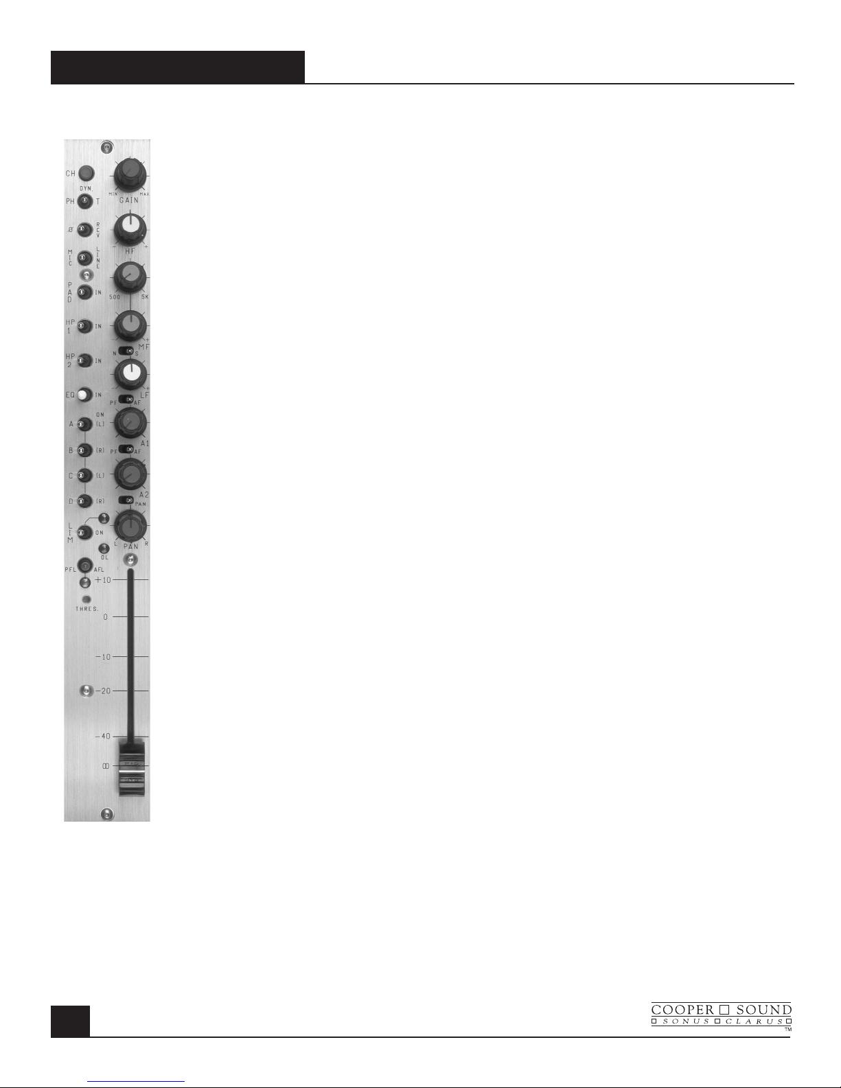
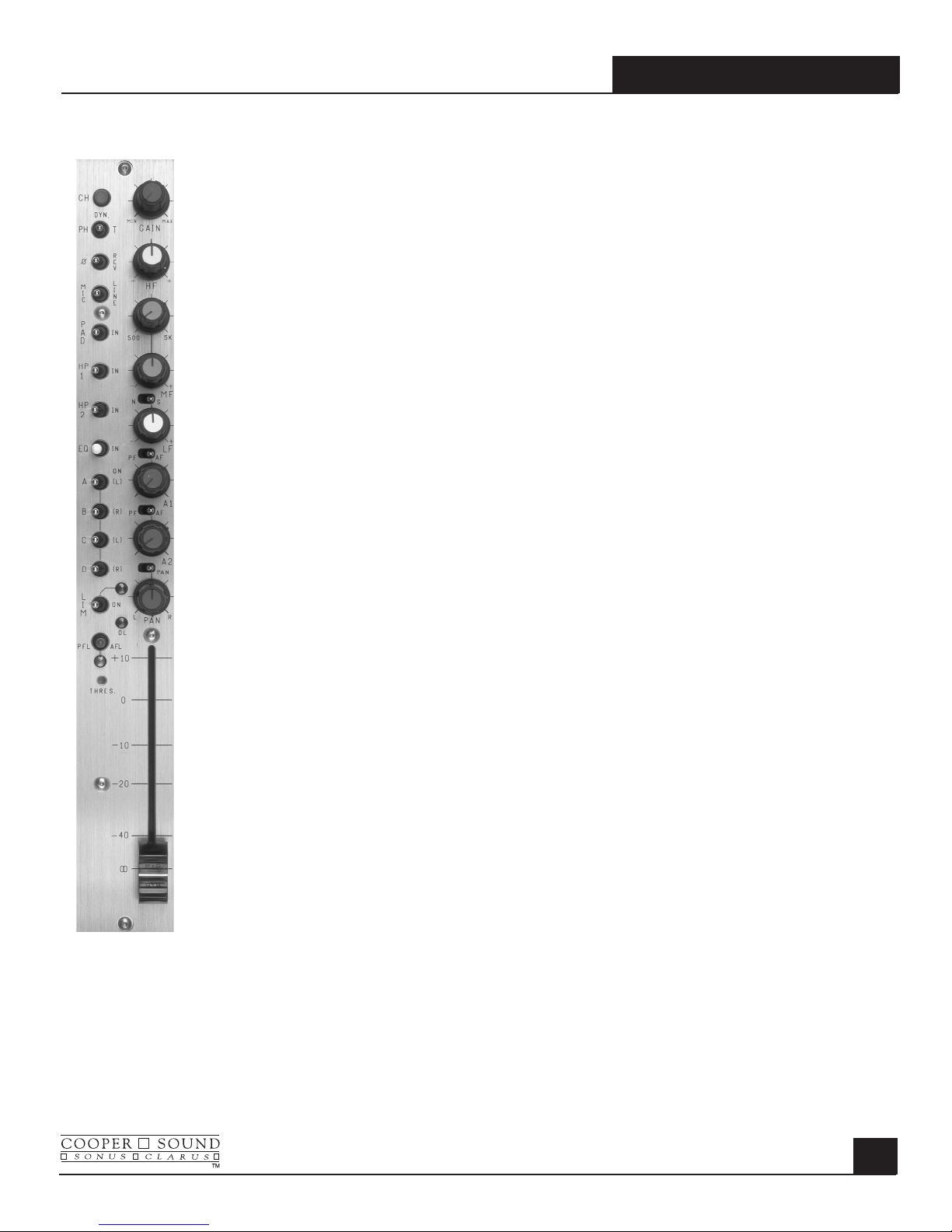
Left Section
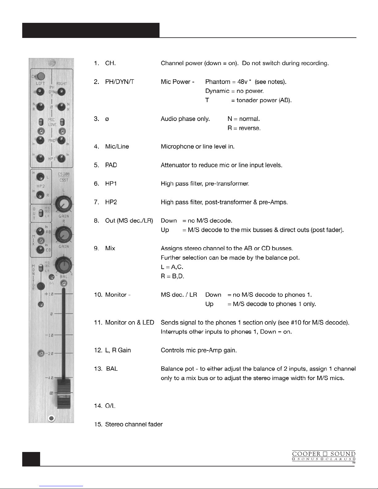
1. CH: Channel Power (down = on) Do not switch during recording.
2. PH/DYN/T: Phantom power, no mic power, T (AB) power
(Phantom power is normally 48 v, see layout A to change to 12 v).
3. ø: Phase (audio only). ø = normal phase, REV = reverse phase
4. Mic/Line: Microphone or line level in.
5. Pad: Attenuator to reduce either mic or line input levels.
6. HP 1: High pass filter, pre-transformer.
7. HP 2: High pass filter, post transformer & preAmps.
8. EQ: Equalizer bypass. Affects HF, MF & LF filters, not HP filters.
9-12. A,B,C,D: Channel to mix bus assigns. L(left), R(right) indicate monitor & pan
pot assignment.
13. LIM+LED: The limiter is a symmetrical peak detecting type & is completely out
of circuit when switched off. Threshold: See (15). Attack & release
times are preset internally (see layout A to change). The LED
indicates limiter action.
14. PFL/AFL+LED: Pre fade listen or After fade listen (post fader). The switch is not
momentary, the LED serves as warning that PFL or AFL is
selected.
15. Thres. Limiter threshold. Clockwise = lower threshold.
16.O/L Near overload indicator.
INPUT MODULE
MAY 2003
1
MODEL CS 208 v2
MAY 2003
INPUT MODULE
2
Right Section
17. Gain: Mic/Line preamp gain.
18. HF: High frequency amplitude control.
19. MF 500, 5k Mid-frequency select.
20. MF: Mid-frequency amplitude control.
21. N/S: N = normal, S = side for M/S decoding.
‘S’ inverts phase to B & D busses allowing one pair of channels to be
used with a M/S mic configuration and decoded to a L/R stereo signal
(this is an option, see separate application note).
22. LF: Low frequency amplitude control.
23. PF/AF: Selects pre or after fader for Aux 1 send.
24. A1: Aux 1 send (the aux sends are not affected by the ABCD mix bus
switches).
25. PF/AF: Selects pre or after fader for Aux 2 send.
26. A2: Aux 2 send.
27. Pan (switch): Switching the pan switch to the left disengages the panpot.
Crosstalk is therefore minimized and the output levels will remain equal.
28. Pan (pot): (L) = A & or C
(R) = B & or D
29. Channel fader
MODEL CS 208 v2
OUTPUT MODULE
MAY 2003
3
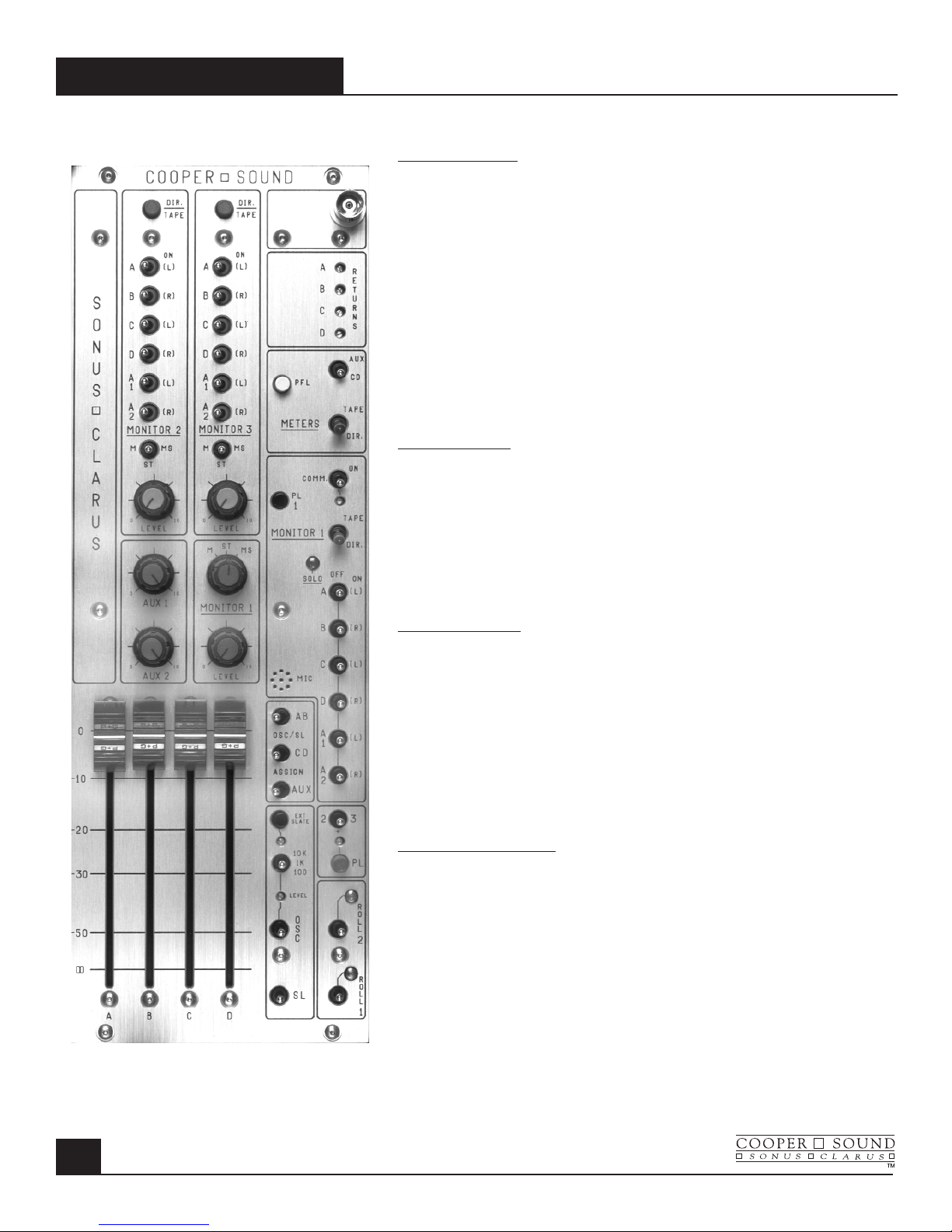
Monitor 2 & 3
1. DIR/TAPE: Selects direct or tape return signals (for
busses ABC & D).
2-7. A,B,C,D,A1,A2: Assigns busses to Monitor 2/3 outputs
(L) = left, (R) = right when using stereo
headphones.
8. M/ST/MS: M = mono, ST = stereo, MS = mid-side. Only
applicable if stereo headphones are used.
(See rear panel)
9. LEVEL: Gain Adjustment.
Aux 1,
Aux 2
10,11.: Aux 1 & 2 master level controls.
12. BNC: 12 volts available to power a ‘Littlite’®
(See meter panel).
13. RETURNS: Trim pots (multiturn) to adjust return (tape)
level to Monitors 1, 2 & 3 and the meters.
Meter Section
14. AUX/CD Meters 3, 4 = CD or Aux outputs
(3 = C or A1, 4 = D or A2).
15. PFL: Meters 1, 2 can indicate PFL selected on the
input channels (momentary switch).
16. TAPE/DIR: Tape/Direct. Meters indicate the return sig-
nals. (1 = A, 2 = B, 3 = C, 4 = D). CD/Aux
switch (14) overrides the tape return.
Monitor 1 Section
17. COMM: Communications return (talkback) to Monitor
1 only (See appl. note for 2 returns). The
multiturn trimmer below this switch adjusts
the level.
18. PL 1: Private line assign to Monitor 1 (down = on).
See master PL switch #28.
19. TAPE/DIR: Tape or Direct to Monitor 1
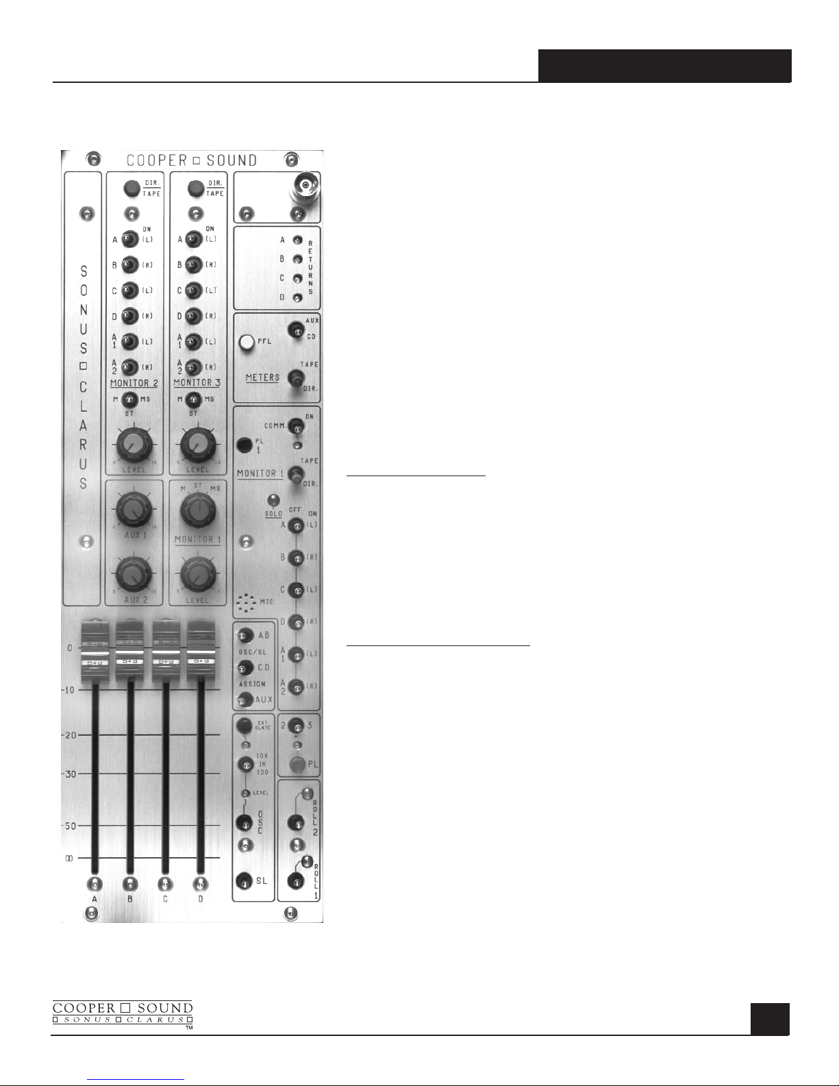
20. SOLO/OFF/ON
A,B,C,D,A1,A2:
Any combination of busses can be
monitored. ’SOLO’ disconnects the other-
busses to the Monitor 1 output - Solo
normally mono’s the signal to the
headphone out - there is an internal slide
switch to defeat this. ‘ON’ - In stereo mode
the busses are assigned to either (L) left or
(R) right.
21. M/ST/MS: M = mono, ST = stereo, MS = mid-side
(Monitor 1) Any combination selected by switch (20)
can be monitored in mono, stereo or
mid-side.
22. LEVEL: Gain control.
(Monitor 1)
23. MIC:
Internal slate mic (See #24, 25, 27).
OSC/SL SECTION
24. AB/CD/AUX: Assigns the oscillator or slate to AB,CD or
Aux busses- The aux. bus switch now has
3 positions. Left = off, Center = Aux 1 only,
Right = Aux 1 & 2.
25. EXT SLATE: Down = external slate mic input (on rear
panel). The trimmer below adjusts the slate
mic level.
OSCILLATOR SECTION
26. 10k/1k/100: Frequency select for the internal oscillator.
LEVEL: Adjusts oscillator level (multiturn).
OSC: Internal oscillator - Up = on,
Down = momentary on.
27. SL: Slate mic; Down = with LF (low frequency)
tone. Up = no LF tone.
28. PL SECTION: Master private line to Monitors 1, 2 or 3.
The level is adjusted by the multiturn
trimmer above.
2/+/3: Assigns PL to Monitor 2, 2 & 3 or Monitor 3
only.
29. ROLL 1,2: Independent remote control for many types
of recorders (see separate application
note).
30. MASTER FADERS: ABCD - Normally left at maximum for
optimum headroom and signal to noise
ratio.
MODEL CS 208 v2
MAY 2003
OUTPUT MODULE
4

LEFT TO RIGHT
MONI 2, MONI 3: Monitor 2 & 3 outputs - for stereo or mono headphones
(or mono wireless communications).
FUSE: 2.5 A (5 x 20 mm).
EXT POWER: Pin 1 = negative DC, Pin 3 = Battery charge (positive),
Pin 4 = Positive DC (see specifications).
AES OUTS (Option) Digital outputs for A,B,C,D busses.
Clock reference in (upper BNC). Clock reference out (lower BNC)
UNBALANCED OUTS(TQG): A,B,C,D Pin 1 = ground, Pin 2 = signal.
UNBALANCED OUTS(DB9): A,B,C,D.
BALANCED OUTS(XLR): A,B,C,D, Aux 1, Aux 2.
ROLL 1 & 2: Remote control for various recorders.
MIX BUS IN: A,B,C,D (current input).
COMM IN: Communications input to Monitor 1 (balanced).
SL IN: External slate mic input.
RETURNS: A,B,C,D, balanced inputs.
BAL PREFADE OUTS(Option): Pre or post fader channel outputs (+4dBU balanced)
for multitrack recording (standard wiring).
DIR OUTS: Channel direct outs, post fader (unbalanced).
INSERTS: Can be changed to direct out, prefade (unbalanced). See Board A layout.
XLR Inputs: Transformer balanced (mic or line level).
2 spare holes: Stereo input channel option.
MODEL CS 208 v2
REAR PANEL
MAY 2003
5

MODEL CS 208 v2
MAY 2003
PIN OUTS
6
All XLR’s are wired pin 2 high. XLR 3M
Pin 1 = Ground
Pin 2 = High
Insert Pin 3 = Low
1/4” stereo jack Tip = Send
Ring = Return
Phones 1, 2, 3
Sleeve = Ground 1/4” stereo jack (max load = 25Ω per channel)
or direct out, prefader Tip = Left
(see appl. note AN 2A & 2B v.2) Ring = Right
Sleeve = Ground
Direct Out Comm. In.
(post fader) XLR 3F
1/4” mono jack Tip = Signal Pin 2 = High
Sleeve = Ground Pin 3 = Low
Pin 1 = Ground
(See application note AN 3 v.2 for multiple inputs)
Mix Bus in
DB9 1 =Ground Returns
2 = D XLR 3F
3 = C Pin 2 = High
4 = A Pin 3 = Low
5 = B Pin 1 = Ground
(current input, see specifications)
Ext. Slate in
Outputs XLR 3F
DB9 1 = Ground Pin 2 = Signal
2 = A Pin 3 & 1 = Ground
3 = B
4 = C DB25 Balanced Outputs (Option)
5 = D Pin
Pin
Ch.1 Hot 24 Ch.5 Hot 18
TQG 3M Cold 12 Cold 6
Pin 1 = Ground Ground 25 Ground 19
Pin 2 = Signal
Pin 3 = N/C Ch.2 Hot 10 Ch.6 Hot 4
Cold 23 Cold 17
TQG 5M (roll) (See application note AN 1 v.2) Ground 11 Ground 5
Pin 1 = -10 v (Nagra)
Pin 2 = Stop (Nagra) Ch.3 Hot 21 Ch.7 Hot 15
Pin 3 = Pause/Stop (DATs) Cold 9 Cold 3
Pin 4 = Common (DATs) Ground 22 Ground 16
Pin 5 = Record (DATs)
Ch.4 Hot 7 Ch.8 Hot 1
Cold 20 Cold 14
Ground 8 Ground 2
MODEL CS 208 v2
CSST-STEREO MODULE
MAY 2003
7
Overload indicator.
MODEL CS 208 v2
MAY 2003
CSST-STEREO MODULE
8
-83 dBu (Z = 1.4kΩ)
+28 dBu
-40 dB Zin≈10kΩ
-15 dB Zin≈600Ω
-55 dB Zin≈10kΩ
EIN (20 - 20 kHz,150Ω)

MODEL CS 208 v2
SPECIFICATIONS
MAY 2003
9
General: (0 dBu ≈ .775v RMS)
Dimensions 16.5” x 15.2” x 5” (419 x 386 x 127 mm)
Weight with no batteries 19 lbs. (8.6 kg)
with alkaline cells 23lbs. (10.4 kg)
Overall distortion (THD + N) < 0.01% (0.003% typ.)
Equivalent input noise (150Ω 20-20kHz) -129.5 dBu
(150Ω ‘A’ WT’D) -131.2 dBu
Power Requirements:
External: 10v - 25v operating range.
Consumption with all channels on is ≈ 630 mA at 12v DC < 8 watts (410 mA at 18v DC)
Estimated battery life with 12v, 8 AH lead acid battery > 10 hours.
12v, 12 AH lead acid battery > 15 hours.
18v, 14 AH alkaline cells > 15 hours.
(Ni-CAD D cells are ≈ 1/3 the capacity of alkaline cells.)
XLR - 4M:
1 = Ground (-)
2 = N/C
*3 = Battery charge (+)
4 = External in (+) * Do not connect if rechargeable batteries are not installed.
Internal Power: 12 ‘D’ alkaline cells
PPM
VU Nordic
Battery test: + 18v DC = +2 +3 Full Scale (Last mark)
+ 12v DC = -6 0 +4
+ 10.5v DC= -8 -1 +2
BNC light: +12v out, 500 mA max. (1815 bulb ≈ 180 mA).
Power on LED: Turns off when the voltage is 11v or less.
Power cut off voltage: ≈ 10v DC (internal supply switches off).
48v Phantom: 48v +/- 1v.
12v T: 12v +/- 1v.

MODEL CS 208 v2
MAY 2003
SPECIFICATIONS
10
System Power Connections and Precautions:
RE: (+) chassis equipment.
The Nagra must have a separate supply, with no common power supply connections to the mixer or other (-)
chassis equipment.
Input:
Reference: -8PPM, 0VU (XLR’s are pin 2 high).
Mic In: (Transformer balanced)
Minimum input level -83 dBu (Z in 1.4k Ω)
Maximum input, line position (no pad) +28 dBu (Z in 10k Ω)
Pad 15 dB Z in ≈ 600Ω
Mic/Line 40 dB Z in ≈ 10kΩ
Combined 55 dB Z in ≈ 10kΩ
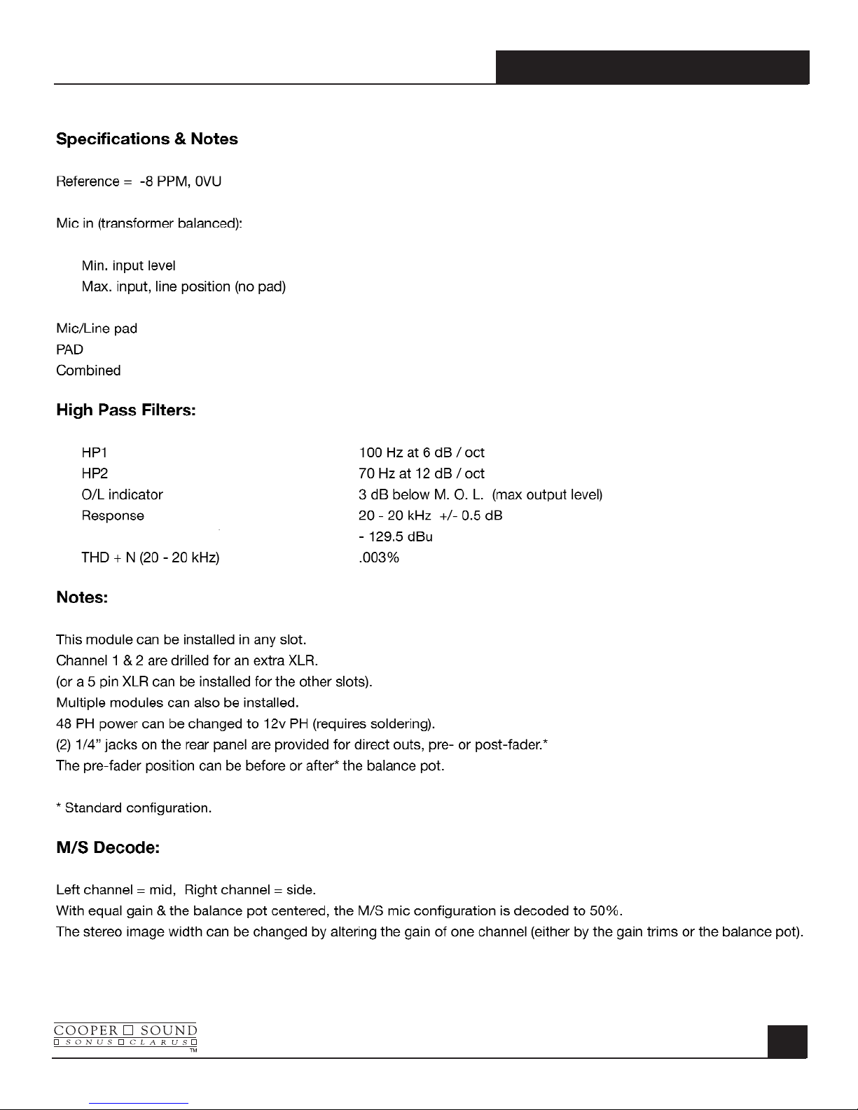
High Pass Filters:
Hp 1 Pre - transformer 100Hz -6 dB/oct.
Hp 2 Post - transformer & pre Amp. 70Hz -12 dB/oct.
EQ:
High frequency +/- 12 dB @ 10 kHz
Mid frequency +/- 15 dB 500 - 5 kHz
Low frequency +/- 12 dB @ 100 Hz
Insert: Send/direct out, pre-fader -11 dBu Z
out
= 47Ω (+4 dBu with boost)
Return -11 dBu Zin≈ 5kΩ
Direct out (post-fader): -8 dBu Z
out
= 47Ω
O/L indicator: -3 dB MOL
Limiter:
Threshold Variable* -6 PPM to M. O. L. (+4 PPM typ.)
Attack 1 ms
Release 150 ms
(M. O. L. = maximum output level = 25 dBu on XLR outs, +19 dBu on unbalanced outs.)
Pan pots: Center = -3 dB
All specifications are measured with the pan pots panned either L or R.
 Loading...