

Cooper Sound CS 208 Operator's Manual

CS 208 PROFESSIONAL AUDIO MIXER
1411 Marsh Street, Suite 105 ! San Luis Obispo, CA 93401 ! (805) 782-9750 ! Fax: (805) 782-9752
www.coopersound.com
OPERATOR’S MANUAL
645 Main Street, Suite C
Morro BayCAPhone: (805) 772-1007
Fax: (805) 772-1098
,
http://www.coopersound.com
93442-2273
USA

CS208
Cooper Sound Systems, Inc.
TABLE OF CONTENTS
INPUT CHANNEL DESCRIPTION ............................................................1, 2
OUTPUT MODULE DESCRIPTION ..........................................................3, 4
REAR PANEL DESCRIPTION ....................................................................... 5
PIN OUTS ..................................................................................................... 6
STEREO MODULE (OPTIONAL)............................................................... 7, 8
SPECIFICATIONS
GENERAL. ............................................................................................. 9
INPUTS ................................................................................................. 10
OUTPUTS ............................................................................................. 11
BLOCK DIAGRAM - INPUT & POWER WIRING .......................................... 12
BLOCK DIAGRAM - OUTPUT ...................................................................... 13
EQ CHARTS ................................................................................................14
LAYOUT - A, B, C ......................................................................................... 15
LAYOUT - D, E, MB ......................................................................................16
LAYOUT - F, G, G PPM, H ........................................................................... 17
CSST BLOCK DIAGRAM & LAYOUTS ........................................................ 18
BASIC SET UP & METERING................................................................. 19, 20
OPERATION & APPLICATION NOTES ................................. 21, 22, 23, 24, 25
APPLICATION NOTES
AN 1 ROLLS ................................................................................................ 26
AN 2A INPUT CHANNEL OPTIONS ............................................................ 27
AN 2B INPUT CHANNEL OPTIONS ............................................................ 28
AN 2C INPUT CHANNEL OPTIONS ............................................................ 29
AN 2D INPUT CHANNEL OPTIONS ............................................................ 30
AN 2E INPUT CHANNEL OPTIONS ............................................................ 31
AN 3 COMMUNICATIONS IN ......................................................................32
GENERAL NOTES ........................................................................................ 33
WARRANTY.................................................................................................. 34
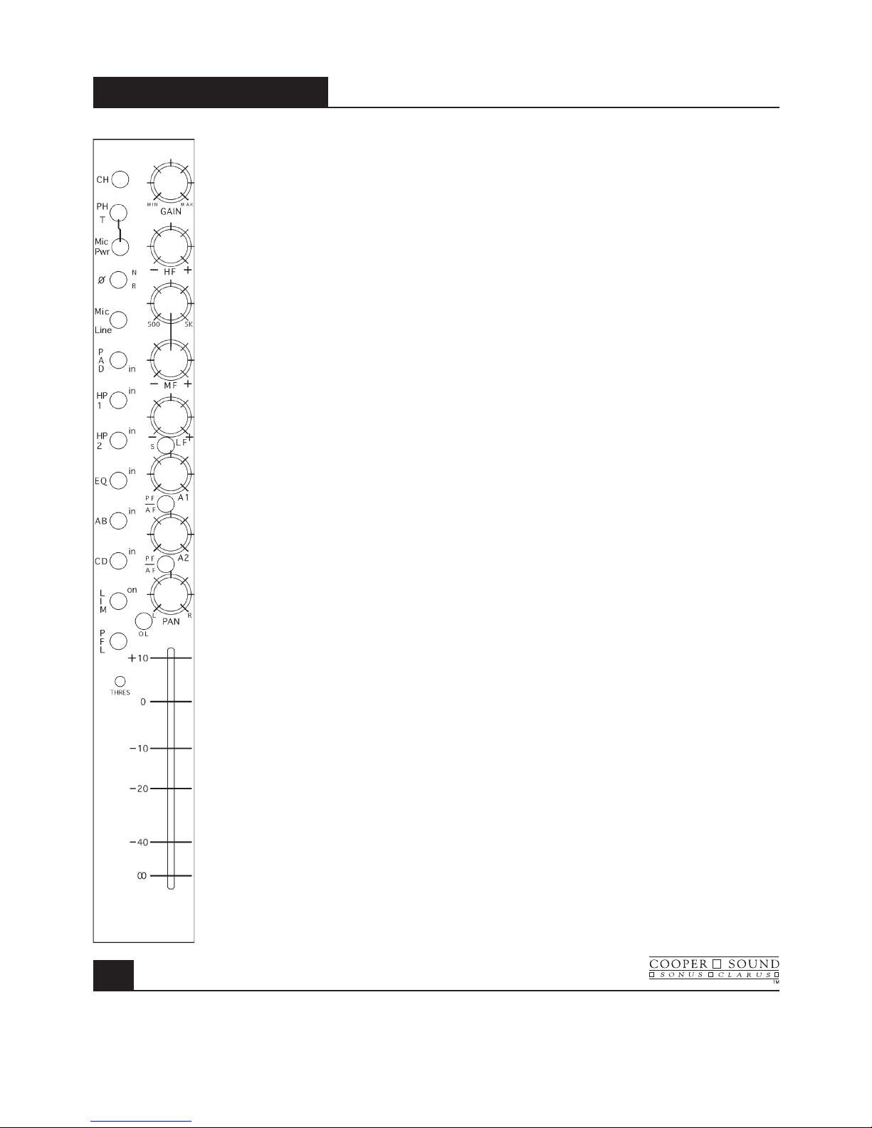
Left Section
1. CH : Channel Power (down = on) Do not switch during recording.
2. PH / T : Phantom Power, ‘T’ power (AB). (phantom power is normally 48v, see layout A
to change to 12v).
3. Mic Pwr : Turns on mic power (down = on).
Mic power type selected by the switch above.
4. ø : N = normal, R = reverse. Audio phase only.
5. Mic / Line : Microphone or line level in.
6. Pad : Attenuator to reduce either mic or line input levels.
7. HP1 : High pass filter, pre-transformer.
8. HP2 : High pass filter, post transformer & preAmps.
9. EQ : Equalizer bypass. Affects HF, MF & LF filters, not HP filters.
10. AB : Assigns channel to AB mix busses.
Further selection is made by the pan pot. A = L, B = R.
11. CD : Assigns channel to CD mix busses.
Further selection is made by the pan pot. C = L, D = R.
12. Lim : The limiter is a symmetrical peak detecting type & is completely out of circut
when switched off. Threshold: See (14). Attack & release times are preset
internally (see layout A to change).
13. PFL : Pre-fade listen.
Sends selected channel to phones 1 only.
(Cuts out all other inputs to phones).
Can be changed to AFL (see layout A).
14. Thres : Limiter threshold. Clockwise = lower threshold.
15. O / L : Near overload or limiter threshold indicator (see layout A).
INPUT MODULE
MODEL CS 208
1
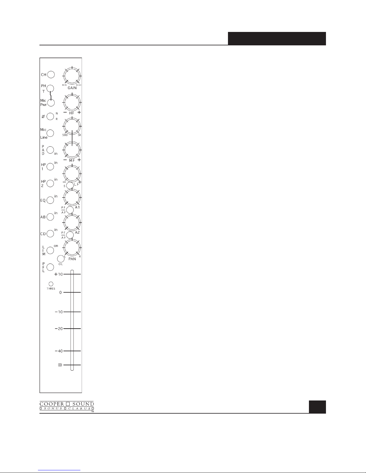
INPUT MODULE
MODEL CS 208
2
Right Section
16. Gain : Mic / Line preAmp gain.
17. HF : High frequency amplitude control.
18. MF 500, 5k : Mid-frequency select.
19. MF : Mid-frequency amplitude control.
20. LF : Low frequency amplitude control.
21. S : Invert phase option to B & D busses. 1 pair of channels could be used
to decode a M / S microphone configuration.
22. A1 : Aux 1 send (the aux sends are not affected by the AB,
CD mix bus switches).
23. PF / AF : Selects pre or after fader for Aux 1 send.
24. A2 : Aux 2 send.
25. PF / AF : Selects pre or after fader for Aux 2 send.
26. Pan : L = A and/or C, R = B and/or D.
Example: A out only. AB switch in, CD switch out,
Pan L (left).
27. Channel fader.
See specifications & application notes for further details.
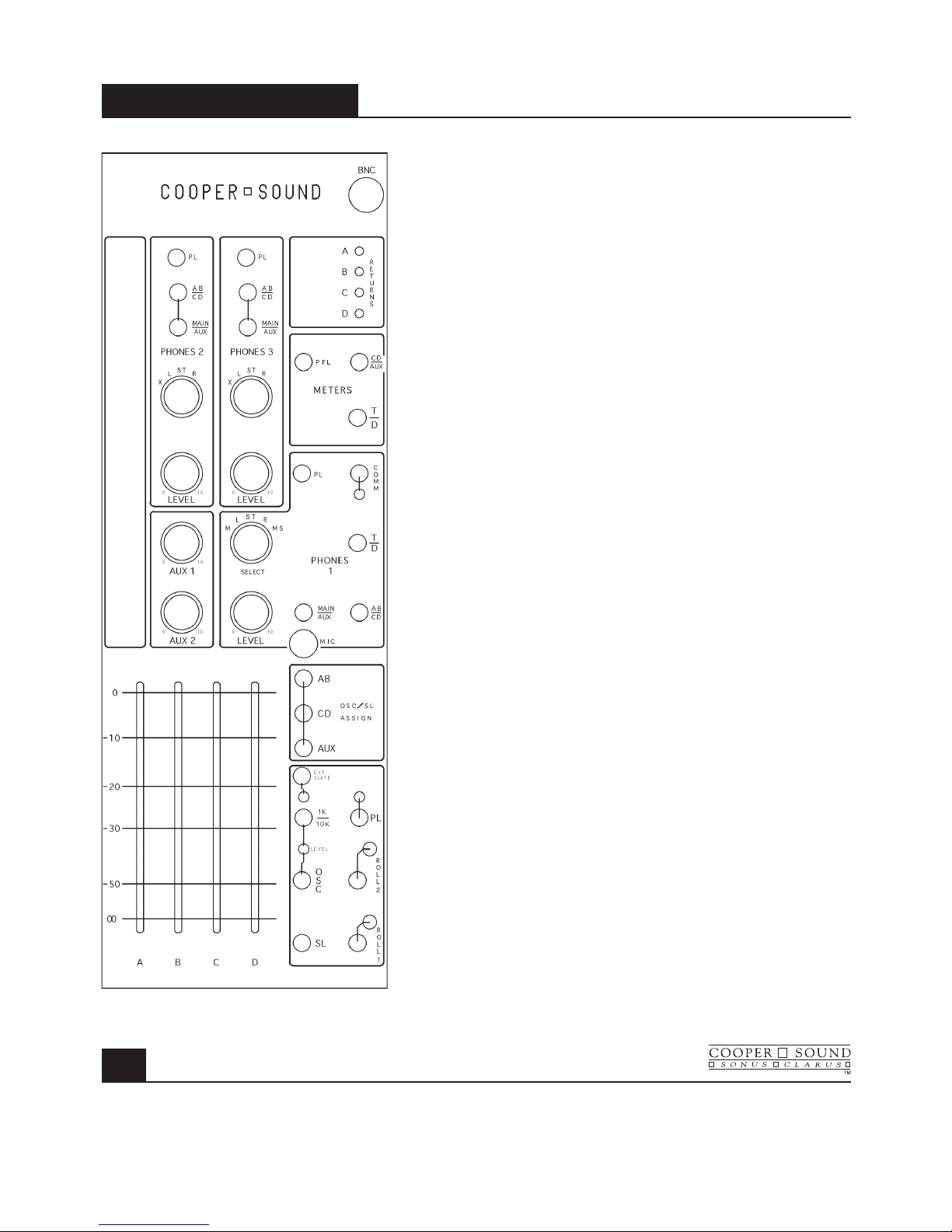
OUTPUT MODULE
MODEL CS 208
3
Phones 2 & 3
1. PL : Private line assign to phones 2 or 3
(down = on). See master PL switch (27).
2. Main/Aux : Selects main (ABCD) or Aux 1 & 2 to
phones 2 or 3.
(Aux 1 = L out, Aux 2 = R out.)
3. AB / CD : When main is selected, this switch selects
either AB or CD to L, R of the phone outs.
4. Rotary Select Switch :
X = phones 2 or 3 follows the phones 1 selection.
Example: Playback to phones 2 & 3 for director/
script critique. (Switch phones 1 to tape).
L = A, C or A1 to both outputs. (ie: Mono to L & R
headphone capsules). See (2 & 3).
ST = A, C, A1 to left capsule B, D, A2 to right
capsule. See (2 & 3).
R = B, D, A2 to both outputs. See (2 & 3).
5. Phones 2/3 level :
Gain adjustment.
Aux 1, Aux 2
6. Aux 1, 2 master level controls.
Returns
7. Trim pots (multi-turn) to adjust return (tape) level to
phones 1 & meters.
Meter Section
8. CD/Aux : Meters 3, 4 = CD or Aux outputs
(3 = C or A1, 4 = D or A2).
9. PFL : Meters 1, 2 can indicate PFL selected on the input
channels. (Momentary switch).
10. T/D : Tape/Direct. Meters indicate the return signals.
(1 = A, 2 = B, 3 = C, 4 = D). CD/Aux switch (8)
overides the tape return.
Phones 1
11. PL : Private line assign to phones 1 (down = on) see master
PL switch (27).
12. Comm : Communications return to phones 1 only. (down = on).
(Talkback to phones 1) (see app. notes for 2 returns).
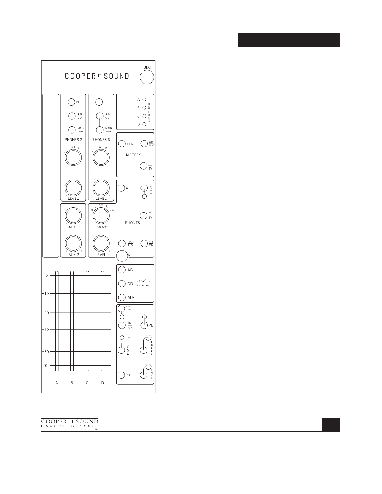
13. Comm. Trimmer : Adjusts return level.
14. T / D : Tape or direct to phones 1.
See AB / CD below (16).
15. Main / Aux : Selects either main, ABCD or Aux (A1, A2)
to phones 1.
16. AB / CD : When main is selected, group AB or CD
is sub-selected to phones 1. This also controls
the tape return (A = L, B = R, C = L, D = R).
17. Phones 1 selector :
M = Mono to both outputs.
L = A, C or A1 mono to both outputs.
ST = A, C, A1 = L. B, D, A2 = R.
R = B, D, A2 mono to both outputs.
M.S. = M/S decode to phones 1.
18. Level : Phones 1 gain control.
Mic
19. Internal slate microphone (See Ext. Slate) (21).
OSC/SL Assign
20. Assigns oscillator & slate to AB, CD or Aux outputs.
OSC, SL, PL, Roll
21. Ext. Slate : Selects internal or external slate mic.
Down = external slate input on rear panel.
(Bypasses internal slate mic).
22. Slate Trimmer : Controls level of both Int. & Ext. slate
(multi-turn pot).
23. 1k / 10k : Frequency select for internal oscillator.
Up = 1kHz, down = 10k.
24. Trimmer : Oscillator level (multi-turn pot).
25. Osc : Internal oscillator.
(up = on, down = momentary on).
26. SL : Slate mic.
down = with LF tone, up = no LF tone.
27. PL : Master private line & level control.
Directs slate mic to phones 1, 2, 3 only.
Assigned by (1 & 11).
28. Roll 1 & 2 : Up = on, down = pause or stop.
See “pin outs” for further details.
OUTPUT MODULE
MODEL CS 208
4
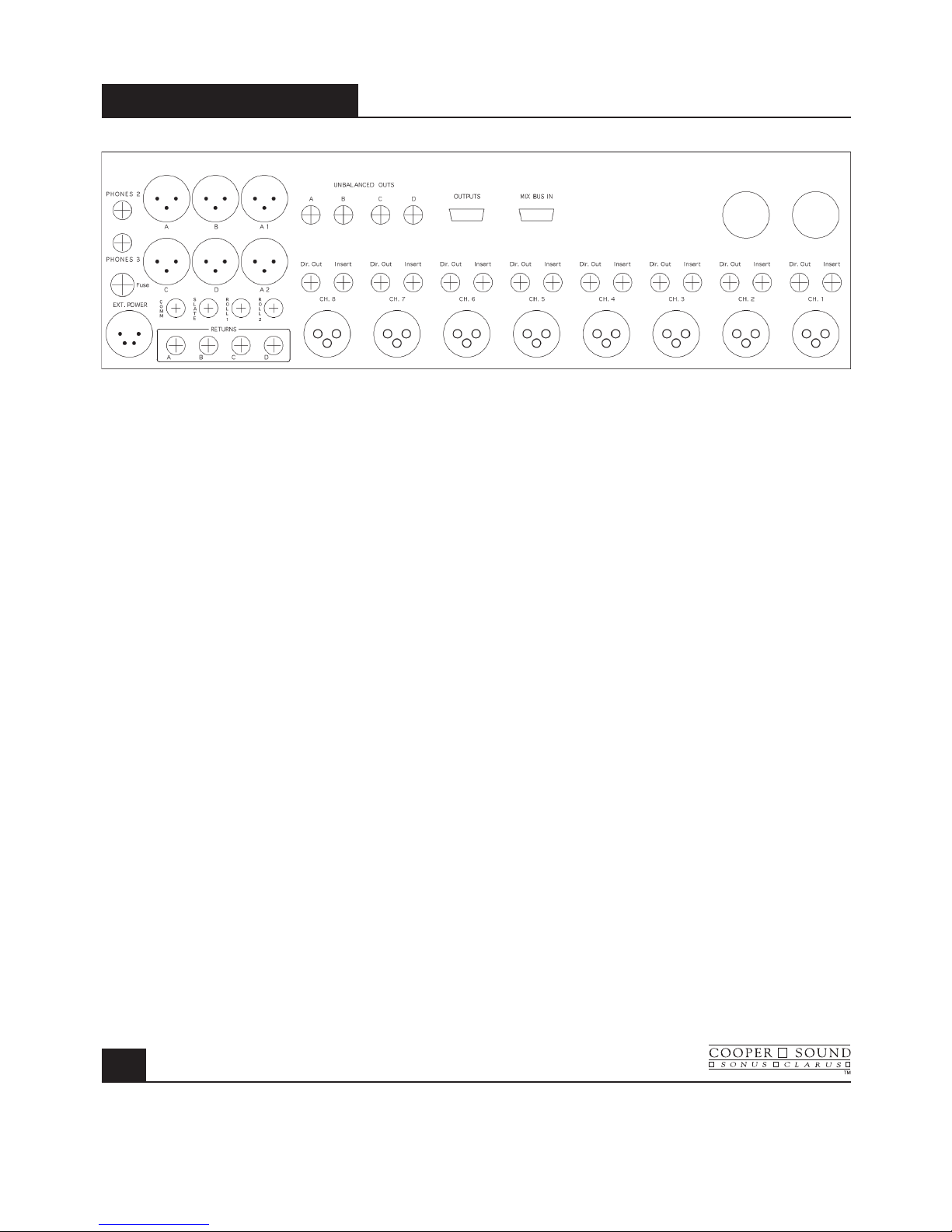
REAR PANEL
MODEL CS 208
5
1. Phones 2 : Stereo 1/4” jack.
2. Phones 3 : Stereo 1/4” jack.
3. Fuse : 2.5A (5 x 20mm).
4. Ext. Power In : Pin 1 = negative DC, Pin 3 = Battery charge (positive), Pin 4 = Positive DC
(see specifications).
5. A, B, C, D, A1, A2 : Balanced XLR outputs (Pin 2 high)
6. Unbalanced Outs (TQG) : ABCD Pin 1 = ground, Pin 2 = signal.
7. Unbalanced Outs (DB9) : ABCD.
8. Mix Bus In : ABCD (current input).
9. Comm. In : Talkback to phones 1. Balanced input. Stereo 1/4” jack.
10. Slate : External slate mic input. Mono 1/4” jack.
11. Roll 1, 2 : See pin outs.
12. Returns : ABCD Balanced in. Stereo 1/4” jack.
13. Ch. Dir. Out : Channel direct out, post fader. Mono 1/4” jack.
14. Ch. Insert : Can be direct out, pre-fader (see board A layout). Unbalanced stereo 1/4” jack.
15. 2 spare holes : Option for stereo input channels.

PIN OUTS
MODEL CS 208
6
All XLR’s are wired pin 2 high and are
transformer balanced.
Insert
1/4” stereo jack Tip = Send
Ring = Return
Sleeve = Ground
or direct out, pre-fader
(see app. note AN 2A & 2B)
Direct Out
(post-fader)
1/4” mono jack Tip = Signal
Sleeve = Ground
Mix Bus In
DB9 1 = Ground
2 = D
3 = C
4 = A
5 = B
(current input, see specifications)
Outputs
DB9 1 = Ground
2 = A
3 = B
4 = C
5 = D
TQG 3M
Pin 1 = Ground
Pin 2 = Signal
Pin 3 = N/C
TQG 5M
(roll) (See application note AN 1)
Pin1 = -10 v (Nagra)
Pin 2 = Stop (Nagra)
Pin 3 = Pause/Stop (DATs)
Pin 4 = Common (DATs)
Pin 5 = Record (DATs)
XLR 3M
Pin 1 = Ground
Pin 2 = High
Pin 3 = Low
Phones 1, 2, 3
1/4” stereo jack (max load = 25! per channel)
Tip = Left
Ring = Right
Sleeve = Ground
Comm. In
1/4” stereo jack
Tip = High
Ring = Low
Sleeve = Ground
(See application note AN 3 for multiple inputs)
Returns
1/4” stereo jack
Tip = High
Ring = Low
Sleeve = Ground
Ext. Slate In
1/4” mono/stereo jack
Tip = Signal
Ring & Sleeve = Ground

CSST-STERE0 MODULE
MODEL CS 208
7
1. CH. Channel power (down = on). Do not switch during recording.
2. PH/DYN/T Mic Power - Phantom = 48v * (see notes).
Dynamic = no power.
T = tonader power (AB).
3. ø Audio phase only. N = normal.
R = reverse.
4. Mic/Line Microphone or line level in.
5. PAD Attenuator to reduce mic or line input levels.
6. HP1 High pass filter, pre-transformer.
7. HP2 High pass filter, post-transformer & pre-Amps.
8. Out (MS dec./LR) Down = no M/S decode.
Up = M/S decode to the mix busses & direct outs (post fader).
9. Mix Assigns stereo channel to the AB or CD busses.
Further selection can be made by the balance pot.
L = A,C.
R = B,D.
10. Monitor - MS dec. / LR Down = no M/S decode to phones 1.
Up = M/S decode to phones 1 only.
11. Monitor on & LED Sends signal to the phones 1 section only (see #10 for M/S decode).
Interrupts other inputs to phones 1, Down = on.
12. L, R Gain Controls mic pre-Amp gain.
13. BAL Balance pot - to either adjust the balance of 2 inputs, assign 1 channel
only to a mix bus or to adjust the stereo image width for M/S mics.
14. O/L Overload indicator.
15. Stereo channel fader

Specifications & Notes
Reference = -8 PPM, 0VU
Mic in (transformer balanced):
Min. input level -83 dBu (Z in = 1.4 k!)
Max. input, line position (no pad) +28 dBu
Mic/Line pad -40 dB Z
in "
10k!
PAD -15 dB Z
in "
600!
Combined -55 dB Z
in "
10k!
High Pass Filters:
HP1 100 Hz at 6 dB / oct
HP2 70 Hz at 12 dB / oct
O/L indicator 3 dB below M. O. L. (max output level)
Response 20 - 20 kHz +/- 0.5 dB
EIN (20 - 20 kHz, 150!) - 129.5 dBu
THD + N (20 - 20 kHz) .003%
Notes:
This module can be installed in any slot.
Channel 1 & 2 are drilled for an extra XLR.
(or a 5 pin XLR can be installed for the other slots).
Multiple modules can also be installed.
48 PH power can be changed to 12v PH (requires soldering).
(2) 1/4” jacks on the rear panel are provided for direct outs, pre- or post-fader.*
The pre-fader position can be before or after* the balance pot.
* Standard configuration.
M/S Decode:
Left channel = mid, Right channel = side.
With equal gain & the balance pot centered, the M/S mic configuration is decoded to 50%.
The stereo image width can be changed by altering the gain of one channel (either by the gain trims or the balance pot).
CSST-STERE0 MODULE
MODEL CS 208
8

SPECIFICATIONS
MODEL CS 208
9
General: (0 dBu ! .775v RMS)
Dimensions 16.5” x 15” x 5” (419 x 381 x 127 mm)
Weight with no batteries 19 lbs. (8.6 kg)
with alkaline cells 23lbs. (10.4 kg)
Overall distortion (THD + N) < 0.01% (0.003% typ.)
Equivalent input noise (150" 20-20kHz) -129.5 dBu
(150" ‘A’ WT’D) -131.2 dBu
Power Requirements:
External: 10v - 25v operating range.
Consumption with all channels on is ! 630 mA at 12v DC < 8 watts (410 mA at 18v DC).
Estimated battery life with 12v, 8 AH lead acid battery > 10 hours.
12v, 12 AH lead acid battery > 15 hours.
18v, 14 AH alkaline cells > 15 hours.
(Ni-CAD D cells are ! 1/3 the capacity of alkaline cells.)
XLR - 4M:
1 = Ground (-)
2 = N/C
*3 = Battery charge (+) * Do not connect if rechargeable batteries are not installed.
4 = External in (+)
Internal Power: 12 ‘D’ alkaline cells
PPM VU
Battery test: + 18v DC = +2 +3
+ 12v DC = -6 0
+ 10.5v DC= -8 -1
BNC light: +12v out, 500 mA max. (1815 bulb ! 180 mA).
Power on LED: Turns off when the voltage is 11v or less.
Power cut off voltage: ! 10v DC (internal supply switches off).
48v Phantom: 48v +/- 1v.
12v T: 12v +/- 1v.
 Loading...