

Cooper Sound CS 106+1, CS 108+1 Operator's Manual
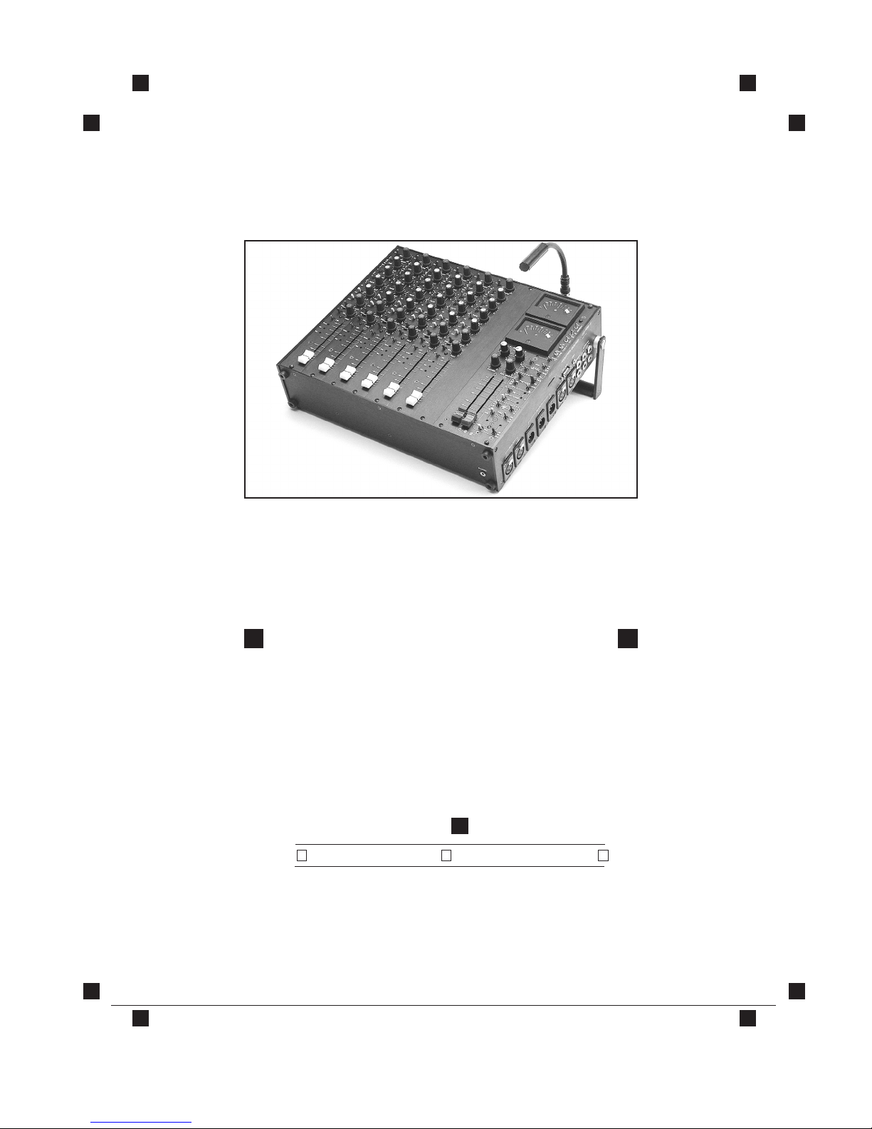
CS 106+1
CS 108+1
COOPER SOUND SYSTEMS, INC. ■ 1067 MAIN STREET ■ CAMBRIA, CA 93428 ■ (805) 927-8521
OPERATOR’S MANUAL
C O O P E R S O U N D
S O N U S C L A R U S
™


COOPER SOUND SYSTEMS, INC. ■ 1067 MAIN STREET ■ CAMBRIA, CA 93428 ■ (805) 927-8521
TABLE OF CONTENTS MODELS: CS 106+1
CS 108+1
INPUT CHANNEL DESCRIPTION .....................................................1-2
OUTPUT MODULE DESCRIPTION....................................................3-4
STEREO MODULE (OPTIONAL).......................................................5-6
AUX MODULE.....................................................................................7
SIDE PANEL DESCRIPTION .................................................................8
REAR PANEL DESCRIPTION (WITH CONNECTOR WIRING).............9
SPECIFICATIONS
GENERAL..............................................................................10
INPUTS ..................................................................................11
OUTPUTS...............................................................................12
EQ CHARTS ......................................................................................13
BLOCK DIAGRAM............................................................................14
TRIMMER AND SWITCH LOCATION DIAGRAMS.......................15-16
WIRING DIAGRAM ..........................................................................17
OPERATION & APPLICATION NOTES.........................................18-24
NAGRA IVS & 4.2 NOTES ................................................................25
METERING.........................................................................................26
GENERAL NOTES..............................................................................27
WARRANTY.......................................................................................28
PAGE 1 ■ JANUARY 1998 ■ REV. 3
INPUT PANEL MODELS: CS 106+1
CS 108+1
COOPER SOUND SYSTEMS, INC. ■ 1067 MAIN STREET ■ CAMBRIA, CA 93428 ■ (805) 927-8521
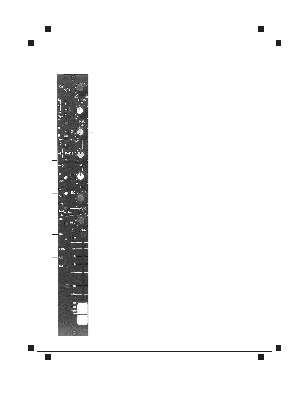
1. CHANNEL POWER: Do not switch during recording.
2. 12V / 48V
PHANTOM POWER.
3. MIC POWER SELECT:
Phantom (select voltage above)
Dynamic (no power)
"T" power (A B)
4. PHASE: Audio phase only
5. HIGH PASS FILTER 1: Pre-transformer.
6./7 PAD: ’-20’ SWITCH ‘-40’ SWITCH
up up =’O'
down up = 20
down down = 40
up down ='O'
8. HIGH PASS FILTER 2: Post mic preamp:
9. EQUALIZER SECTION
BYPASS:
Includes HF, MF & LF filters, but not
high pass filters
10. PRE / POST: Auxiliary send select
11. MIX BUS: Disables channel to mix bus to
enable channel to be used
discretely from the mixer outputs.
12. PFL: Sends selected channel to
"phones" only, cuts out all other
inputs to "phones" when
operated.
1
2
3
4
5
6
7
8
9
10
13
16
15
14
11
12
17
18
19
20
21
22
24
Peak
Indicator
25
Fader
23

PAGE 2 ■ JANUARY 1998 ■ REV. 3
INPUT PANEL MODELS: CS 106+1
CS 108+1
COOPER SOUND SYSTEMS, INC. ■ 1067 MAIN STREET ■ CAMBRIA, CA 93428 ■ (805) 927-8521
13. LIMITER ON / OFF: Limiter is completely out of circuit in off
position. Limiter is a symmetrical peak
detecting type. Intended as a peak
limiter only.
14. THRESHOLD: Clockwise=lower threshold
15. ATTACK: Clockwise=shorter attack time
16. RELEASE: Clockwise=shorter release time
17. GAIN: Mic preamp stage gain
18. HIGH FREQUENCY
AMPLITUDE CONTROL.
19. MID FREQUENCY SELECT.
20. MID FREQUENCY
AMPLITUDE CONTROL.
21. LOW FREQUENCY
AMPLITUDE CONTROL.
22. AUXILIARY SEND:
3 o'clock position is nominal output
level for O 'Vu' with auxiliary master set
at max.
23. PAN CONTROL.
24. PEAK LEVEL INDICATOR: Symmetrical peak detector
25. CHANNEL FADER.
ADDITIONAL NOTES
: With Vu meters—Nominal level is '0'
With PPM meters—Nominal level is -8 dB
See page 11 for specifications.
PAGE 3 ■ JANUARY 1998 ■ REV. 3
OUTPUT MODULE MODELS: CS 106+1
CS 108+1
COOPER SOUND SYSTEMS, INC. ■ 1067 MAIN STREET ■ CAMBRIA, CA 93428 ■ (805) 927-8521
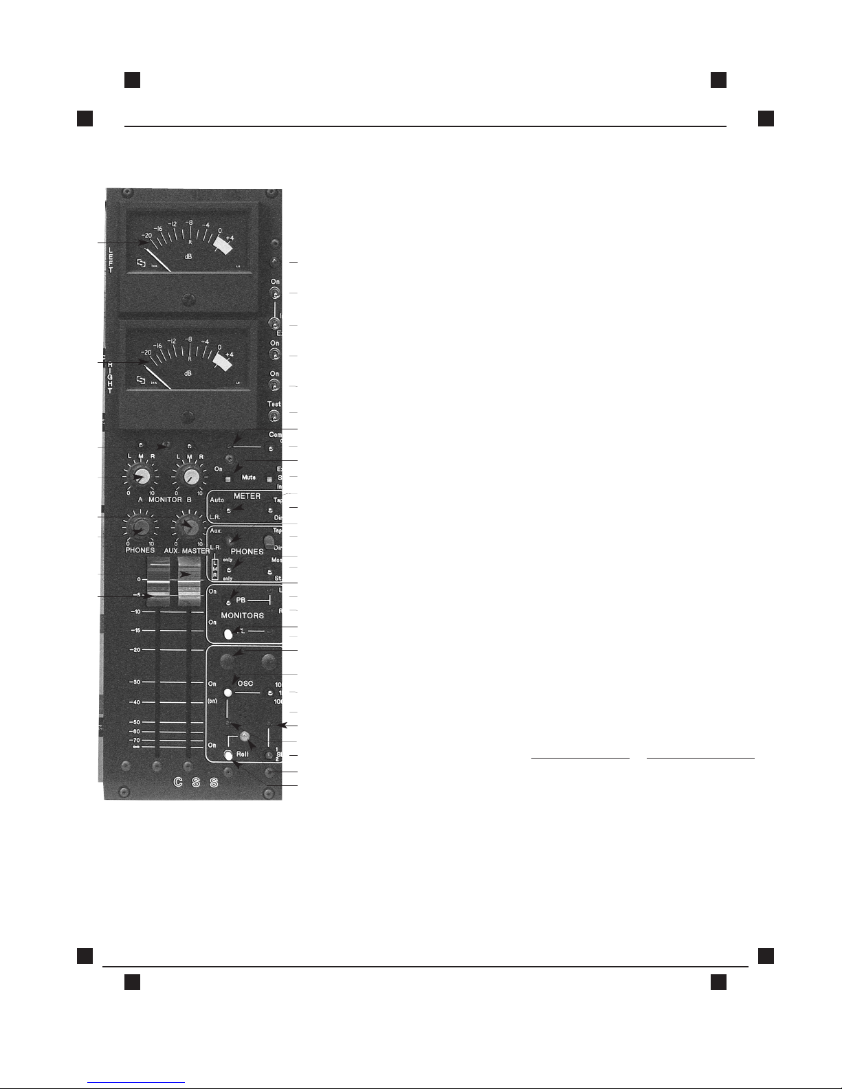
1. LEFT METER: Vu or PPM. Indicates left, Aux., PFL
2. RIGHT METER: Indicates right,aux., PFL and
battery level.
3.MONITORS A & B SELECT: Left only, right only, left and right.
4.MONITORS A & B LEVEL: Mono output
Application: monitor A can be
assigned to boom operators and
monitor B to director / script.
5. AUX. MASTER: Max=nominal level
6. "PHONES" LEVEL: Stereo output
7. RIGHT OUTPUT FADER: Max=nominal level
8. LEFT OUTPUT FADER: Max=nominal level
9. POWER ON LED.
10. POWER ON / OFF.
11. POWER INTERNAL /
EXTERNAL SELECT.
12. PHANTOM POWER ON: To conserve current consumption
when 48v phantom mics are not
used (Does not affect 12v
phantom)
13. LIGHT ON: Switches +12vDC to BNC
connector. May be used to power
a Littlite.
Note: Not recommended to use
Q5 type bulb due to large current
consumption. Ground of BNC is
isolated from chassis. (Do not
ground lamp to chassis)
14. BATTERY TEST: Lower (right) meter measures level
of batteries or external power.
With Vu Meters: With PPM Meters:
0Vu=12v -6=12v
+3Vu=18v +2=18v
1
2
3
4
5
6
7
8
9
10
11
12
13
14
15
16
17
20
22
24
21
19
18
23
25
26
27
28
29
30
31
32
33
34
36
35
37
38

COOPER SOUND SYSTEMS, INC. ■ 1067 MAIN STREET ■ CAMBRIA, CA 93428 ■ (805) 927-8521
OUTPUT MODULE MODELS: CS 106+1
CS 108+1
PAGE 4 ■ JANUARY 1998 ■ REV. 3
15.COMMUNICATIONS TRIMMER: To adjust level of communications signal.
16.COMMUNICATIONS ON/ OFF: Communication input is fed only to "phones." (Line level input)
(eg: Boom operator talkback or cueing)
17. MUTE ON: In "on" position both monitor A & B outputs are muted during slating
and oscillator operation. An internal circuit board switch disables
muting function to monitor A output.
18. SLATE INTERNAL /EXTERNAL: External slate mic may be connected to the slate XLR. Level is
adjusted by (34)
19. "METER" AUTO /LEFT RIGHT: In auto, the meters follow the “phones” selection. ie:Mono / stereo,
L/R, Aux., PFL, Tape/Direct, L only, R only. In the L/R position the meter
indicates left and right signals, controlled by switch #20. (Tape direct)
20. "METER" TAPE /DIRECT.
21."PHONES" AUX. /LEFT RIGHT: Auxiliary signal is fed to both left and right "phones" outputs.
22. "PHONES" TAPE /DIRECT.
23. "PHONES" LEFT,MIX, RIGHT: With switch (21) in L.R., either left only or right only or both are fed
to"phones" outputs.
24. "PHONES"MONO / STEREO.
25. "PLAYBACK: Assigns tape return to monitor A & B outputs.
26. LEFT TAPE RETURN: Level adjust for tape return.
27. RIGHT TAPE RETURN: Level adjust for tape return.
28. PRIVATE LINE: Either internal or external slate mic output is fed to monitor A output.
(Can also be assigned to monitor B, see page 16).
29. PRIVATE LINE LEVEL: Independent of slate level.
30. OSCILLATE ASSIGN: Aux only, L/R only, all outputs
31. OSC. ON: Three-position switch; Up=On Center=Off
Down=Momentarily on
Level is dependent upon master fader positions.
32. OSC. FREQUENCY SELECT: Note: Also controls the frequency of the auto end tones.
33. INTERNAL SLATE MIC.
34. SLATE LEVEL: Controls both internal and external slate levels.
35. OSCILLATOR LEVEL.
36. SLATE ON: Three-position switch; Up =On(no sub-tone) Center=Off
Down=Momentarily on (with subtone)
Also, turns remote roll on (internal switch to defeat, see page 16).
37. ROLL ON LED.
38. ROLL ON: Roll is connected to the tuchel connectors to turn on either a Nagra
4.2 or IVS or both. When the roll switch is turned to off, the recorder will
remain on for ≈1 sec.and two end tones are fed to outputs. This
function can be defeated by a dip switch inside. (See location
diagrams, page 16).
See Specifications on Page 12
PAGE 5 ■ JANUARY 1998 ■ REV. 3
STEREO MODULE MODELS: CS 106+1
CS 108+1
COOPER SOUND SYSTEMS, INC. ■ 1067 MAIN STREET ■ CAMBRIA, CA 93428 ■ (805) 927-8521
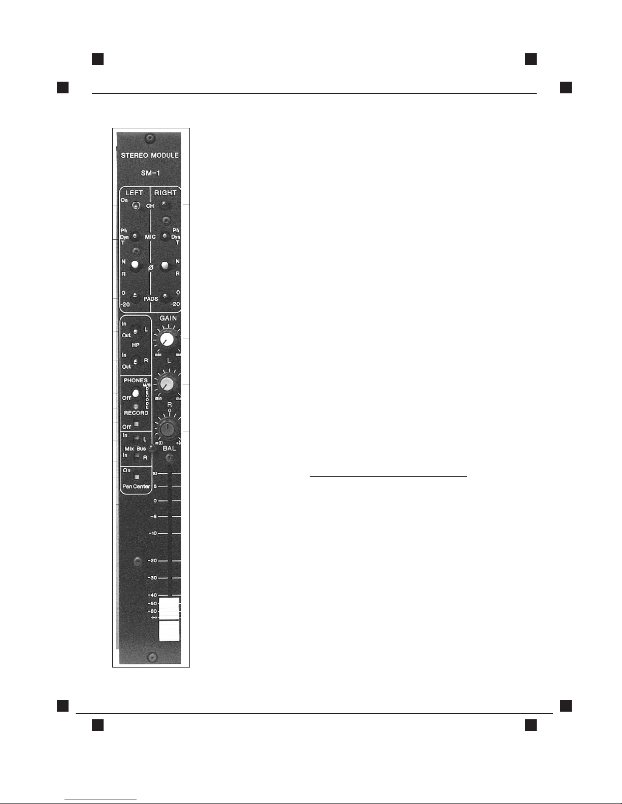
1. CHANNEL POWER.
2. LEFT & RIGHT
MIC POWER SELECT:
Phantom (48v)
Dynamic (no power)
"T" power (A B)
12v phantom may be selected on
circuit board via straps.
3. LEFT & RIGHT PHASE: Audio phase only.
4. LEFT & RIGHT PADS.
5./6. LEFT & RIGHT
HIGH PASS FILTER.
7./8. LEFT & RIGHT PREAMP
GAIN CONTROL.
9. BALANCE / STEREO
WIDTH CONTROL:
With a left, right mic configuration,
the balance of the two channels
can be changed. In M/S
configuration, this control affects
the stereo width: A wider stereo
image is obtained with the control
set towards S.
10.CHANNEL STEREO FADER.
M / S DECODE SECTION:
11. PHONES DECODE: Phones circuit only is switched to
M/S decode. In left, right
operation, this switch should be off.
12. LED: Indicates phones decode on.
13. RECORD DECODE: The output of the stereo module is
decoded (M/S in =L/R out).
14./15. MIX BUS IN / OUT
LEFT & RIGHT: With the mix bus switches out
the line outputs of the stereo
module may be used to feed a
separate recorder without
affecting your main mix. (See
switch combination examples.)
16. PAN CENTER: Monos module outputs
1
2
3
4
5
6
11
12
13
14
15
16
12
7
10
8
9

PAGE 6 ■ JANUARY 1998 ■ REV. 3
STEREO MODULE MODELS: CS 106+1
CS 108+1
COOPER SOUND SYSTEMS, INC. ■ 1067 MAIN STREET ■ CAMBRIA, CA 93428 ■ (805) 927-8521
SWITCH COMBINATIONS
L MIX BUS R MIX BUS PAN CENTER
Ex. 1 In Out Off
Ex. 2 Out In Off
Ex. 3 In In Off
Ex. 4 In In On
Ex. 5 Out Out Off
Ex. 6 Out Out On
Ex. 7 In Out On
Ex. 8 Out In On
Ex. 1 Left mic in is assigned to the left mix bus (right input is not used). This
enables module to be used as a single mono channel. By switching
the unused channel out there will be no additional noise contributed
to the other mix bus.
Ex. 2 As above, with right mic.
Ex. 3 Both inputs are fed to their respective outputs.
Ex. 4 Both module outputs are centered (ie; they are combined and fed
equally to both left and right mix busses and outputs).
Ex. 5 Both outputs are disconnected from the mix busses and fed only to
the module line outs.
(To enable a discrete mix to be made on a separate recorder.)
Ex. 6 As above, but both outputs are combined as in Example 4.
Ex. 7 Left output only is assigned to both left and right mix busses and
outputs.
Ex. 8 As above, with right output.
NOTE: The switches above enable the module to function as a single
channel or as dual mono channels.
SPECIFICATIONS:
PADS: -20 dB
HIGH PASS FILTER: FC=70 HZ, 12 dB/octave.
RESPONSE: 20-20 kHZ +/- 0.5 dB
EIN: 20-20 kHZ better than -128 dBu
THD+N: 20-20 kHZ better than .01%

PAGE 7 ■ JANUARY 1998 ■ REV. 3
AUX MODULE MODELS: CS 106+1
CS 108+1
COOPER SOUND SYSTEMS, INC. ■ 1067 MAIN STREET ■ CAMBRIA, CA 93428 ■ (805) 927-8521
A modular unit that can be installed in the Cooper series 100 location mixers. This
module provides two extra independent balanced outputs (Aux I, I I) that can
be utilized for four track recording
(eg; Nagra D), two stereo mixes or additional
aux. sends.
The CSD-2 includes two P&G faders that are aligned with the existing two output
faders on the master module for easy group fades. Any input channel can be
selected or assigned to the CSD-2 outputs via the aux. module channel select
switches and the pan pots. The aux. outputs can be monitored by the 'phones'
and 'meters' on the output module by selecting 'I, II' on the module.
Mix bus switch on input channels - when switched 'off' the channel line out will
only go to the aux. module outputs allowing separate mixes to be made
independent of the main L, R outputs.
The slate and oscillator from the master module is also connected to the aux.
outs (internal dip switches can defeat this feature). The outputs are via a 5-pin
XLR connector mounted on the rear panel. Adapters to 3-pin XLRs are available.
Pin configuration is standard. (See specifications)
As with all other Cooper Sound products, all components are the best available
to ensure the highest audio quality and reliability in the field.
SPECIFICATIONS
OUTPUTS: +4 dBu balanced
RESPONSE: (20-20 kHZ)
=
+/- 0.5 dB
THD + N: (20-20 kHZ) = 0.01%
(TYP. 0.005%)
XLR-5 CONFIGURATION:
Pin 1 = ground
Pin 2 = I high
Pin 3 = I low
Pin 4 = II high
Pin 5 = II low
 Loading...