

Page 1
I-SD01
Speech Dialler
Installation and
Programming Guide
Page 2
Page 2
Introduction
The I-SD01 module is designed to fit on the I-ON16 control unit.
The I-SD01 allows the control unit to report alarm conditions over
the public switched telephone network (PSTN) using either recorded
speech messages, or SMS (Short Message Service) texts to mobile
telephones by way of the PSTN.
Installation
Preparation
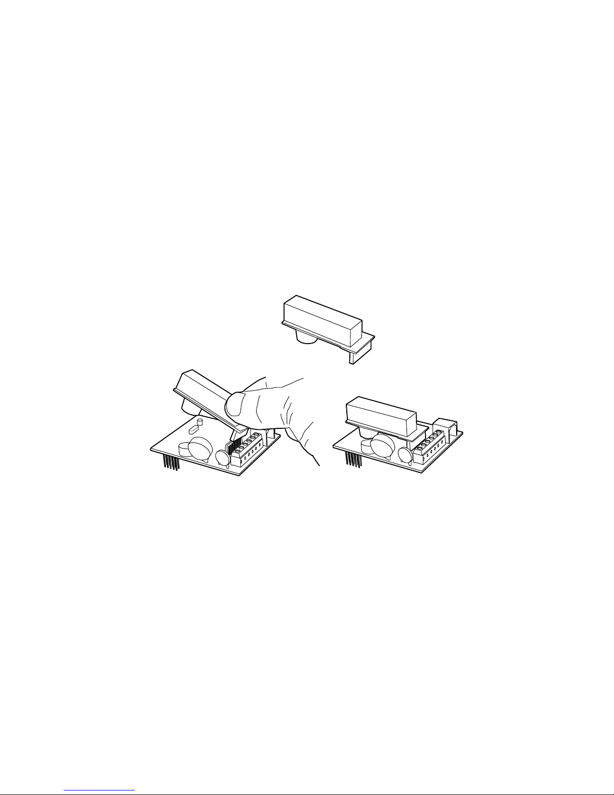
Before fitting the I-SD01 module, check whether the telephone line
you intend to use is shared with an ADSL (broadband) modem. If it
is, then fit filter ADSL01 as shown in Figure 1 .
ADSL01
Figure 1. Fitting ADSL01 to I-SD01
Note: If the telephone line is NOT shared with an ADSL modem
then leave the factory fitted jumpers in place.
Recording Voice Messages
The microphone for recording speech messages is on the I-SD01
module, as well as a small speaker that allows you to playback the
messages.
If you intend to record speech messages, and the user’s keypad is
already fixed at some distance from the central station, you may
wish to temporarily connect a second keypad to the end station.
This will enable you to program the system and easily
record/playback any speech messages.
Page 3

Page 3
Installing the Module in the End Station
1. Remove mains power from the end station.
2. Open the end station lid and disconnect the battery.
3. Fit the I-SD01 to the plug on module sockets (see Figure 2).
Figure 2. Fitting I-SD01 Module
4. Connect the module to the PSTN.
The person connecting the I-SD01 module to the PSTN must be
suitably qualified. Connect the I-SD01 telephone connector (see
Figure 3) ONLY to the PSTN or to other circuits designated as
Telecommunications Network Voltage.
ABCEA1B1
See Note
PSTN
Warning: Telecommunications Network Voltage
A, B Connect to PSTN
A1, B1 Connect to local phone extension (if required)
E For added surge protection connect to a suitable protective earth.
C Note: (UK only) connect to ringing wire from PSTN and to ringing wire on extension
phone, if fitted.
Figure 3. Telephone Connection
Page 4

Page 4
5. If necessary, temporarily connect a keypad.
5. Reconnect the battery.
6. Apply mains power.
Programming
For details on programming the I-SD01 please refer to the
I-ON16 Installation and Programming Guide. All the options
necessary for programming the module are in the Installer Menu
under the Reporting option.
Note: The control unit hides the Reporting option if there is no I-
SD01 fitted.
Finishing the Installation
Once programming is complete:
If you connected a temporary keypad earlier, then remove all
power (mains and battery) before disconnecting the keypad. Reapply mains and battery power afterwards.
NOTE: If you enabled the end station tamper switch to
control speech recording and playback then remember to
disable it BEFORE fitting the end station lid.
Re-fit the lid of the end station.
Test the module using the options in the Installer Menu - Testing
option.
© Cooper Security Ltd. 2008
Every effort has been made to ensure that the contents of this book are correct. However,
neither the authors nor Cooper Security Limited accept any liability for loss or damage caused
or alleged to be caused directly or indirectly by this book. The contents of this book are subject
to change without notice.
Printed and published in the U.K.
This manual applies to software used in the I-ON16 control unit with version 1.xx.xx software.
www.coopersecurity.co.uk
Product Support (UK) Tel: +44 (0) 870 757 5400.
Available between:
08:15 and 17:00 Monday to Friday.
Product Support Fax: (01594) 545401
Part Number 11847980 Issue 1
 Loading...