

Page 1
1
714r
EN
NL
Fr
It
Dk
N
Sv
De
Es
Pt
Page 2

2
Part No. 497358 Issue 1
This product complies with the requirements of European Directive:
1995/5/EC (Radio
&Telecommunications Terminal Equipment Directive).
Page 3
3
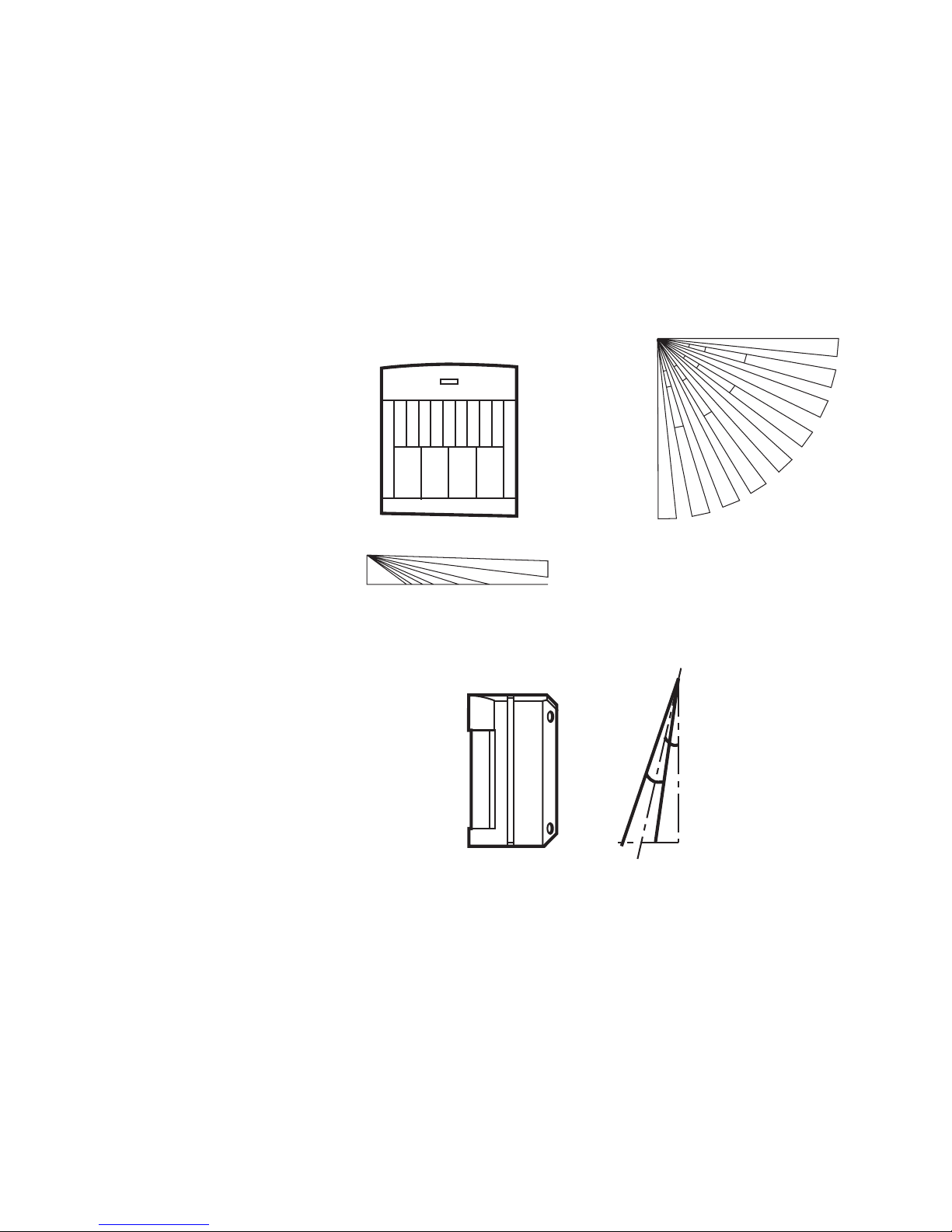
2.4m
(max)
15m
Look down zone
Kruipzone
Zone basse
Melderzone nach unten
Zone Antistrisciamento
Zona de visión hacia abajo
Zona de vigilância
Se ned zone
Se ned sone
Fig. 1
Page 4
4
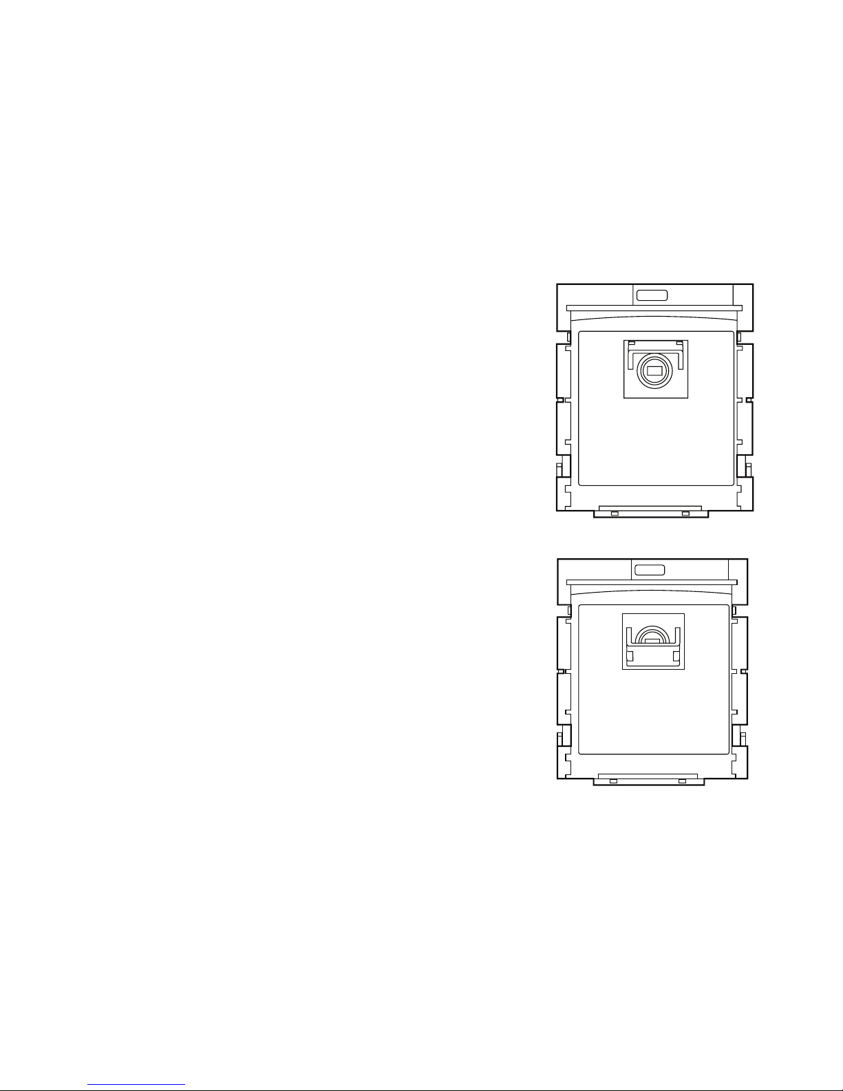
Pet Alley mirror raised
Spiegel kruipzone omhoog
Lentille orientée vers le haut
Angehobener Haustiergassenspiegel
Copertura sollevata
Espejo del callejón de mascotas elevado
Espelho da passagem de animais de estimação levantado
Husdyrspejlet slået op
Husdjurspassage spegel hävd
Husdyrspeil slått opp
Pet Alley mirror lowered
Spiegel kruipzone omlaag
Lentille orientée vers le bas
Gesenkter Haustiergassenspiegel
Copertura abbassata
Espejo del callejón de mascotas bajado
Espelho da passagem de animais de estimação descido
Husdyrspejlet slået ned
Husdjurspassage spegel sänkt
Husdyrspeil slått ned
Fig. 2
Page 5
5
Vertical corner mount
Hoekmontage
Montage en angle droit
Flache Wandmontage
Montaje plano en pared
Montagem em canto vertical
Lodret hjønemontering
Vertikal vägghörn montage
Loddrett hjørnemontering
Flat wall mount
Vlakkewandmontage
Montage en saillie
Vertikale Eckmontage
Montaje vertical en esquina
Montering fladt på væggen
Platt väggmontage
Montering flatt på veggen
Fig. 3
Page 6
6
Wall tamper knock out
Gat tbv wandsabotage
Prédécoupe destinée à un contact d’autoprotection à l’arrachement
Entfernbares Stanzteil für Wand-manipulationsschutz
Foro per Tamper a Parete
Pieza desprendible de interruptor de pared.
Montagem direita na parede
Udstansning til montering af sabotageovervågning på vægen
Våggsabotage utslag
Utstansing for montering av sabotasjeovervåking på veggen
M3 (No4) screw no more than 2.5 mm proud from wall
M3 (No4) schroef niet meer dan 2,5mm uit de muur
Vis M3 (N° 4) ne devant pas dépasser de plus de 2,5 mm du mur
M3-Schraube (Nr. 4); darf nicht mehr als 2,5 mm aus Wand ragen
Vite M3 (No4) non sporgente più di 2.5 mm dalla parete
Tornillo M3 No. 4), sin sobresalir más de 2,5 mm. de la pared.
M3 (Nr. 4) skrue ikke mere end 2,5 mm fra væggenl
M3 (Nr 4) skriva ej längre ur väggen än 2,5 mm
M3 (nr 4) skrue ikke mer enn 2.5 mm fra veggen
Fig. 4
Page 7
7
Fig. 5
Page 8

8
Page 9

9
EN
Introduction
The 714r Passive Infra Red (PIR) is an indoor detector designed to work with Scantronic
868MHz receivers. The PIR detects movement of body heat. The detector has a fan
shaped sensitive area approximately 15 metres in radius. The case is protected by an in
ternal tamper switch. The back of the case can be modified by removing a cutout to provide
a wall tamper.
Specification
Part No. 714rEUR-00
Power Supply 1 x AA 3.6V Lithium cell
Battery Life Approximately 14 months
Operating temp: -10 to +55 °C
Environmental Class I (tested -10 to +55°C)
Low voltage alarm: 2.4V nominal
Lens: Standard 15m x 90 deg.
White light filter: greater than 2000 Lux
RF Immunity: 10V/m
Dimensions: 82mm x 71mm x 47mm x (HxWxD)
Operating Frequency: 868,6625 MHz
Security Grade II
INCERT C0160202
Specification subject to change without notice.
Page 10

10
Siting
You can mount the unit either flat against the wall, or in a corner. The area covered by the
detector is shown in Figure 1.
DO mount the unit between 1.8 and 2.4 metres high for the best general coverage in an
average room.
Do NOT mount the unit:
Facing a fire, boiler or window.
Over a radiator.
Near the floor.
Close to or on large metal structures.
Closer than one metre to mains wiring and metal water or gas pipes.
Inside steel enclosures.
Next to electronic equipment, particularly computers, photocopiers or other radio
equipment.
Closer than 30mm to a ceiling (to allow space for dismounting the unit in the future).
Installation
Open the detector by lifting the flap at the top of the case and removing the screw concealed underneath.
Install one ‘AA’ size 3.6V lithium battery (supplied).
Note: If the transmitter shows a continuously pulsing glow from the activity LED then a fault
has occurred or the battery is totally exhausted. Replace the battery and check that the
activity LED is working normally.
Page 11

11
EN
Pet Alley
1. Remove the PCB from the sensor funnel.
2. Swing down the pet alley mirror (see Figure 2). This deletes all but the top row of the
detector zones.
Note: When using the pet alley mirror mount the detector at 1.6m height in order to main
tain correct coverage with the upper detector zones. Pet immunity extends for 10m. Do not
use this facility in larger areas.
3. Refit the pcb to the sensor funnel .
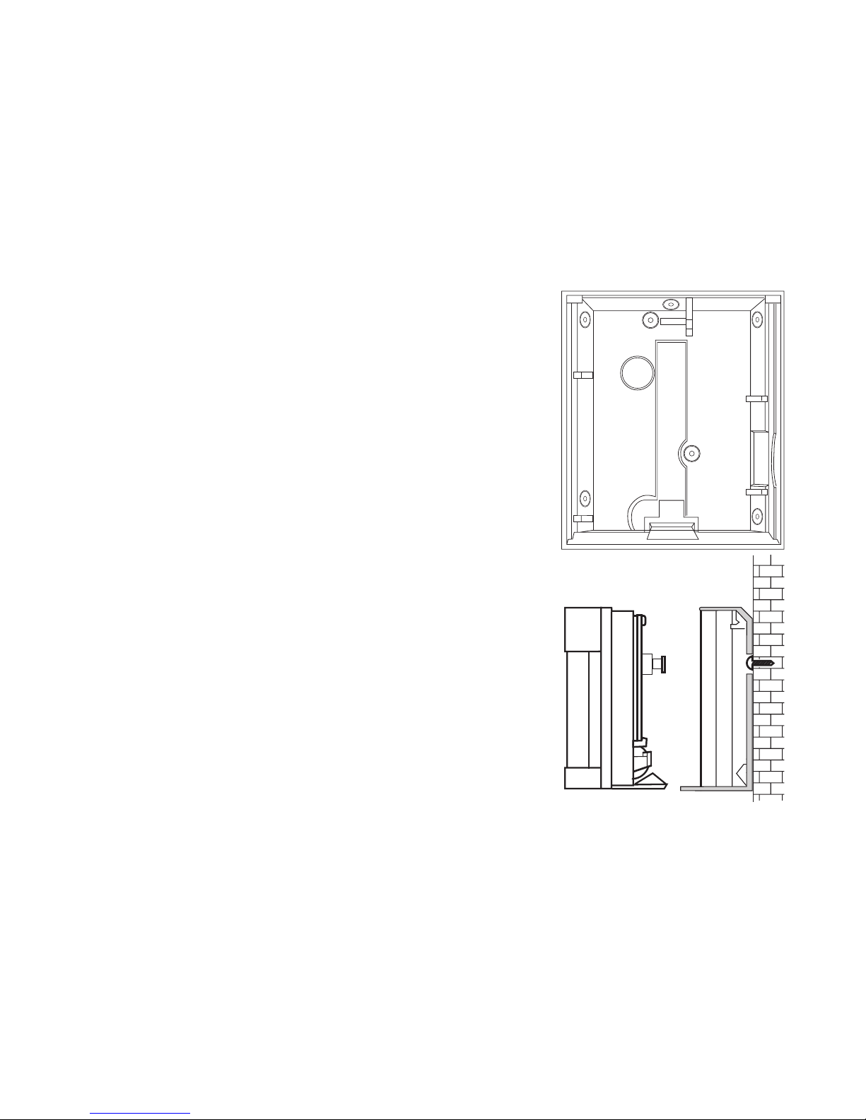
Mount the back
The 714r is designed for mounting by any of the methods shown in Figure 3. The case
back contains a number of possible fixing holes, marked by mouldings in the plastic. Chose
two to suit the location you have selected, and drill them out carefull.
1. Hold the back in location and mark and drill 5mm fixing holes in the wall.
2. Secure the back to the wall with 16mm countersunk head screws and wall plugs.
3. Clip the body of the detector to the back.
Fitting a Wall Tamper
If you wish to fit a wall tamper:
1. Cut out the large circle indicated in the back of the case (see Figure 4).
Make sure that you remove enough material so that the head of the tamper switch can
pass freely through the back of the case.
2. Mark the position of this circle on the wall at the place where the case back will be fit-
ted.
Page 12

12
3. Drill and plug a hole in the wall at the marked position, and insert a M3 (No 4) screw.
Make sure the head of the screw is no more than 2.5 mm from the wall.
Caution: Do not allow the head of the screw to protrude more than 2.5mm from the
wall or you may damage the PIR.
4. Mount the case back so that the head of the screw protrudes through the cut out and
engages the tamper switch when the body of the detector is fitted (see Figure belo).
You may have to adjust the height of the screw until it operates the tamper switch. The
body of the PIR should fit easily into the case back without force.
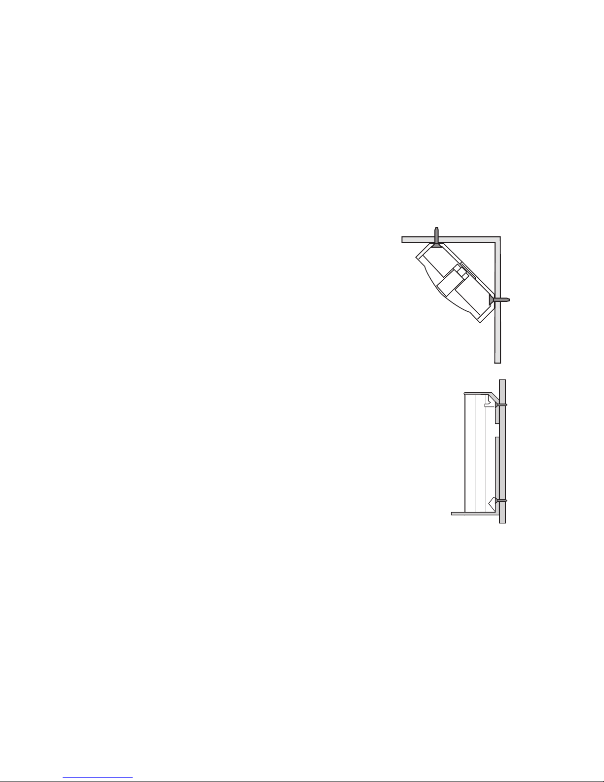
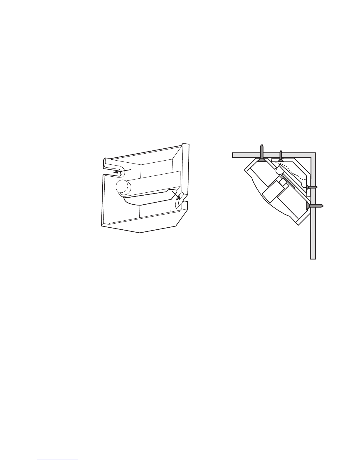
Fitting a Corner Wall Tamper
If you want to fit the 714r in a corner and also fit a wall tamper then you should use the
Scantronic Corner Wall Tamper Bracket (Part No. 235385), see Figure 5.
To fit a wall tamper in a corner mounting:
1. Fit the bracket into the corner. Make sure that it is the correct way up. The stud on the
end of the arm should be at the left.
2. Cut out the large circle indicated in the back of the PIR case. Make sure that you
remove enough material so that the stud of the Wall Tamper Bracket can pass freely
through the back of the case.
3. Fit the PIR case back into the corner on top of the Corner Wall Tamper Bracket. Make
sure the stud on the bracket passes through the hole in the back of the PIR case (see
Figure 5).
4. Fit the body of the PIR to the case back. The body of the PIR should fit easily into the
case back without force.
Page 13

13
EN
Learning
Consult the relevant section in the receiver’s Installation and Programming Guide.
Testing.
1. Put the control unit into walk test.
2. Hold the detector in place.
3. Trigger the detector.
4. Make sure the panel receives the alarm.
5. Chose another site for the detector if the panel does not receive the signal.
6. Stop the walk test at the control unit.
PIR Testing and Lockout
In normal use the 714r uses a lockout timer in order to extend battery life. The lockout timer
works like this:
a) The unit detects movement, signals the panel, and starts the lockout timer.
b) When the lockout timer expires the unit signals the panel the next time it detects move
-
ment.
Cooper Security Ltd set the lockout timer to three minutes when the 714r leaves the fac
tory. If you wish to change the lockout timer to one minute then remove the jumper link
on the back of the PCB. (Replace the link to restore the lockout timer to three minutes.)
Cooper Security Ltd recommends that you leave the jumper fitted. Removing the jumper
for long periods will reduce the life of the battery.
If you want to test a 714r in normal use you should leave the protected area and wait at
least four minutes between activations (two minutes if you have removed the link). To make
Page 14

14
testing easier the detector changes the lockout period to 10 seconds for the first half hour
after you put the battery in, or after you trigger its tamper.
Note: Make sure the control unit is in programming mode before you open or move any
of the detectors. This will avoid setting the tamper alarm off.
When you have fitted and adjusted the 714r test the operation of the complete detector as
follows:
1. Put the control unit into walk test.
2. Clear the protected area and make four random direction walk tests. Using an adult hu
man, walk at a rate of one normal step per second within the detection pattern. The unit
should alarm within three out of the four walk tests.
3. Stand outside the protected pattern and operate any potential cause of false alarm,
e.g., operate lights, open doors, etc. If the unit detects the deliberate cause of false
alarm, try readjusting the detector pattern.
4. Stand outside the detection pattern and observe the detector operation for three to five
minutes without doing anything. The detector should not alarm. If the detector does
alarm, locate the cause and correct it.
Note: When walk testing, cross the sensitive zones at right angles in an upright position.
The LED remains off if the battery has been in for longer than 30 minutes, or if you have
not triggered the detector tamper within the last 30 minutes.
Page 15

15
EN
Maintenance
Inspect the 714r one or more times a year. The inspection should consist of , but be not
limited to, the mounting, the battery, cleaning dust from the lens with a soft cloth, walk test
-
ing and unit operation.
Service
If the transmitter shows a continuously pulsing glow from the activity LED then a fault has
occurred or the battery is totally exhausted. Replace the battery and check that the activity
LED is working normally.
If the activity LED still gives a pulsing glow after inserting a good battery then the unit has
a fault. Return the unit to your supplier.
Page 16

16
© Cooper Security Limited 2005
Every effort has been made to ensure that the contents of this leaflet are correct . How
ever, neither the authors nor Cooper Security Limited accept any liability for loss or damage caused or alleged to be caused directly or indirectly by this leaflet. The contents of this
leaflet are subject to change without notice.
Printed and published in the U.K.
Page 17

17
NL
Introductie
De draadloze passief infrarood (PIR) detector 714r voor binnenshuis, is ontwikkeld voor
toepassing met 868 MHz ontvangers van Scantronic. De PIR detecteert bewegingen van
lichaamswarmte. De detector heeft een waaiervormig detectiegebied met een radius van
circa 15 meter. De behuizing wordt beveiligd door een sabotageschakelaar. Aan de achter
-
kant kan nog een muursabotageschakelaar worden aangebracht.
Specificaties
Artikelnr.: 714rEUR-00
Voeding: Lithium batterij; AA; 3,6VDC
Temperatuurbereik: -10 tot +55 °C
Batterij-laag melding: 2,4V nominaal
Lens: Standaard 15m x 90 graden
Wit licht fileter: meer dan 2.000 Lux
RF Immuniteit: 10V/m
Afmetingen: 82mm x 71mm x 47mm x (HxBxD)
Frequentie: 868,6625 MHz
Milieuklasse I (Getest op -10 tot +55 °C)
Beveiligingsklasse II
INCERT C0160202
Page 18

18
Projectie
U kunt de detector zowel vlak op een muur als in een hoek plaatsen. Hieronder ziet u het
bereik.
Voor het beste resultaat in een gemiddelde ruimte plaatst u de detector op een hoogte van
1,8 tot 2,4 meter.
Plaats de detector NIET:
Gericht op een vuurhaard, boiler, geiser, cv-installatie of raam;
Boven een radiator;
Vlak boven de grond;
Vlak bij grote metalen constructies;
Binnen 1 meter van elektrische leidingen en metalen water- en gasleidingen;
In een stalen omhulsel of kooiconstructie;
Vlak bij elektronische apparatuur zoals computers, faxen en kopieerapparaten;
Minder dan 30 cm van het plafond (U heeft die ruimte minimaal nodig voor
(de)montage).
Installatie
Til de klep aan de bovenkant van de behuizing op en draai de schroef daaronder los. Open
de detector.
Plaats de bijgeleverde Lithium batterij (AA 3,6VDC).
Opm.: Als de LED van de detector regelmatig pulseert wijst dit op een elektronisch mankement of de batterij levert onvoldoende spanning. Vervang de batterij en controleer de LED.
Page 19

19
NL
Kruipzone
1. Neem de PCB uit de houder.
2. Klap de spiegel voor de kruipzone naar beneden. Hierdoor blokkeert u alle detecti
-
ezones behalve de bovenste rij.
Opm.: Als u de kruipzone gebruikt plaatst u de detector op een hoogte van 1,6 meter. Zo
houdt u een juist bereik van de bovenste detectiezones. In deze positie heeft de detector
een bereik van 10 meter. Gebruik deze mogelijkheid niet in grote ruimtes.
3. Plaats de PCB terug in de houder.
Wandmontage
De 714r kan op elk van de onderstaande manieren worden gemonteerd. De achterkant
van de behuizing bevat een aantal voorbewerkte montagegaten. Kies hiervan twee gaten
voor uw lokatie en boor ze voorzichtig uit.
1. Houdt de wandplaat op de gewenste plaats. Markeer en boor 5mm gaten in de muur.
2. Monteer de wandplaat tegen de muur met pluggen en 16mm schroeven.
3. Klik de behuizing van de detector op de wandplaat.
Wandsabotage
Als u een wandsabotageschakelaar wilt aanbrengen:
1. Snij de grote cirkel uit de achterkant van de behuizing (zie hieronder).
Let op dat u voldoende materiaal wegsnijdt, zodat de kop van de sabotageschakelaar
en vrij doorheen kan.
2. Markeer de plaats van de cirkel op de muur.
Page 20

20
3. Boor een gat op de aangegeven plaats en schroef een M3 (nr.4) schroef in een plug.
Let op dat de schroef niet meer dan 2,5mm uit de muur steekt.
Waarschuwing: Als de schroef meer dan 2,5 mm uit de muur steekt beschadigt de
detector.
4. Monteer de behuizing zodanig dat de kop van de schroef door het gat steekt en de
sabotageschakelaar raakt als de behuizing van de detector op de wandplaat is vastgek
-
likt (zie hieronder).
Stel zonodig de afstand van de schroefkop op de juiste lengte in. De detector moet zonder
extra kracht op de wandplaat geklikt kunnen worden.
Hoeksabotage
Als u de 714r in een hoek wilt plaatsen en bovendien een wandsabotageschakelaar wilt
aanbrengen dient u montagebeugel 235385 van Scantronic te gebruiken (zie hieronder).
Als u een wandsabotageschakelaar in de hoek wilt plaatsten:
1. Monteer de montagebeugel in de hoek. Let er op dat de goede kant boven is. De
aanslag op het eind van de arm moet rechts zijn.
2. Snij de grote cirkel uit de achterkant van de behuizing. Let op dat u voldoende materiaal
wegsnijdt, zodat de kop van de sabotageschakelaar en vrij doorheen kan.
3. Monteer de wandplaat van de PIR op de montagebeugel. Controleer of de aanslag van
de montagebeugel door het gat van de wandplaat gaat (zie hierboven).
4. Plaats de PIR op de wandplaat. De detector moet zonder extra kracht op de wandplaat
geklikt kunnen worden.
Page 21

21
NL
Leren
Raadpleeg de Installatie en Programmeer handleiding van de betreffende ontvanger.
Testen
1. Zet het controlepaneel in de looptest.
2. Houdt de detector op de gewenste plaats.
3. Activeer de detector.
4. Controleer of het controlepaneel de alarmmelding ontvangt.
5. Kies een andere plaats voor de detector als het controlepaneel geen signaal ontvangt.
6. Schakel de looptest op het controlepaneel uit.
PIR spaarschakeling en -test
Normaliter gebruikt de 714r een spaarschakeling om de levensduur van de batterijen te
verlengen. Die spaarschakeling werkt als volgt:
1. De detector ‘ziet’ een beweging, geeft een signaal naar het controlepaneel en start de
spaarschakeling.
2. Als de detector een beweging ziet terwijl de timer van de spaarschakeling loopt, dan
start hij de timer opnieuw maar zendt geen signaal naar het controlepaneel.
3. Nadat de periode van de timer is verlopen zal de detector bij de eerstvolgende beweg
-
ing opnieuw een alarmmelding naar het controlepaneel sturen.
Cooper Security zet de spaarschakeling van de 714r op 3 minuten. Als u die periode wilt
wijzigen in 1 minuut dan neemt u de brug van de pennen op de rug van de PCB-kaart.
Plaats de brug weer op de pennen voor een spaarschakeling van 3 minuten. Cooper Se
-
Page 22

22
curity adviseert de brug op de pennen te laten. Als de brug gedurende een lange tijd van
de pennen is (dus spaarschakeling 1 minuut) zal dit ten koste gaan van de levensduur van
de batterijen.
Als u de PIR 714r wilt testen tijdens normaal gebruik gaat u uit de beveiligde ruimte en
wacht daar tenminste gedurende vier minuten tussen twee detecties (twee minuten bij
een spaarschakeling van 1 minuut). Om het testen te vereenvoudigen wijzigt de detector
de periode van de spaarschakeling in 10 seconden gedurende het eerste half uur nadat u
de batterijen in de detector hebt geplaatst, of nadat u de sabotageschakelaar hebt geac
-
tiveerd.
Opm.: Voordat u een detector verplaatst of opent controleert u of op het controlepaneel het
programmeermenu is geopend. Dit voorkomt het uitschakelen van het sabotagealarm.
Als de 714r is gemonteerd en afgeregeld test u de werking van de complete detector als
volgt:
1. Zet het controlepaneel in de looptest.
2. Ruim de beveiligde ruimte op en maak vier looptesten in willekeurige richtingen. De
looptest wordt uitgevoerd door een volwassen persoon met een snelheid van 1 stap per
seconde binnen het detectieveld van de detector. De detector behoort in drie van de
vier gevallen een alarmmelding te geven.
3. Ga buiten het beveiligde gebied staan en creëer een vals alarm door bijvoorbeeld het
licht aan en uit te doen, deuren openen enz. Als de detector hierop reageert probeer
dan het detectiepatroon aan te passen.
Page 23

23
NL
4. Ga buiten het beveiligde gebied staan en observeer de detector gedurende drie tot vijf
minuten zonder iets te doen. De detector behoort geen alarmmelding te geven. Als de
detector dat wel doet, spoor dan de oorzaak op en corrigeer de situatie.
Opm.: Tijdens de looptest doorkruist u de zones rechtop lopend onder rechte hoeken. Na
elke activiteit wacht u totdat de LED is gedoofd. De LED blijft uit als de batterij langer dan
30 minuten actief is geweest, of als u de sabotageschakelaar sinds 30 minuten niet meer
geactiveerd hebt.
Onderhoud
Inspecteer de 714r meerdere keren per jaar. De inspectie dient minimaal te bestaan uit het
controleren van de bevestiging en de batterijen, het stofvrij maken van de lens met een
zachte doek, een looptest en het functioneren van de detector.
Reparatie
Als de LED van de detector continu pulserend brandt wijst dat op een foutmelding of de
batterijen zijn leeg. Vervang de batterijen en controleer of de LED nu wel normaal functi
-
oneert.
Als de LED pulserend brandt nadat u nieuwe batterijen hebt geplaatst functioneert de de
-
tector niet goed. Stuur hem terug naar uw leverancier.
Page 24

24
© Cooper Security Limited. 2005
Alles is in het werk gesteld om er voor te zorgen dat de inhoud van deze handleiding
correct is, fouten en weglatingen uitgezonderd. Echter, noch de samenstellers, noch
Cooper Security zullen enige aansprakelijkheid accepteren voor verlies of beschadiging,
direct of indirect mogelijk door deze handleiding ontstaan. De inhoud van deze handleiding
kan zonder voorafgaande aankondiging aan de laatste stand van zaken worden
aangepast.
Gedrukt en uitgegeven in het V.K.
Page 25

25
Fr
Introduction
Le détecteur à infrarouges passifs (IRP) 714r est un détecteur d’intérieur destiné à être utilisé conjointement aux récepteurs 868 MHz de Scantronic. Le détecteur IRP capte les dé
-
placements de chaleur du corps humain. Sa zone de détection, en forme d’éventail, pos
sède un rayon d’environ 15 mètres. Son boîtier est protégé par un contact d’autoprotection
interne. Un contact d’autoprotection à l’arrachement peut être prévu par simple retrait
d’une prédécoupe prévue à cet effet à l’arrière du boîtier.
Spécifications techniques
Référence produit : 714rEUR-00
Alimentation : 1 pile lithium AA 3,6 V
Température de fonctionnement : -10 à +55 °C
Alarme tension basse : 2,4 V nominal
Lentille : 15 m x 90° (standard)
Filtre lumière blanche : > 2000 Lux
Immunité radio : 10 V/m
Dimensions : 82 x 71 x 47 mm (h x l x p)
Fréquence de fonctionnement : 868,6625 MHz
Classe d’environement : I (Testé de -10 à +55 ° C)
Grade de sécurité : II
INCERT C0160202
Ces spécifications sont susceptibles d’être modifiées sans avis préalable.
Page 26

26
Localisation
Le détecteur peut être monté soit à plat contre un mur, soit dans un angle. La zone de couverture du détecteur est illustrée ci-dessous :
Dans le cas d’une pièce de taille moyenne,
installer le détecteur à une hauteur comprise
entre 1,8 et 2,4 mètres du sol afin d’obtenir une couverture optimale.
NE PAS installer le détecteur :
Face à une source de chaleur, une chaudière ou une fenêtre.
Au-dessus d’un radiateur.
Près du sol.
Sur ou à proximité de larges structures métalliques.
A moins d’un mètre de câbles secteur ou de tuyauteries métalliques d’arrivée d’eau ou
de gaz.
Dans un boîtier métallique.
A proximité de matériel électronique, notamment d’ordinateurs, de photocopieurs ou
autres équipements radio.
A moins de 3 cm du plafond (de façon à laisser suffisamment de place pour son
démontage éventuel).
Installation
Ouvrir le détecteur en soulevant la partie supérieure de son boîtier, puis en retirant la vis
cachée sous ce dernier.
Installer une pile lithium AA 3,6 V (fournie).
Page 27

27
Fr
Remarque : si la LED d’activité de l’émetteur clignote de manière continue, cela signifie
qu’un défaut a été détecté ou que la pile est épuisée. Remplacer cette dernière et vérifier
que la LED d’activité fonctionne correctement.
Passage d’animaux de compagnie
1. Retirer le circuit imprimé de la chambre de protection du capteur.
2. Basculer la lentille de passage d’animaux de compagnie vers le bas. Cette action
supprime toutes les zones de détection, à l’exception des zones supérieures.
Remarque : si cette lentille doit être utilisée, installer le détecteur à une hauteur de 1,6 m
afin de maintenir une couverture correcte des zones supérieures. L’immunité aux animaux
de compagnie s’étend sur 10 mètres. Ne pas utiliser cette fonction sur de plus longues
distances.
3. Replacer le circuit imprimé dans la chambre de protection du capteur.
Installation de l’embase
Le 714r peut être monté en saillie sur une paroi verticale ou en angle, ainsi que l’illustrent
les deux schémas ci-dessous. L’arrière du boîtier (embase) présente un certain nombre de
prédécoupes de fixation possibles, repérées par des moulures dans le plastique. Sélec
-
tionner deux trous en fonction de l’emplacement souhaité, avant de les percer avec soi.
1. Maintenir l’embase en place, effectuer les 2 marquages nécessaires puis percer des
trous de fixation de 5 mm dans le mur.
2. Fixer ensuite l’embase au mur à l’aide de vis à têtes fraisées 16 mm et de chevilles.
3. Clipser enfin le corps du détecteur sur l’embase.
Page 28

28
Installation d’un contact d’autoprotection à l’arrachement
Procéder comme suit pour installer un contact d’autoprotection à l’arrachement :
1. Découper le grand cercle repéré sur l’embase du boîtier (voir la figure ci-dessous) en
veillant à retirer suffisamment de matière pour que la tête du contact d’autoprotection
puisse passer sans problème dans le trou pratiqué dans l’embase.
2. Marquer la position de ce cercle sur le mur, à l’emplacement précis où l’embase du
boîtier doit être installée.
3. Percer et cheviller un trou dans le mur à l’emplacement repéré, puis insérer une vis M3
(N° 4). S’assurer que la tête de la vis ne dépasse pas de plus de 2,5 mm de la paroi
murale.
Attention : au risque d’endommager le détecteur IRP, la tête de la vis ne doit pas
dépasser de plus de 2,5 mm du mur.
4. Positionner le boîtier de sorte que la tête de la vis puisse venir s’insérer dans le cercle
prédécoupé et enclencher le contact d’autoprotection une fois le détecteur installé (voir
les schémas ci-dessou).
Il peut s’avérer nécessaire d’ajuster la hauteur de la vis jusqu’à ce qu’elle soit en mesure
d’activer le contact d’autoprotection. Le corps de l’IRP doit pouvoir être replacé sur
l’embase sans forcer.
Installation en angle d’un contact d’autoprotection à
l’arrachement
S’il est nécessaire d’installer un détecteur 714r en angle et de le pourvoir d’un contact
Page 29

29
Fr
d’autoprotection à l’arrachement, utiliser le support Scantronic approprié (référence
235385). Pour plus de précisions, se reporter à la figure ci-dessou :
Procéder comme suit pour installer un contact d’autoprotection à l’arrachement au sein
d’un détecteur monté en angle :
1. Fixer le support dans l’angle et s’assurer que son orientation est correcte. Le contact
situé à l’extrémité du bras doit se trouver à droite.
2. Découper le grand cercle repéré à l’arrière du boîtier de l’IRP en veillant à retirer suf
fisamment de matière pour que la tête du contact d’autoprotection puisse passer sans
problème dans le trou pratiqué dans l’embase.
3. Fixer l’embase du détecteur dans l’angle, en la positionnant sur le support. Vérifier que
le contact situé sur le support passe sans difficulté dans le trou découpé à l’arrière du
boîtier (voir la figure ci-dessus).
4. Clipser le détecteur sur son embase. Il ne doit pas être nécessaire de forcer pour re
-
fixer le tout.
Apprentissage
Se reporter au chapitre correspondant du Guide d’installation et de programmation du
récepteur utilisé.
Test
1. Placer la centrale en mode de test de passage.
2. Maintenir le détecteur en position.
3. Déclencher le détecteur.
Page 30

30
4. S’assurer que la centrale reçoit bien l’alarme.
5. Dans le cas où la centrale ne reçoit pas le signal, choisir un autre emplacement pour le
détecteur.
6. Sortir la centrale du mode de test de passage.
Test de l’IRP et temporisation de mise en veille
En mode de fonctionnement normal, le 714r utilise une temporisation de mise en veille afin
de préserver sa pile et donc sa longévité. Ladite temporisation fonctionne comme suit :
a) Le détecteur capte un mouvement, envoie un signal à la centrale et lance la temporisa-
tion de mise en veille.
b) Une fois cette temporisation expirée, le détecteur n’envoie pas d’autre signal à la cent-
rale tant qu’il ne capte pas d’autre mouvement.
En sortie d’usine, la temporisation de mise en veille du 714r est de trois minutes. Pour la
réduire à une minute, retirer le cavalier situé à l’arrière du circuit imprimé. Pour restorer
la temporisation initiale de trois minutes, replacer le cavalier. Cooper Security Ltd recom
mande de laisser le cavalier en position. En effet, le retrait de ce dernier pendant de
longues périodes réduit la durée de vie de la pile.
Pour tester un détecteur 714r en cours de fonctionnement normal, il est nécessaire de
quitter la zone protégée et d’attendre au moins quatre minutes entre chaque activation
(deux minutes si le cavalier a été retiré). Pour faciliter l’exécution du test, le détecteur
passe la temporisation de mise en veille à 10 secondes pendant la première demi-heure
suivant la mise en place de la pile ou l’activation du contact d’autoprotection.
Page 31

31
Fr
Remarque : s’assurer que la centrale est bien en mode de programmation avant d’ouvrir
ou de déplacer l’un des détecteurs, ceci afin de ne pas inhiber l’alarme d’autoprotection.
Une fois l’installation terminée, initier un test complet du détecteur 714r en procédant
comme suit :
1. Placer la centrale en mode de test de passage.
2. Quitter la zone protégée et exécuter quatre tests de passage dans n’importe quelle di
rection. Ce test doit être effectué par un adulte se déplaçant à une allure normale dans
la zone de détection. Le détecteur doit déclencher une alarme dans trois des quatre
tests.
3. Demeurer hors de la zone protégée et déclencher diverses fausses alarmes (activer
l’éclairage, ouvrir des portes, etc.). Si le détecteur capte la cause délibérée de la fausse
alarme, essayer de modifier sa couverture.
4. Se tenir hors de la zone de couverture du détecteur et observer le fonctionnement de
celui-ci pendant trois à cinq minutes sans initier la moindre action. Normalement, le
détecteur ne doit pas déclencher d’alarme. Si tel est néanmoins le cas, déterminer la
cause du déclenchement et la corriger.
Remarques :
1. Durant le test de passage, traverser les zones de détection à angle droit en se tenant
debout et droit.
2. La LED reste éteinte si la pile est dans l’appareil depuis plus de 30 minutes ou bien si
l’autoprotection du détecteur n’a pas été déclenchée dans les 30 dernières minutes.
Page 32

32
Entretien
Vérifier le bon fonctionnement du 714r au moins une fois par an. Cette vérification doit
comprendre les points suivants, sans pour autant s’y limiter : l’installation, l’état de la pile,
le nettoyage de la poussière déposée sur la lentille à l’aide d’un chiffon doux, l’exécution
de tests de passage et le fonctionnement du détecteur.
Maintenance
Le clignotement continu de la LED d’activité indique la présence d’un défaut ou que la pile
est totalement hors service. Remplacer cette dernière et vérifier que la LED d’activité fonc
-
tionne de nouveau normalement.
Si la LED continue de clignoter après que la pile ait été changée, cela signifie que le dé
-
tecteur est défectueux. Dans ce cas, retourner l’appareil au fournisseur.
© Cooper Security Limited 2005
La plus grande attention a été apportée à l’exactitude des informations contenues dans
ce document. Les auteurs de cette notice ainsi que la société Cooper Security Limited
déclinent toute responsabilité en cas de pertes ou de dommages provoqués ou supposés
avoir été provoqués directement ou indirectement par ce guide. Par ailleurs, le contenu de
ce document est susceptible d’être modifié sans avis préalable.
Page 33

33
It
Introduzione
Il sensore ad infrarossi passivi (PIR) 714r è stato progettato per esser compatibile con tutti
i ricevitori Scantronic a 868MHz (9955-xx, 9960-xx, 768r/769r, 762r ed il sistema radio Ho
melink 75). Il sensore rileva il calore di un corpo in movimento all’interno del proprio campo
di copertura di circa 15 metri. Il contenitore è protetto da un interruttore Tamper mentre
sulla parte posteriore è possibile aggiungere un dispositivo antimanomissione da parete.
Specifiche
Codice 714rEUR-00
Copertura 15m
Periodo di Allarme 2 secondi
Lente Standard 15m x 90 gradi.
Regolazione Lente 10 gradi verticali
Filtro Luce Bianca maggiore di 2000 Lux
Immunità RF 20V/m
Frequenza 868,6625 MHz - FM - Banda Stretta 20 KHz
Potenza 10 mW
Temp. Esercizio da -10 a +55 °C
Dimensioni 71mm(L)x82mm(A)x47mm(P)
Alimentazione Batterie 1 x AA 3,6 V Litio
Allarme Batteria Bassa 2.4V nominali
Peso 20 g
Specifiche soggette a cambiamento senza preavviso.
Page 34

34
Posizionamento
Il rivelatore può essere montato a parete o ad angolo. L’area di copertura è mostrata in
figura 4.
Installare il sensore tra 1.8 e 2.4 metri di altezza da pavimento per assicurare la migliore
copertura possibile.
NON installare il rivelatore:
- Frontalmente a finestre, termosifoni, fonti di condizionamento.
- Sopra a radiatori.
- In prossimità del pavimento.
- Vicino o sopra ampie superfici metalliche.
- Vicino a meno di un metro da tubature dell’acqua o gas.
- All’interno di armadi in acciaio.
- Vicino ad attrezzature elettroniche come computer, fotocopiatrici
- A meno di 30mm dal soffitto (per consentire la disinstallazione del sensore in futuro).
Installazione
Aprire il sensore ed inserire la batteria tipo ‘AA’ fornita
Nota: Se il sensore attiva il LED in modo lampeggiante identifica che è presente un
guasto o le batterie sono totalmente esauste. Sostituire le batterie e verificare che il LED
funzioni regolarmente.
Page 35

35
It
Immunità Animali
1. Rimuovere il circuito dal contenitore.
2. Abbassare la coprtura per l’immunità agli animali. Questa operazione elimina le zone di
rilevazione inferiori.
Nota: Quando si utilizza la copertura per l’immunità agli animali, installare il sensore a
1.6m di altezza in modo da mantenere la copertura mediante le zone superiori. L’immunità
agli animali si estende per circa 10 metri.
3. Riposizionare la scheda nel contenitore.
Installazione del contenitore
Il 714r è progettato per essere installato nelle due modalità mostrate sotto. La parte posteriore del contenitore è dotato di numerose predisposizioni per il fissaggio a parete o ad
angolo. Scegliere il tipo di installazione e forare le predisposizioni attentamente.
1. Tenere la parte posteriore e forare la parete con fori da 5mm.
2. Assicurare la parte posteriore alla parete tramite viti lunghe16mm.
3. Agganciare il sensore sulla parte posteriore.
Installazione del Tamper a parete
Se si desidera installare il Tamper a parete:
1. Forare la parte posteriore del sensore dove indicato (vedere Figura 5).
Il foro deve essere sufficientemente largo da consentire il passaggio della testa del
Tamper attraverso la parte posteriore del contenitore.
2. Marcare la posizione del foro sulla parete.
Page 36

36
3. Forare ed inserire una vite M3 (No 4). Assicurarsi che la testa della vite non sia spor-
gente più di 2.5 mm dalla parete.
Attenzione: La testa della vite non deve essere sporgente più di 2.5mm dalla
parete per non danneggiare il sensore.
4. Installare la parte posteriore del sensore in modo che la testa della vite attraversi il
foro per allinearsi sull’interruttore Tamper quando tutto il sensore viene chiuso (vedere
Figura 6).
E’ possibile regolare l’altezza della vite per assicurarsi che vada a chiudere l’interruttore
Tamper. Il sensore dovrebbe essere inserito facilmente sul retro del contenitore.
Installazione del Tamper ad angolo
Se si desidera installare il 714r nella posizione ad angolo, utilizzare l’apposito snodo opzionale (Part No. 235385) come mostrato in Figura 8.
Per utilizzare il tamper in una installazione ad angolo:
1. Posizionare lo snodo nell’angolo nella posizione corretta. Assicurarsi che la borchia
sulla destra come mostrato in Figura 7.
2. Forare la parte posteriore del contenitore del sensore come mostrato in Figura 5 per
agevolare il passaggio della borchia.
3. Installare il sensore nella parte posteriore dalla estremità superiore dello snodo assicu
-
randosi che la borchia passi agevolmente nel foro fatto in precedenza (vedere Figura
8).
4. Assicurare il sensore al retro del contenitore.
Page 37

37
It
Apprendimento
Vedere il manuale di installazione dei ricevitori al capito “Apprendimento Trasmettitori”
Test
1. Predisporre la centrale o il ricevitore in Test di Copertura.
2. Allarmare il sensore.
3. Assicurarsi che l’allarme sia ricevuto.
4. Scegliere un’altra posizione per il sensore se il segnale non è stato ricevuto.
5. Terminare il Test di Copertura.
Test del Sensore PIR e Timer Blocco Trasmissione
Durante il normale impiego, il sensore 714r utilizza un timer di blocco della trasmissione
radio in modo da estendere la durata delle batterie. Il timer di Blocco funziona nel
seguente modo:
a) L’unità rileva del movimento, invia la segnalazione alla centrale ed attiva il Timer di
Blocco.
b) Ad ogni rilevazione successiva durante questo timer, NON corrisponde alcuna
trasmissione verso la centrale.
c) Non appena il Timer di Blocco si esaurisce, alla prima rilevazione corrisponde
nuovamente una trasmissione di allarme verso la centrale
Cooper Security Ltd imposta il Timer di Blocco a tre minuti. Se si desidera modificare il
timer ad un minuto, rimuovere l’apposito ponticello posto nella parte posteriore della sche
da. (Ripristinare il ponticello per impostare il Timer di Blocco a tre minuti). Cooper Security
Ltd raccomanda di lasciare il ponticello inserito per prolungare la durata delle batterie.
Page 38

38
Se si desidera eseguire un test durante il normale impiego del sensore, lasciare l’area protetta per almeno 4 minuti dalla ultima rilevazione (2 minuti se il ponticello è stato rimosso).
Per facilitare il test, il sensore modifica il Timer di Blocco a 10 secondi per i primi 30 minuti
dopo l’inserimento delle batterie o dopo l’attivazione del tamper.
Nota: Assicurarsi che la centrale sia in programmazione prima di aprire un sensore per
evitare attivazioni acustiche dovute all’allarme Tamper.
Quando il 714r è stato installato, completare le operazioni come segue:
1. Attivare la funzione di Test Copertura
2. Abbandonare l’area protetta ed attendere il termine del Timer di Blocco. Entrare
nell’area protetta da tutte le direzioni possibili camminando all’interno del campo di
copertura del sensore.
3. Rimanere all’esterno dell’area protetta ed attivare le fonti di potenziali falsi allarmi come
luci, termosifoni, bocchette di condizionamento, ecc. Se il sensore dovesse rilevare
un allarme, procedere ad un riposizionamento del sensore per una diversa copertura
dell’area.
4. Rimanere all’esterno dell’area protetta ed osservare il comportamento del sensore per
almeno 5 minuti per verificare che non segnali nuovamente un allarme.
Nota: Durante il test di copertura del sensore, attendere lo spegnimento del LED tra un
test e l’altro.
Page 39

39
It
Manutenzione
Ispezionare il 714r una o più volte durante l’anno. L’ispezione consiste nella verifica della
installazione, funzionamento batterie, pulizia della lente dalla polvere e test di copertura,
Assistenza
Se l’unità attiva continuamente il LED in modo lampeggiante identifica la presenza di
una anomalia o la totale scarica delle batterie. Sostituire le batterie e verificare il normale
funzionamento del sensore.
Se il LED si attiva ancora in modo lampeggiante, consegnare l’unità al proprio formitore.
Page 40

40
© Cooper Security Limited 2005
Ogni sforzo è stato compiuto per garantire la correttezza dei contenuti del presente testo.
Tuttavia, gli autori e la Cooper Security Limited non accettano responsabilità per perdite o
danni causati o presumibilmente causati dal presente testo direttamente o indirettamente.
Il contenuto del testo è soggetto a modifiche senza preavviso.
Stampato e pubblicato nel Regno Unito.
Page 41

41
Dk
Indledning
714r PIR er en passiv infrarød (PIR) indendørs detektor designet til at virke sammen med
Scantronic 868MHz modtagere. PIR detekterer på bevægelser i kropsvarmen. Detektoren
har et vifteformet følsomhedsområde på ca. 15 meter i radius. Kabinettet er beskyttet mod
åbning via en intern sabotagekontakt. Bagsiden af kabinettet kan ændres ved at fjerne
udstansningen for at give plads til en sabotageknap på væggen.
Specifikationer
Varenr.: 714rEUR-00
Strømforsyning: 1 x AA 3,6V litiumbatteri
Driftstemperatur: -10° - +55° C
Miljøklasse: I (testet fra -10
° - +55° C)
Batterialarm: 2,4V nominel
Linse: Standard 15m x 90
°
Hvid lys filter: > 2000 Lux
RF immunitet: 10V/m
Driftsfrekvens: 868.6625 MHz
Sikkerhedsklasse: II
INCERT C0160202
Specifikationerne kan ændres uden varsel.
Page 42

42
Montering
Detektoren kan monteres direkte fladt på væggen eller i et hjørne. Dækningsområde som
beskyttes af detektoren kan ses nedenfor.
MONTÈR detektoren imellem 1,8 og 2,4 meters højde for at opnå den bedste generelle
dækning af rummet.
MONTÈR IKKE detektoren på følgende måder:
Imod brændeovne, kedler eller vinduer.
Over en radiator.
I nærheden af gulvet.
Nær eller på store metalarealer.
Tættere end én meter fra 230Vac kabler og metal- og gasrør.
Indvendigt i et metalrum.
Ved siden af elektronisk udstyr, særligt computere, kopimaskiner eller andet
radioudstyr.
Tættere end 30 mm til et loft (for at gøre plads til at detektoren kan afmonteres).
Installering
Åben detektoren ved at løfte flappen i toppen af kabinettet og afmontér den skjulte skrue i
bunden af hullet. Indsæt ét ’AA’ litiumbatteri (medfølger).
NB! Hvis senderen blinker konstant fra Aktivitets LED’et, er der opstået en fejl i senderen
eller også er batteriet opbrugt. Skift batteriet og tjek at Aktivitets LED’et fungerer rigtigt.
Page 43

43
Dk
Husdyr linse
1. Fjern PCB’et fra sensoren.
2. Vip husdyrspejlet ned. Dette vil bevirke, at alle på nær den øverste række af detektor
-
zoner afblændes.
NB! Når husdyrspejlet benyttes, skal detektorens monteringshøjde være 1,6 mm for at
opnå den bedste detekteringsevne med de øverste detektorzoner. Ved brug af husdyrspe
-
jlet nedsættes rækkevidde til 10 m. Benyt ikke husdyrspejlet i større områder.
3. Genmontér PCB’et i sensoren.
Montering af bagstykke
714r er konstrueret således, at man som vist nedenfor altid kan opnå den bedste montering. Detektorens bagstykke indeholder et antal mulige monteringshuller, der er afmærket
i plasten. Vælg to af dem, der passer bedst til det valgte monteringssted og pres dem
forsigtigt ud.
1. Hold detektorens bagstykke op mod det ønskede monteringssted. Afmærk og bor to 5
mm monteringshuller i væggen.
2. Fastgør bagstykket til væggen med de medfølgende 16 mm forsænkede skruer og
rawplugs.
3. Klik detektorfronten på bagstykket.
Montering af sabotageovervågning på væggen
Ønsker man at montere sabotageovervågning på væggen,
1. Fjern den store cirkulære udstansning i bagstykket (se fig. nedenfor). Vær sikker på at
Page 44

44
der fjernes nok af materialet således, at hovedet på sabotagekontakten frit kan gå igennem hullet i bagstykket.
2. Afmærk positionen af dette hul på væggen, hvor bagstykket skal monteres.
3. Bor ét hul, montér plugsen og skru en M3 (nr. 4) skrue i. Vær sikker på at skruehovedet
ikke er mere end 2,5 mm fra væggen.
Vigtigt! Lad ikke skruehovedet stikke mere end 2,5 mm ud fra væggen, ellers kan
detektorens PIR blive beskadiget.
4. Montér bagstykket således, at skruehovedet stikker ud af udstansningen og kan akti
-
vere sabotagekontakten, når detektorfronten er monteret (se fig. nedenfor).
Det kan være nødvendigt at justere afstanden på denne skrue, indtil sabotagekontakten
aktiveres. Detektorens front må ikke presses ud med vold.
Hjørnemontering med sabotageovervågning
Hvis 714r skal monteres i et hjørne og samtidig benytte sabotagefunktionen, bør man
benytte Scantronic’s hjørnebeslag (varenr. 235385). Fig. nedenfor viser beslaget.
Montering af sabotagefunktionen i et hjørne:
1. Montér beslaget i hjørnet. Vær sikker på at den rigtige side er opad således, at hovedet
på sabotagearmen vender til højre.
2. Fjern den store cirkulære udstansning i bagstykket af PIR kabinettet. Vær sikker på at
der fjernes nok af materialet således, at hovedet på sabotagebeslaget frit kan gå igen
-
nem hullet i bagstykket.
3. Montér detektorens bagstykket i hjørnet oven på beslaget. Vær sikker på at hovedet på
sabotagebeslaget frit kan gå igennem hullet i bagstykket (se fig. nedenfor).
Page 45

45
Dk
4. Montér detektorfronten på bagstykket. Detektorfronten må ikke presses på bagstykket
med vold.
Indlæsning af detektoren
Se det relevante afsnit i modtagerens installerings- og programmeringsvejledning.
Afprøvning
1. Sæt betjeningsenheden i ”Gå test”.
2. Hold detektoren på plads.
3. Aktivér sabotagefunktionen.
4. Sørg for at betjeningsenheden modtager signalet.
5. Vælg et andet monteringssted for detektoren, hvis betjeningsenheden ikke modtager
signalet.
6. Stop ”Gå testen” fra betjeningsenheden.
PIR afprøvning og blokering
Ved normalt brug benytter 714r en blokeringsfunktion for at forøge batteriets levetid. Blokeringsfunktionen virker som følger:
a) Enheden detekterer en bevægelse, sender et alarmsignal og aktiverer blokeringsfunk-
tionen.
b) Når blokeringstimeren udløber, vil detektoren afsende et alarmsignal næste gang de
-
tektoren aktiveres.
Cooper Security Ltd. har forudindstillet blokeringstimeren til 3 minutter. Hvis man ønsker
at ændre blokeringstimeren til 1 minut, skal jumperen på bagsiden af PCB’et fjernes. (Sæt
Page 46

46
jumperen tilbage for at vende tilbage til 3 minutter). Cooper Security Ltd. anbefaler, at man
lader jumperen sidde. Ved at fjerne jumperen i længere tid, vil batteriets levetid reduceres.
For at teste 714r under normalt brug skal man forlade det beskyttede område i mindst 4
minutter (eller 2 minutter hvis jumperen er fjernet), før detektoren kan aktiveres igen. For
at opnå en nemmere afprøvning kan blokeringstimeren ændres til 10 sekunder i den første
halve time efter at batterierne er sat i eller sabotagekontakten er aktiveret.
NB! Vær sikker på at betjeningsenheden er i programmeringsmenuen, før detektorerne
åbnes eller flyttes. Derved undgås at sabotagealarmen aktivers.
Når 714r er monteret og justeret, bør detektoren testes som følger:
1. Sæt betjeningsenheden i ”Gå test”.
2. Ryd det beskyttede område og udfør 4 gå tests i tilfældige retninger. Et voksent men
neske kan udføre testen ved at gå ind i et detektionsområde med normal gang. Enheden bør aktivere alarmen i tre ud af fire gå tests.
3. Stå udenfor det beskyttede område og find ud af en mulig årsag til en falsk alarm, f.eks.
lys, åbne døre osv. Hvis enheden detekterer den forsætlige årsag til en falsk alarm, bør
man forsøge at justere detektionsområdet.
4. Stå udenfor detektionsområdet og iagttag detektoren i 3-4 minutter uden at gøre noget.
Detektoren bør ikke alarmere. Hvis detektoren aktiverer en alarm, find årsagen og afhjælp den.
NB! Når en gå test udføres, skal man aktivere detektorernes zoner ved at gå på tværs i
opret stilling.
Page 47

47
Dk
LED’et forbliver slukket, hvis batteriet har siddet længere end 30 minutter eller hvis sabotagenfunktionen ikke har været aktiveret inden for den sidste halve time.
Vedligeholdelse
714r detektoren skal efterses én eller flere gange om året. Inspektionen bør bestå af, men
ikke være begrænset til, montering, batterier, rengøring af linse for støv med en blød klud,
gå test og drift af enheden.
Service
Hvis senderen blinker konstant fra Aktivitets LED’et, er der opstået en fejl eller også er batteriet totalt opbrugt. Udskift batteriet og tjek at Aktivitets LED’et fungerer korrekt.
Hvis Aktivitets LED’et stadig blinker konstant efter udskiftning af batterierne, er der opstået
en fejl i enheden. Enheden bør returneres til forhandleren.
Page 48

48
©Cooper Security Limited 2005
Alle bestræbelser er gjort for at sikre, at indholdet af denne brochure er korrekt. Hverken
forfatterne eller Cooper Security Limited påtager sig dog ansvar for tab eller skade, der er
forårsaget eller hævdet forårsaget direkte eller indirekte af denne brochure. Vi forbeholder
os ret til at ændre indholdet uden varsel.
Trykt og udsendt i UK.
Page 49

49
N
Innledning
714r Passiv infrarød (PIR) er en innendørs detektor, som er utformet til å arbeide sammen
med Scantronic 868MHz mottakere. PIR registrerer forandringer i kroppstemperaturen.
Detektoren har et vifteformet registreringsområde med en radius på ca. 15 meter. Boksen
er beskyttet av en innvendig sabotasjebryter. Baksiden på boksen kan endres ved å fjerne
en utskjæring for å anbringe en veggmontert sabotasjebryter.
Spesifikasjoner:
Del nr.. 714rEUR-00
Strømforsyning 1 x AA 3.6V Litium celle
Batteriets levetid Cirka 14 måneder
Driftstemp.: -10 til +55 °C
Miljøklasse I (testet -10 til +55 °C)
Alarm for lav spenning: 2.4V nominell
Linse: Standard 15m x 90 grader
Hvitlysfilter: større enn 2000 Lux
RF Immunitet: 10V/m
Dimensjoner: 82mm x 71mm x 47mm x (HxBxD)
Driftsfrekvens: 868,6625 MHz
Sikkerhetsgrad II
INCERT C0160202
Spesifikasjonene kan endres uten varsel.
Page 50

50
Plassering
Enheten kan plasseres enten flatt på veggen eller i et hjørne. Det området, som dekkes av
detektoren, er vist nedenfor.
Enheten SKAL anbringes i mellom 1.8 og 2.4 meters høyde for å oppnå den beste gene
-
relle dekningen i et gjennomsnitsrom.
Enheten MÅ IKKE anbringes:
Med front mot et ildsted, en kjele eller et vindu.
Over en radiator.
Tett på gulvet.
Tett på eller på store metallkonstruksjoner.
Tettere enn en meter på hovedkabler og vann- eller gassledninger av metall.
Inne i stålinnfatninger.
Ved siden av elektronisk utstyr, spesielt komputere, fotokopimaskiner eller annet
radioutstyr.
Tettere enn 30mm fra et tak (for å sikre plass til å ta ned enheten på et senere
tidspunkt).
Installasjon
Detektoren åpnes ved å løfte opp flappen oppe på boksen og fjerne den skruen, som er
fastgjort på undersiden.
Anbring et ”AA” størrelse 3.6V litiumbatteri (levert).
Page 51

51
N
Bemerk: Hvis senderen viser en uavbrutt pulsende glød fra aktivitets-LED’en, så dreier
det seg om en feil eller at batteriet er helt flatt. Utskift batteriet og kontroller, at aktivitetsLED’en fungerer normalt.
Linse til registrering av husdyr
1. Fjern PCB’en fra føleren.
2. Drei ned husdyrspeilet. Dette sletter alt unntatt den øverste rekken av detektorområdene.
Bemerk: Når husdyrspeilet brukes, skal detektoren anbringes i en høyde på 1.6m for å
bibeholde korrekt dekning med de øverste detektorområdene. Husdyrimmuniteten strekker
seg over 10 m. Denne fasiliteten skal ikke brukes på større områder.
3. Gjenanbring PCB’en på føleren.
Montering av baksiden
714r er utformet til å anbringes ved hjelp av en hvilken som helst av de nedenfor viste
metodene. Baksiden på boksen har et vist antall fastgjøringshuller, som er merket ved
støpningen i plastmaterialet. Velg to stykker, som passer til det stedet, du har valgt, og bor
dem ut forsiktig.
1. Hold baksiden på plass og merk og bor 5mm fastgjøringshuller i veggen.
2. Fastgjør baksiden på veggen med 16 mm undersenkede skruer og veggplugger.
3. Klips detektorkroppen fast på baksiden.
Page 52

52
Montering av en sabotasjebryter
Hvis du gjerne vil fastgjøre en veggsabotasjebryter:
1. Skjær ut den store ringen, som er vist på baksiden av boksen (se nedenstående tegn
-
ing).
Vær sikker på, at du fjerner nok materiale til at sabotasjebryteren kan passere fritt igjen-
nom baksiden av boksen.
2. Avmerk ringens posisjon på veggen på det stedet, der baksiden på boksen skal plas
-
seres.
3. Bor og stopp til et hull i veggen på den merkede posisjonen og sett inn en M3 (Nr. 4)
skrue. Sørg for, at skruehodet ikke er lengre end 2.5 mm fra veggen.
Pass på: Skruehodet må ikke gå mer enn 2.5 mm inn fra veggen, da du ellers risikerer å
ødelegge PIR’en.
4. Anbring boksen igjen, slik at skruehodet går inn igjennom utskjæringen og i inngrep
med sabotasjebryteren, når detektorkroppen har blitt anbrakt. (se nedenstående tegn
-
ing).
Det kan bli nødvendig å justere høyden på skruen, til den aktiverer sabotasjebryteren. PIR
kroppen skal passe lett inn i boksens bakside uten bruk av tvang.
Montering av en sabotasjebryter i et hjørne
Hvis man ønsker å plassere 714r i et hjørne og også å plassere en veggsabotasjebryter,
så skal man bruke Scantronic Corner Wall Tamper Bracket (veggbøyle, del nr. 235385).
Nedenstående tegning viser denne delen.
Page 53

53
N
1. Sett bøylen inn i hjørnet. Vær sikker på, at den har den riktige siden opp. Beslaget for
enden av armen skal være til venstre.
2. Skjær ut den store ringen, som er vist på baksiden av PIR boksen. Sørg for å fjerne nok
materiale til at beslaget på veggbøylen kan passere fritt igjennom baksiden av boksen.
3. Sett PIR-boksen tilbake igjen i hjørnet på toppen av Corner Wall Tamper Bracket. Vær
sikker på, at beslaget på bøylen passerer igjennom hullet på baksiden av PIR-boksen
(se ovenstående tegning).
4. Plasser PIR-kroppen på baksiden av boksen. PIR-kroppen skal passe lett inn i bok
-
sens bakside uten bruk av tvang.
Innlesing
Les det pågjeldende avsnittet i installasjons- og programmeringsveiledningen til mottakeren.
Testing
1. Sett kontrollenheten på ”gå-test”.
2. Hold detektoren på plass.
3. Aktiver detektoren.
4. Vær sikker på, at panelet tar imot alarmen.
5. Velg et annet sted til detektoren, hvis panelet ikke tar imot signalet.
6. Stopp ”gå-testen” på kontrollenheten.
Page 54

54
PIR-Testing og Lockout
Ved normal bruk bruker 714r en lockout tidsmåler for å gi batteriet en lengre levetid. Lockout tidsmåleren virker på følgende måte:
a) Enheten registrerer bevegelser, gir signal til panelet og starter lockout tidsmåleren.
b) Når lockout tidsmåleren utløper, sender enheten et signal til panelet neste gangen den
registrerer en bevegelse.
Cooper Security Ltd har satt lockout tidsmåleren på tre minutter, når 714r forlater fabrik
ken. Hvis man ønsker å endre lockout tidsmåleren til et minutt, så fjern koblingsleddet på
baksiden av PCB’en. (Utskift leddet for å sette lockout tidsmåleren tilbake til tre minutter.)
Cooper Security Ltd anbefaler, at man lar leddet bli sittende i. Hvis man fjerner koblingsled
-
det i for lang tid, så blir batteriets levetid redusert.
Hvis man gjerne vil teste en 714r under normal bruk, så skal man gå vekk fra det beskyt
tede området og vente i minst fire minutter mellom aktiveringene (to minutter, hvis man har
tatt av leddet). For å gjøre testingen lettere, så skifter detektoren lockout perioden til 10
sekunder i den første halve timen etter at man har satt på batteriet, eller etter at man har
aktivert sabotasjebryteren.
Bemerk: Vær sikker på, at kontrollenheten er i programmeringsfunksjon, før man åpner
eller fjerner noen av detektorene. På denne måten hindrer man, at sabotasjealarmen blir
slått fra.
Når man har tilpasset og justert 714r kontrolleres hele detektorens funksjon på følgende
måte:
Page 55

55
N
1. Sett kontrollenheten på ”gå-test”.
2. Frigjør det beskyttede området og utfør ”gå-testen” i fire tilfeldige retninger. Benytt et
voksent menneske, gå med en fart på et skritt i sekundet på deteksjonsområdet. En
-
heten skal sende alarm på tre av de fire ”gå-testene”.
3. Stå utenfor det beskyttede området og utfør en hvilken som helst form for mulig falsk
alarm, f.eks. aktivering av lys, åpne dører osv. Hvis detektoren oppdager den frivillig
frembrakte falske alarmen, så prøv å innstille detektorområdet på nytt.
4. Stå uten for deteksjonsområdet og følg med i deteksjonsoperasjonen i tre til fem minut-
ter uten å gjøre noe. Detektoren skal så ikke gi alarm. Hvis detektoren gir alarm, så skal
feilen finnes og rettes.
Bemerk: Når man lager ”gå-test”, skal de følsomme sonene krysses i rett vinkel og i op
-
preist stilling.
LED forblir slukket hvis batteriet har sittet i mer enn 30 minutter, eller hvis man ikke har
aktivert detektor- sabotering innen for de seneste 30 minuttene.
Vedlikehold
Kontroller 714r minst en gang om året. Kontrollen skal bestå i, men skal ikke begrenses
til, monteringen, batteriet, fjernelse av støv fra linsene med en bløt klut, ”gå-testing” og
enhetens funksjon.
Page 56

56
Service
Hvis senderen viser en kontinuerlig pulsende glød fra aktivitets-LED’en, så har det skjedd
en feil eller batteriet er helt flatt. Utskift batteriet og kontroller, at aktivitets-LED’en fungerer
normalt.
Hvis aktivitets-LED’en stadig gir en pulsende glød etter at et godt batteri er satt i, så er det
en feil på enheten. Send enheten tilbake til leverandøren.
© Cooper Security Limited 2005
Alt er blitt gjort for å sikre, at innholdet i denne brosjyren er korrekt. Men verken forfatterne
eller Cooper Security Limited tar på seg noe ansvar for tap eller skade, som kan skyldes
direkte eller indirekte av denne brosjyren. Innholdet i denne brosjyren kan endres uten
varsel.
Trykket og offentliggjort i U.K.
Page 57

57
Sv
Inledning
714r PIR är en passiv infraröd (PIR) inomhus detektor designad till at fungera tillsammans med Scantronic 868MHz mottagare. PIR detekterer på rörelser i kroppsvärmen.
Detektoren har ett halvcirkelformat sensorområde på ca. 15 meter i radie. Apparatlådan är
skyddad mot öppning via en intern sabotagekontakt. Baksidan på apparatlådan kan ändras
genom att ta bort urstansningen för att ge plats till en sabotageknapp på väggen.
Specifikationer
Varunr.: 714rEUR-00
Strömförsörjning: 1 x AA 3,6V lithiumbatteri
Driftstemperatur: -10° - +55° C
Miljöklass: I (testad från -10
° - +55° C)
Batterilarm: 2,4V nominel
Objektiv: Standard 15m x 90
°
Vit ljus filter: > 2000 Lux
RF immunitet: 10V/m
Driftsfrekvens: 868.6625 MHz
Säkerhetsklass: II
INCERT C0160202
Specifikationerna kan ändras utan varsel.
Page 58

58
Montering
Detektoren kan monteras direktt på väggen eller i ett hörn. Täckningsområdet som skyddas av detektorn kan ses nedan.
MONTERA detektoren i mellan 1,8 och 2,4 meters höjd för att uppnå den bästa generella
täckning av rummet.
MONTER INTE detektoren på följande sätt:
Mot vedspisar, värmepannor eller fönster.
Över ett värmeelement.
I närheten av golvet.
När eller på store metalarealer.
Tättere end én meter fra 230Vac kabler og metal- og gasrör.
Indvendigt i et metalrum.
Ved siden af elektronisk udstyr, särligt computere, kopimaskiner eller andet radioudstyr.
Tättere end 30 mm til et loft (for at göre plads til at detektoren kan afmonteres).
Installation
Öppna detektorn genom att lyfta klaffen på apparatlådan ovansida och avmontera den
gömda skruen i botten på hålet. Sätt i ett ’AA’ lithiumbatteri (medföljer).
OBS! Om sändaren blinkar konstant från Aktivitets LED, har det uppstått ett fel i sändaren
eller också är batteriet tomt. Byt batteriet og kolla att Aktivitets LED fungerar riktigt.
Page 59

59
Sv
Husdjur objektiv
1. Tag bort PCB’en från sensorn.
2. Tippa ner husdjurspegeln. Detta medför, att alla på nära den översta raden av detektor
-
zoner bländas av.
NB! När husdjurspegeln används, skall detektorns monteringshöjd vara 1,6 mm för att
uppnå den bästa detekteringsfunktionen med de översta detektorzoner. Vid användning
av husdjurspegeln nedsätts räckvidde till 10 m. Använd inte husdjurspegeln i ett större
område.
3. Återmontera PCB’en i sensorn.
Montering av bakstycke
714r har konstruerats så, att man, som visats nedan, alltid kan uppnå den bästa monteringen. Detektorns bakstycke innehåller ett antal möjliga monteringshål, som är avmärkta
i plasten. Välj två av dem, som passar bäst till den valda monteringspunkten och tryck ut
dem försiktigt.
1. Håll upp detektorns bakstycke mot den önskade monteringspunkten. Märk på och borra
två 5 mm monteringshål i väggen.
2. Gör fast bakstycket på väggen med de medföljande 16 mm försänkta skruvarna och
pluggar.
3. Klicka på detektorfronten på bakstycket.
Montering av sabotageövervakning på väggen
Önskar man att montera sabotageövervakning på väggen,
Page 60

60
1. Tag bort den stora cirkulära urstansning i bakstycket (se fig. nedan). Var säker på att
det tas bort tillräckligt material så, att huvudet på sabotagekontakten fritt kan gå igenom
hålet i bakstycket.
2. Avmärk läget av detta hålet på väggen, där bakstycket skall monteras.
3. Borra ett hål, montera pluggen och skruva i en M3 (nr. 4) skruv. Var säker på att skruv
-
huvudet inte sticker ut mer än 2,5 mm från väggen.
Viktigt! Låt inte skruvhuvudet sticka ut mer än 2,5 mm från väggen, annars kan
detektorens PIR bli skadad.
4. Montera bakstycket så, att skruvhuvudet sticker ut ur urstansningen och kan aktivera
sabotagekontakten, när detektorfronten är monterad (se fig. nedan).
Det kan vara nödvändigt att justera avståndet på denna skruven, intill sabotagekontakten
aktiveras. Detektorns front får inte pressas ut med våld.
Hörnmontering med sabotageövervakning
Om 714r skall monteras i ett hörn och samtidigt använda sabotagefunktionen, bör man
använda Scantronic’s hörnbeslag (varunr. 235385). Fig. nedan visar beslaget.
Montering av sabotagefunktionen i ett hörn:
1. Montera beslaget i hörnet. Var säker på att den riktiga sidan vänder uppåt så, att huvu-
det på sabotagearmen vänder mot höger.
2. Tag bort den stora cirkulära urstansning i bakstycket på PIR apparatlådan. Var säker på
att det tas bort tillräckligt med material så, att huvudet på sabotagebeslaget kan gå frit
igenom hålet i bakstycket.
Page 61

61
Sv
3. Montera detektorns bakstycke i hörnet ovan på beslaget. Var säker på att huvudet på
sabotagebeslaget kan gå fritt igenom hålet i bakstycket (se fig. nedan).
4. Montera detektorfronten på bakstycket. Detektorfronten får inte pressas på bakstycket
med våld.
Inläsning av detektoren
Se det relevanta avsnittet i mottagarens installations- och programmeringsvägledning.
Avprovning
1. Sätt manmöverenheten i ”Gör test”.
2. Håll detektoren på plats.
3. Aktivera sabotagefunktionen.
4. Se till att manövernheten tar imot signalen.
5. Välj en annan monteringspunkt för detektoren, om manöverenheten inte mottager sig
-
nalen.
6. Stoppa ”Gör test” från manöverenheten.
PIR avprovning och blockering
Vid normal användning, använder 714r en blockeringsfunktion för att öka batteriets funktionstid. Blockeringsfunktionen fungerar enligt följande:
a) Enheten fångar något som rör sig, sänder en larmsignal och aktiverar blockeringsfunk
-
tionen.
b) När blockeringstimern stannar, kommer detektoren at sända en larmsignal nästa gån-
gen detektoren aktiveras.
Page 62

62
Cooper Security Ltd. har förinställt blokeringstimern till 3 minuter. Om man önskar att
ändra blockeringstimern till 1 minut, skall jumpern på baksidan av PCB’en tas bort. (Sät
på jumpern igen för att återvända till 3 minuter). Cooper Security Ltd. rekommenderar, att
man låter jumpern sitta. Genom att ta bort jumpern underi längre tid, kommer batteriets
funktionstid att reduceras.
För att testa 714r under normal användning skall man lämna det skyddade området i minst
4 minuter (eller 2 minuter om jumpern är borttagen), innan detektoren kan aktiveras igen.
För att uppnå en lättare avprovning kan blockeringstimern ändras till 10 sekunder i den
första halvtimman efter att batteriern har satts i eller sabotagekontakten är aktiverad.
NB! Var säker på att manöverenheten är i programmeringsmenuen, innan detektorerna
öppnas eller flyttas. Dermed undviks att sabotagelarmet aktiveras. När 714r har monterats
och justerats, bör detektoren testas som följande:
1. Sätt manöverenheten i ”Gör test”.
2. Flytta undan i det det skyddade området och gör 4 gör tester i tillfälliga riktningar. En
vuxen person kan utföra testen genom att gå in i ett detektionsområde med normal
gång. Enheten bör aktivera larmet i tre ut ur fyra gör test.
3. Stå utanför det skyddade området och finn en möjlig orsak till ett falskt larm, t.ex. ljus,
öppna dörrar osv. Om enheten detekterar den avsiktliga orsaken till ett falskt larm, bör
man försöka att justera detektionsområdet.
4. Stå utanför det skyddade området och iakttag detektorn i 3-4 minutter utan at gör
något. Detektorn bör inte larma. Om detektoren aktiverar ett larm, finn orsaken och
avhjälp den.
Page 63

63
Sv
NB! När en gör test utföres, skall man aktivera detektorernes zoner genom att gå tvärs
över med rak rygg.
LED’en förblir släckt, om batteriet har varit i längre än 30 minuter eller om sabotagefunktio
-
nen inte har varit aktiverad inom den senaste halvtimman.
Underhåll
714r detektoren skall ses efter en eller flera gånger om året. Inspektionen bör bestå av,
men inte vara begränsad till, montering, batterier, rengöring av objektiv mot damm med en
mjuk trasa, gör test och drift av enheten.
Service
Om sändaren blinkar konstant från Aktivitets LED’en, har det uppstått ett fel eller också är
batteriet totalt tomt. Byt batteriet och kolla att Aktivitets LED’en fungerar korrekt.
Om Aktivitets LED’en fortfarande blinkar konstant efter byte av batterierna, har det uppstått
ett fel i enheten. Enheten bör returneras till återförsäljaren.
Page 64

64
© Cooper Security Limited 2004
Alla anstängningar har gjorts för att säkerställa att innhållet i denna vägledning är korrekta.
Varken författarna eller Cooper Security Limited påtar sig dock ansvar för förlust eller skada, som har eller påstås orsakats direkt eller indirekt av denna vägledning. Vi förbehåller
oss rätten till att ändra innehållet utan varsel.
Tryckt och distribuerat i UK.
Page 65

65
De
Einführung
Der 714r Passiv-Infrarot (PIR) ist ein Innenmelder zum gemeinsamen Einsatz mit den
Empfängern Scantronic 868MHz. Der PIR-Melder erkennt die Bewegungen von warmen
Körpern. Der Melder verfügt über einen fächerförmigen empfindlichen Bereich von etwa 15
Metern Radius. Das Gehäuse wird durch einen internen Manipulationsschalter geschützt.
An der Rückseite des Gehäuses lässt sich ein Stanzteil entfernen, um einen Wandmanipu
-
lationsschutz einzubauen.
Technische Daten
Teil Nr. 714rEUR-00
Stromversorgung 1 x Lithiumbatterie der Größe AA mit 3,6 V ein
Batterielebensdauer Ca. 14 Monate
Betriebstemperatur: -10 bis +55 °C
Umweltklasse I (geprüft von -10 bis 55 °C)
Schwachstromalarm: 2,4V Nennspannung
Objektiv: Standard 15m x 90 deg.
Weißlichtfilter: mehr als 2000 Lux
HF-Immunität: 10V/m
Maße: 82 mm x 71 mm x 47 mm x (HxBxT)
Betriebsfrequenz: 868,6625 MHz
Sicherheitsgrad II
INCERT C0160202
Unangekündigte Änderungen der technischen Daten vorbehalten.
Page 66

66
Position
Das Gerät kann entweder flach an der Wand oder in einer Ecke montiert werden. Der vom
Melder erfasste Bereich wird unten darge
stellt.
Für eine beste generelle Erfassung in einem durchschnittlichen R
aum sollte das Gerät in
einer Höhe von 1,8-2,4 Metern montiert werden.
Das Gerät DARF NICHT in einer der folgenden Positionen montiert werden:
Gegenüber einem Kamin, Heizkessel oder Fenster.
Über einer Heizung.
In der Nähe des Fußbodens.
In der Nähe von oder auf großen Metallstrukturen.
Näher als ein Meter an Netzstromkabeln oder metallischen Wasser- bzw. Gasleitungen.
In Stahlgehäusen.
In der Nähe von elektronischen Geräten, insbesondere von Computern, Kopierern oder
anderen mit Hochfrequenzen arbeitenden Geräten.
Näher als 30 mm an der Decke (sonst kann das Gerät später nicht mehr abmontiert
werden).
Installation
Öffnen Sie den Melder, indem Sie die Klappe oben am Gehäuse hochziehen und die darunter versenkte Schraube entfernen.
Setzen Sie eine Lithiumbatterie der Größe AA mit 3,6 V ein (mitgeliefert).
Hinweis: Wenn die Aktivitäts-LED des Senders kontinuierlich blinkt, ist ein Fehler aufget-
Page 67

67
De
reten oder die Batterie vollständig entladen. Tauschen Sie die Batterie aus und überprüfen
Sie, ob die LED normal funktioniert.
Haustiergasse
1. Entfernen Sie die Leiterplatte aus dem Sensortrichter.
2. Klappen Sie den Haustiergassenspiegel nach unten. Hierdurch werden alle Zeilen der
Melderzonen mit Ausnahme der obersten Zeile gelöscht.
Hinweis: Wenn der Haustiergassenspiegel verwendet wird, muss der Melder in einer Höhe
von 1,6 Metern montiert werden, damit die oberen Melderzonen richtig erfasst werden.
Die Haustier-Immunität bleibt bis zu einer Entfernung von 10 m erhalten. Verwenden Sie
diese Vorrichtung nicht in größeren Räumen.
3. Setzen Sie die Leiterplatte wieder in den Sensortrichter ein.
Montage der Rückseite
Der 714r eignet sich zur Montage mit einer der unten abgebildeten Methoden. Die Gehäuserückseite enthält mehrere mögliche Fixierlöcher, die in den Kunststoff eingestanzt
sind. Wählen Sie zwei Löcher, die sich für die gewünschte Position am besten eignen, und
bohren Sie die Löcher vorsichtig aus.
1. Halten Sie die Gehäuserückseite an ihrem Platz fest, markieren Sie die Lochpositionen an
der Wand und bohren Sie dort 5 mm breite Befestigungslöcher.
2. Verschrauben Sie die Gehäuserückseite mit 16 mm langen Senkkopfschrauben und Dü
-
beln.
3. Setzen Sie den Vorderteil des Gehäuses wieder auf die Rückseite auf.
Page 68

68
Einbau eines Wandmanipulationsschutzes
Wenn Sie einen Wandmanipulationsschutz einbauen möchten:
1. Stanzen Sie den großen Kreis auf der Gehäuserückseite aus (siehe Abbildung unten).
Entfernen Sie ausreichend Material, damit der Kopf des Manipulationsschutzschalters
ungehindert durch die Gehäuserückseite passt.
2. Markieren Sie die Position dieses Kreises dort an der Wand, wo die Gehäuserückseite
montiert wird.
3. Bohren Sie an der markierten Position ein Loch in die Wand, dübeln Sie das Loch und
stecken Sie eine M3-Schraube (Nr. 4) hinein. Der Kopf der Schraube darf nicht mehr als
2,5 mm aus der Wand ragen.
Achtung: Wenn der Schraubenkopf mehr als
2,5 mm aus der Wand ragt, kann der
PIR-Melder zu Schaden kommen.
4. Montieren Sie die Gehäuserückseite so, dass der Kopf der Schraube durch den Aus
schnitt ragt und nach Einsetzen des Meldergehäuses auf den Manipulations-schalter
drückt (siehe Abbildung unten).
Eventuell müssen Sie die Schraube noch ein wenig herausdrehen, bis sie den Manipulations-schalter betätigt. Das Gehäuse des PIR-Melders muss sich ohne Kraftaufwand auf
die Gehäuserückseite aufsetzen lassen.
Einbau eines Eckmanipulationsschutzes
Wenn Sie den 714r in einer Ecke montieren und mit einem Manipulationsschutz ausstatten möchten, benötigen Sie den Eckmanipulationsschutz-Bügel von Scantronic (Teil Nr.
235385), siehe Abbildung unten.
Page 69

69
De
Um einen Manipulationsschutz in einer Ecke zu montieren, gehen Sie wie folgt vor:
1. Setzen Sie den Bügel in die Ecke ein. Achten Sie darauf, dass der Bügel richtig herum
angebracht wird. Der Stift am Ende des Arms muss sich auf der rechten Seite befinden.
2. Entfernen Sie den großen Kreis auf der Rückseite des PIR-Gehäuses. Entfernen Sie
ausreichend Material, damit der Stift des Manipulationsschutzbügels ungehindert durch
die Gehäuserückseite passt.
3. Setzen Sie die Rückseite des PIR-Gehäuses in die Ecke oben auf dem Eckmanipula
tionsschutzbügel ein. Achten Sie darauf, dass der Stift des Bügels ungehindert durch
das Loch auf der Rückseite des PIR-Gehäuses passt (siehe Abbildung oben).
4. Setzen Sie das Vorderteil des PIR-Gehäuses wieder auf die Rückseite auf. Das Gehäuse des PIR-Melders muss sich ohne Kraftaufwand auf die Gehäuserückseite aufset
-
zen lassen.
Lernen
Bitte den entsprechenden Abschnitt in der Installations- und Programmieranleitung einsehen.
Prüfung
1. Schalten Sie das Steuergerät auf Gehprüfung.
2. Halten Sie den Melder an seinem Platz fest.
3. Lösen Sie den Melder aus.
4. Stellen Sie sicher, dass der Alarm am Steuergerät eingeht.
5. Wählen Sie eine andere Stelle für den Melder, wenn das Signal nicht am Steuergerät
eingeht.
Page 70

70
6. Stoppen Sie die Gehprüfung am Steuergerät.
Prüfung und Abschaltung des PIR-Melders
IIm Normalbetrieb arbeitet der 715r mit einer zeitgesteuerten Abschaltung, um die Batterien zu schonen. Die zeitgesteuerte Abschaltung funktioniert wie folgt:
a) Das Gerät erkennt eine Bewegung, sendet ein Signal an das Steuergerät und setzt den
Abschalt-Zeitgeber in Gang.
b) Wenn der Abschalt-Zeitgeber abgelaufen ist, sendet das Gerät bei der nächsten
registrierten Bewegung erneut ein Signal an das Steuergerät.
Cooper Security Ltd stellt den Abschalt-Zeitgeber werkseitig auf eine Verzögerung von drei
Minuten ein. Wenn Sie stattdessen eine Verzögerung von einer Minute festlegen möchten,
entfernen Sie die Leitungsbrücke an der Rückseite der Leiterplatte. (Sobald Sie die Brücke
wieder einsetzen, beträgt die Verzögerung wieder drei Minuten.) Cooper Security Ltd
empfiehlt, die Leitungsbrücke an ihrem Platz zu lassen, da sonst die Batterien zu stark
beansprucht werden.
Wenn Sie den 715r im Normalbetrieb prüfen möchten, sollten Sie den erfassten Bereich
verlassen und vor der nächsten Aktivierung mindestens vier Minuten warten (zwei Minuten
bei entfernter Leitungsbrücke). Um die Prüfung zu vereinfachen, beträgt die Abschaltperi
ode während der ersten halben Stunde nach Einsetzen der Batterien - oder nach Auslösen
des Manipulationsschutzes - 10 Sekunden.
Hinweis: Vergewissern Sie sich, dass sich das Steuergerät im Installations-Programmiermodus befindet, bevor Sie irgendwelche Melder öffnen oder bewegen. Andernfalls kann
der Manipulationsalarm ausgelöst werden.
Page 71

71
De
Wenn der 714r installiert und eingestellt wurde, sollten Sie die Funktion des gesamten
Melders wie folgt prüfen:
1. Schalten Sie das Steuergerät auf Gehprüfung (siehe Seite ).
2. Räumen Sie den erfassten Bereich und führen Sie vier Gehprüfungen in verschiedene
Richtungen durch. Lassen Sie hierfür einen Erwachsenen mit einem normalen Schritt
pro Sekunde im erfassten Bereich gehen. Das Gerät sollte bei mindestens drei der vier
Gehprüfungen Alarm auslösen.
3. Bleiben Sie außerhalb des erfassten Bereichs und nehmen Sie Handlungen vor, die
einen Fehlalarm auslösen könnten: Schalten Sie das Licht ein, öffnen Sie die Tür usw.
Wenn das Gerät Fehlalarm auslöst, versuchen Sie, den erfassten Bereich zu ändern.
4. Bleiben Sie außerhalb des erfassten Bereichs und beobachten Sie den Melderbetrieb
drei bis fünf Minuten lang, ohne etwas zu tun. Der Melder sollte keinen Alarm auslösen.
Wenn der Melder Alarm auslöst, ermitteln Sie die Ursache und beheben Sie sie.
Hinweis: Betreten Sie den erfassten Bereich bei der Gehprüfung im rechten Winkel und
in aufrechter Haltung. Warten Sie nach jeder Auslösung, bis sich die LED wieder abge
-
schaltet hat.
Wartung
Untersuchen Sie den 714r mindestens einmal pro Jahr. Die Untersuchung sollte mindestens Folgendes umfassen: Montage, Batterien, Entstauben des Objektivs mit weichem
Tuch, Gehprüfung und Funktion des Geräts.
Page 72

72
Reparatur
Wenn die Aktivitäts-LED des Senders kontinuierlich blinkt, ist ein Fehler aufgetreten oder
die Batterie vollständig entladen. Tauschen Sie die Batterie aus und überprüfen Sie, ob die
LED normal funktioniert.
Wenn die LED auch nach Einsetzen einer funktionstüchtigen Batterie blinkt, ist das Gerät
defekt und muss zum Händler gebracht werden.
© Cooper Security Limited 2005
Es wurde alles Erdenkliche unternommen, um sicherzustellen, dass der Inhalt dieses
Merkblattes korrekt ist. Jedoch kann weder der Verfasser noch Cooper Security Limited
die Haftung für einen Verlust oder Schaden übernehmen, der mittelbar oder unmittelbar
aufgrund dieses Merkblattes verursacht wurde, oder von dem behauptet wird, dass er
dadurch entstanden ist. Der Inhalt dieses Merkblattes kann ohne vorherige Bekanntgabe
geändert werden.
In Großbritannien gedruckt und veröffentlicht.
Page 73

73
Es
Introducción
El 714r Passive Infra Red (PIR) es un detector de infrarrojo pasivo utilizado en interiores
y diseñado para funcionar con los receptores Scantronic de 868MHz. El PIR detecta mov
imientos de cuerpos calientes. El detector tiene un área sensible en forma de abanico de
un radio de unos 15 metros. La caja está protegida por un interruptor interno contra ma
nipulación. La parte trasera de la caja puede modificarse retirando una pieza cortada para
proporcionar un dispositivo contra manipulación de pared.
Especificaciones
Nº de pieza: 714rEUR-00
Fuente de alimentación: 1 x pila de litio tamaño ‘AA’ de 3,6V
Duración de la pila: 14 meses aproximadamente
Temperatura de funcionamiento: -10 a +55 °C
Clase medioambiental: I (probado a -10 a +55° C)
Alarma de baja tensión: 2,4V nominal
Lente: Estándar 15m x 90 grados
Filtro de luz blanca: superior a 2000 Lux
Inmunidad a RF: 10V/m
Dimensiones: 82mm x 71mm x 47mm x (Al x A x Prof)
Frecuencia de funcionamiento: 868.6625 MHz
Grado de seguridad II
INCERT C0160202
Las especificaciones están sujetas a cambios sin notificación previa.
Page 74

74
Ubicación
Puede montar la unidad o bien plana contra la pared o en una esquina. El área cubierta
por el detector se muestra debajo.
Para obtener la mejor cobertura general en una sala normal, monte la unidad a entre 1,8
y 2,4 metros de altura.
NO monte la unidad:
Encarada a un calentador, caldera o ventana.
Sobre un radiador.
Cerca del suelo.
Cerca o encima de grandes estructuras metálicas.
A menos de un metro de distancia de cableado de red eléctrica y tuberías metálicas de agua o
gas.
Dentro de cajas de acero.
Cerca de equipo electrónico, en particular ordenadores, fotocopiadoras u otro equipo de radio.
A menos de 30 mm. de un techo (para permitir espacio para desmontar la unidad en el futuro).
Instalación
Abra el detector levantando la aleta de la parte superior de la caja y retirando el tornillo
oculto debajo.
Instale una pila de litio tamaño ‘AA’ de 3,6V (provista).
Nota: Si el transmisor muestra un destello continuo del LED de actividad, ha ocurrido un
fallo o la pila está completamente agotada. Cambie la pila y compruebe que el LED de
Page 75

75
Es
actividad funciona normalmente.
Callejón de mascotas
1. Retire la PCB del embudo sensor.
2. Girándolo, baje el espejo del callejón de mascotas. Esto borra todas las hileras de las
zonas detectoras, excepto la superior.
Nota: Cuando utilice el espejo del callejón de mascotas, monte el detector a 1,6 m. de altura para mantener una cobertura correcta con las zonas detectoras superiores. La inmun
-
idad a mascotas se extiende por 10 metros. No utilice esta función en áreas más grandes.
3. Vuelva instalar la PCB en el embudo sensor.
Montaje de parte trasera
El 714r está diseñado para montarse de cualquiera de los métodos mostrados a continuación. La parte trasera de la caja incorpora varios posibles agujeros de fijación, marcados
por molduras en el plástico. Escoja dos de acuerdo con la ubicación que ha seleccionado,
y perfórelos cuidadosamente.
1. Sujete la parte trasera de la caja en posición y marque y perfore 5 agujeros de fijación
de 5 mm en la pared.
2. Sujete la parte trasera a la pared con tornillos de cabeza avellanada de 16 mm y tacos
de pared.
3. Enganche el cuerpo del detector a la parte trasera.
Instalación de un interruptor de manipulación de pared
Si desea instalar un interruptor de manipulación de pared:
Page 76

76
1. Recorte el círculo grande indicado en la parte trasera de la caja (véase la figura
siguiente).
Asegúrese de que elimina suficiente material para que la cabeza del interruptor de
manipulación pueda pasar libremente a través de la parte trasera de la caja.
2. Marque la posición de este círculo en la pared, en el lugar el que se instalará la parte
trasera de la caja.
3. Perfore un agujero en la pared en la posición marcada, coloque un taco en el agujero e
inserte un tornillo M3 (Nº 4). Asegúrese de que la cabeza del tornillo no esté a más de
2,5 mm. de la pared.
Precaución: No permita que la cabeza del tornillo sobresalga más de 2,5 mm de la
pared o puede dañar el PIR.
4. Monte la parte trasera de la caja, de forma que la cabeza del tornillo sobresalga del
agujero recortado y agarre el interruptor de manipulación cuando el cuerpo del detec
-
tor se instale (véase la figura siguiente).
Quizás tenga que ajustar la altura del tornillo hasta que haga funcionar el interruptor de manipulación.
El cuerpo del PIR debe encajar fácilmente en la parte trasera de la caja sin forzarlo.
Instalación de un interruptor de manipulación de pared en una
esquina
Si quiere instalar el 714r en una esquina y también instalar un interruptor de manipulación
de pared, debe utilizar el soporte de interruptor de manipulación de pared instalado en
esquina Scantronic (número de pieza 235385), véase la figura siguiente.
Page 77

77
Es
Para instalar un interruptor de manipulación de pared con un montaje de esquina:
1. Instale el soporte en la esquina. Asegúrese de que esté orientado correctamente. El
perno al extremo del brazo debe estar a la derecha.
2. Recorte el círculo grande indicado en la parte trasera de la caja. Asegúrese de que
elimina suficiente material para que la cabeza del interruptor de manipulación pueda
pasar libremente a través de la parte trasera de la caja.
3. Instale la caja del PIR en la esquina sobre el soporte de interruptor de manipulación de
pared de montaje en esquina. Asegúrese de que el perno del soporte pase través del
agujero de la parte trasera de la caja del PIR (véase la figura arriba).
4. Instale el cuerpo del PIR en la parte trasera de la caja. El cuerpo del PIR debe encajar
fácilmente en la parte trasera de la caja sin forzarlo.
Aprendizaje
Consulte la sección correspondiente de la Guía de Instalación y Programación del receptor.
Pruebas
1. Ponga la unidad de control en el modo de prueba de paseo del técnico.
2. Sujete el detector en su sitio.
3. Active el detector.
4. Asegúrese de que el panel recibe la alarma.
5. Elija otro sitio para el detector si el panel no recibe la señal.
6. Detenga la prueba de paseo en la unidad de control.
Page 78

78
Pruebas y bloqueo del PIR
En uso normal, el 714r utiliza un temporizador de bloqueo para prolongar la duración de la
pila. El temporizador de bloqueo funciona de la forma siguiente:
a) La unidad detecta movimiento, envía señales al panel indicándolo e inicia el
temporizador de bloqueo.
b) Cuando el tiempo del temporizador de bloqueo ha transcurrido, la unidad envía señales
al panel la próxima vez que detecta movimiento.
Cooper Security Ltd ajusta el temporizador de bloqueo a tres minutos cuando el 714r sale
de la fábrica. Si desea cambiar el ajuste del temporizador de bloqueo a un minuto, retire
la conexión puente situada en la parte trasera de la PCB. (Vuelva colocar el puente para
restaurar el temporizador de bloqueo a tres minutos.) Cooper Security Ltd recomienda
dejar el puente instalado. Si el puente se retira durante períodos largos, se reducirá la
duración de las pilas.
Si desea probar un 714r en uso normal, debe dejar el área protegida y esperar por lo
menos cuatro minutos entre activaciones (dos minutos si ha retirado el puente). Para facilitar la prueba, el detector cambia el período de bloqueo a 10 segundos para la primera
media hora después de que se han colocado las pilas o se ha disparado su interruptor de
manipulación.
Nota: Asegúrese de que la unidad de control esté en modo de programación de insta
lador antes de abrir o mover ninguno de los detectores. Esto evitará disparar la alarma de
manipulación.
Page 79

79
Es
Cuando el 714r ha sido instalado y ajustado, pruebe el funcionamiento del detector
completo, de la forma siguiente:
1. Ponga la unidad de control en el modo de prueba de paseo del técnico.
2. Despeje el área protegida y haga cuatro pruebas de paseo en direcciones al azar.
Utilizando una persona adulta, camine a un ritmo de un paso normal por segundo
dentro de la configuración de detección. La unidad debería dar la alarma en tres de las
cuatro pruebas de paseo.
3. Manténgase fuera de la configuración protegida y haga funcionar cualquier causa
potencial de alarmas falsas, por ejemplo, encienda luces, abra puertas, etc... Si la
unidad detecta la causa deliberada de una falsa alarma, reajuste la configuración del
detector y vuelva a probar.
4. Manténgase fuera de la configuración de detección y observe el funcionamiento del
detector entre 3 y 5 minutos sin hacer nada. El detector no debe dar ninguna alarma.
Si el detector da una alarma, localice la causa y corríjala.
Nota: Al realizar la prueba de paseo, cruce las zonas sensibles en ángulos rectos man
teniendo el cuerpo derecho. Después de cada activación, espere hasta que
el LED se haya apagado.
Mantenimiento
Inspeccione el 714r una o más veces al año. La inspección debe comprender, sin estar
limitada a esto, el montaje, las pilas, la limpieza de polvo de la lente con un paño suave,
las pruebas de paseo y el funcionamiento de la unidad.
Page 80

80
Servicio
Si el transmisor muestra un destello continuo del LED de actividad, ha ocurrido un fallo o
la pila está completamente agotada. Cambie la pila y compruebe que el LED de actividad
funciona normalmente.
Si el LED de actividad sigue emitiendo un destello después de colocar una pila nueva, la
unidad tiene una avería. Devuelva la unidad a su proveedor.
© Cooper Security Limited 2005
Aunque hemos hecho todo lo posible para asegurar que el contenido de este folleto sea
correcto, ni los autores ni Cooper Security Limited aceptan ninguna responsabilidad por
pérdida o daño causados o supuestamente causados directa o indirectamente por este
folleto. El contenido de este folleto está sujeto a modificación sin aviso previo.
Impreso y publicado en el Reino Unido.
Page 81

81
Pt
Introdução
O 714r Passive Infra Red (PIR) é um detector interior concebido para funcionar com os
receptores Scantronic de 868MHz. O PIR detecta o movimento de corpos quentes. O
detector tem uma área sensível do formato de uma ventoinha com um raio aproximado de
15 metros. A caixa está protegida por um botão anti-sabotagem interno. A parte posterior
da caixa pode ser modificada removendo um interruptor para proporcionar anti-sabotagem
de parede.ation
Peça N.º 714rEUR-00
Alimentação 1 x pilha de lítio de tamanho ‘AA’ e 3.6V
Duração da pilha Aproximadamente 14 meses
Temp. operação: -10 a +55 °C
Classe Ambiental I (testado -10 a +55°C)
Alarme baixa tensão: 2.4V nominal
Lente: Padrão 15m x 90 º.
Filtro luz branca: superior a 2000 Lux
Imunidade RF: 10V/m
Dimensões: 82mm x 71mm x 47mm x (AxLxD)
Frequência Operaciona: 868,6625 MHz
Grau de Segurança II
INCERT C0160202
Especificação sujeita a alteração sem aviso.
Page 82

82
Localização
Pode montar a unidade numa parede ou num canto. A área coberta pelo detector é a
mostrada abaixo.
Monte a unidade entre 1,8 e 2,4 metros de altura para a melhor cobertura numa sala de
tamanho médio.
NÃO monte a unidade:
Virada para uma lareira, caldeira ou janela.
Em cima de um radiador.
Junto ao chão.
Perto de ou sobre grandes estruturas metálicas.
A menos de um metro dos cabos de rede e tubos de gás ou metálicos de água.
Dentro de caixas de aço.
Junto a equipamento electrónico, particularmente computadores, fotocopiadoras ou
outro equipamento de rádio.
A menos de 30 mm de um tecto (para deixar espaço para desmontar a unidade no
futuro).
Instalação
Abra o detector levantado a tampa na parte superior da caixa e removendo o parafuso
oculto por debaixo.
IInstale uma pilha de lítio de tamanho ‘AA’ e 3.6V (fornecida).
Page 83

83
Pt
Nota: Se o transmissor mostrar uma luz a piscar do LED então ocorreu uma falha ou a
pilha está totalmente gasta. Substitua a pilha e verifique o LED para ver se funciona normalmente.
Passagem de Animais de Estimação
1. Remova a PCB do funil do sensor.
2. Vire para baixo o espelho da passagem de animais de estimação. Isso apaga todas
excepto as zonas do detector da fila de cima.
Nota: Quando usar um espelho da passagem de animais de estimação monte o detector a
1,6 m de altura para manter a cobertura correcta com as zonas superiores do detector. A imunidade de animais de estimação estende-se por 10 m. Não use esta função
em áreas maiores.
3. Volte a instalar a PCB no funil do sensor .
Espelho da passagem de animais de estimação descido
O 714r foi concebido para ser montado por qualquer dos métodos mostrados abaixo. A
parte posterior da caixa contém alguns orifícios de fixação possível, marcados no plástico.
Escolha dois para a localização que seleccionou e perfure-os cuidadosamente.
1. Segure a parte posterior no lugar, marque e perfure na parede orifícios de fixação de 5 mm.
2. Fixe a parte posterior à parede com parafusos de cabeça de embeber de 16 mm e buchas.
3. Empurre o corpo do detector até fazer clique.
Page 84

84
Instalar Botão Anti-sabotagem
Se desejar instalar um botão anti-sabotagem:
1. Corte o círculo grande indicado na parte posterior da caixa (ver a figura abaixo).
Certifique-se de que remove material suficiente para que a cabeça do botão anti-sabo
-
tagem possa passar livremente através da parte posterior da caixa.
2. Marque a posição deste círculo na parede no local onde a caixa vai ser instalada.
3. Perfure e coloque uma bucha no orifício na posição marcada, e insira um parafuso
M3 (N.º 4). Certifique-se de que a cabeça do parafuso não está afastada mais do que
2,5 mm da parede.
Atenção: Não deixe a cabeça do parafuso saliente mais do que 2,5 mm da parede ou
pode danificar o PIR.
4. Monte a caixa para que a cabeça do parafuso fique saliente pelo buraco e engata no
botão anti-sabotagem quando o corpo do detector for instalado (ver a figura abaixo).
Pode ter de ajustar a altura do parafuso até ele operar o botão anti-sabotagem. O corpo
do PIR deve encaixar facilmente na caixa sem forçar.
Instalar um botão anti-sabotagem de parede num canto
Se quiser instalar o 714r num canto e também instalar um botão anti-sabotagem de
parede então deve usar um Suporte de Botão Anti-sabotagem Scantronic (Peça N.º
235385), ver a figura abaixo.
Para instalar um botão anti-sabotagem de parede num canto:
1. Instale o suporte no canto. Certifique-se de que está virado para o lado certo. O perno
na extremidade do braço deve estar à direita.
Page 85

85
Pt
2. Corte o círculo indicado na parte posterior da caixa PIR. Certifique-se de que remove
material suficiente para que o perno do Suporte do Botão Anti-sabotagem de Parede
pode passar livremente pela parte posterior da caixa.
3. Instale a caixa PIR no canto por cima do Suporte do Botão Anti-sabotagem de Parede
de Canto. Certifique-se de que o perno no suporte passa pelo orifício na parte poste
-
rior da caixa PIR (ver a figura acima).
4. Instale o corpo do PIR na parte posterior da caixa. O corpo do PIR deve encaixar facil
-
mente na caixa sem forçar.
Aprendizagem
Consulte a secção relevante no Guia de Instalação e Programação do receptor.
Teste
1. Coloque a unidade de comando em teste a pé técnico.
2. Prenda o detector no lugar.
3. Accione o detector.
4. Certifique-se de que o painel recebe o alarme.
5. Escolha outro local para o detector se o painel não receber o sinal.
6. Suspenda o teste a pé na unidade de comando.
Teste e Bloqueio do PIR
Na utilização normal o 714r usa um temporizador de bloqueio para aumentar a duração
da pilha. O temporizador de bloqueio funciona assim:
Page 86

86
a) A unidade detecta movimento, sinaliza o painel, e inicia o temporizador de bloqueio.
b) Quando o temporizador de bloqueio termina a unidade sinaliza o painel da próxima vez
que detectar movimento.
A Cooper Security Ltd configurou o temporizador de bloqueio em três minutos quando o
714r sai da fábrica. Se desejar alterar o temporizador de bloqueio para um minuto então
remova a ligação de ponte na parte traseira da PCB. (Substitua a ligação para restaurar o
temporizador de bloqueio para três minutos.) A Cooper Security Ltd recomenda que deixe
a ponte montada. Remover a ponte por longos períodos reduz a duração das pilhas.
Se quiser testar um 714r em uso normal deve sair da área protegida e aguardar pelo
menos quatro minutos entre activações (dois minutos se tiver removido a ligação). Para fa
cilitar o teste o detector altera o período de bloqueio para 10 segundos durante a primeira
meia hora após colocar as pilhas, ou após accionar o respectivo botão anti-sabotagem.
Nota: Certifique-se de que a unidade de comando está na Programação do Instalador
antes de abrir ou deslocar qualquer dos detectores. Isto evita accionar o alarme anti-sabo
tagem.
Quando o 714r tiver sido instalado e regulado teste o funcionamento de todo o detector da
seguinte forma:
1. Coloque a unidade de comando em teste a pé técnico.
2. Limpe a área protegida e faça quatro testes a pé de direcção aleatória. Usando um
adulto humano, caminhe a um ritmo normal de um passo por segundo dentro do
padrão de detecção. A unidade deve accionar o alarme no espaço de três em quatro
testes a pé.
Page 87

87
Pt
3. Fique fora do padrão protegido e opere algo que provoque falso alarme, ex., acenda
luzes, abra portas, etc. Se a unidade detectar a causa deliberada do falso alarme, tente
reajustar o padrão do detector.
4. Fique fora do padrão de detecção e observe o funcionamento do detector durante três
a cinco minutos sem fazer nada. O detector não deve accionar o alarme. Se o fizer,
localize a causa e corrija-a.
Nota: Durante o teste a pé, atravesse as zonas sensíveis nos ângulos correctos na
posição vertical. Após cada activação, aguarde até o LED se apagar.
Manutenção
Inspeccione o 714r uma ou mais vezes ao ano. A inspecção deve compreender, mas não
se limitar a, montagem, pilhas, limpeza do pó das lentes com pano macio, teste a pé e
operação da unidade.
Assistência
Se o transmissor mostrar uma luz a piscar continuamente no LED então ocorreu uma
falha ou a pilha está totalmente gasta. Substitua a pilha e verifique a actividade do LED
para ver se funciona normalmente.
Se o LED ainda piscar após inserir uma pilha boa então a unidade tem uma avaria. De
-
volva a unidade ao seu fornecedor.
Page 88

88
Cooper Security Limited
Sede Legale : Corso Italia, 8 - 20122 - Milano
Sede Operativa : Via Meucci, 10 - 20094 - Corsico - Milano
Tel.: 02-45867396 Fax.: 02-4501509
www.coopersecurity.it
Product Support (UK) Tel: +44 (0)870 757 5400
Available between:
08:15 and 17:00 Monday to Friday,
Product Support Fax: (01594) 545401
www.cooper-security.com
Cooper Security Ltd
Terheydenseweg 465
NL 4825 BK Breda, Nederland
Telefoon +31 76 572 99 44
Fax +31 76 572 99 49
e-mail contact@cooper-security.com
COOPER MENVIER SAS
Parc Européen d’Entreprises
Rue Beethoven
BP 10184
63204 Riom Cedex - France
Support technique : +33 (0)820.867.867
 Loading...