

Page 1

4618/4619
Installation Guide
Compatible Equipment
All 4600 range transmitters
4594UK-00 1/4 wave whip aerial for indoor use
4595UK-00 Four element Yagi directional aerial for long range out-
door use.
4597UK-00 1/2 wave base loaded vertical aerial for outdoor use
4598UK-00 1/4 wave helical aerial for indoor use
4599UK-00 1/4 wave helical aerial with 90 degree bend for indoor use
496371 Issue 1 1 of 20
Page 2

4618
Introduction
The 46RX family of eight-channel receivers can be used either as stand
alone units, or the radio interface for a wired alarm panel.
The 46RX family comprises three variants:
• The 4618-50 which requires an external 12V power supply.
• The mains powered 4618-60.
• The 4619-50 expansion unit.
Each of the 46RX family provide three common outputs. By adding the
optional 8-Channel Relay Card 4618EUR-55 each variant can also provide
eight additional output channels.
By connecting up to three expansion units an installation can be made to
cover 32 separate, programmable channels.
The 46RX family works with the 4600 range of Scantronic transmitters.
Any one of a range of aerials can be fitted to the 4618-50/60 receivers.
Each member of the 46RX family provides space for a backup battery. A
suitable battery is a sealed 1.2 Ah 12V lead acid type.
Technical Specification
Dimensions h x w x d 170 x 260 x 75mm.
Electrical
Input supply 4618-60 225 - 253 VAC, 50 Hz, 30 VA max.
Power Supply Current
available 4618-60: 400 mADC.
Input supply 4618-50 11 -14 VDC.
Battery Capacity 12 V, 1.2 Ah (per unit).
Physical Battery size 100 x 60 x 50 mm.
Float Charge Voltage 13.7V (4618-60 only).
Low Battery Threshold Voltage 10.5 V.
Battery charging time < 24 hrs.
Quiescent current rating 55 mA (4618-50/60 on 12V input).
75 mA (4618-60 on mains).
35 mA (4619-50).
Auxiliary power o/p: 1 A max, 250 mA continuous.
Sounder o/p: 250mA max at 12V.
Temperature -10° to +55° C, humidity up to 80% non-
condensing.
2 of 20 496371 Issue 1
Page 3
4618 Protection
Protection
Mains Input Fuse: 1A.
Channel Relays
Current requirement: 15 mA (per active relay).
Max switching voltage: 24VDC.
Max switching current: 2A.
Radio
Frequency 173.225 MHz.
Fully DTI approved - no license required.
BS6799 Class 3 with Jamming Detection switched ON.
BS6799 Class 2 with Jamming Detection switched OFF.
TECHNICAL DESCRIPTION
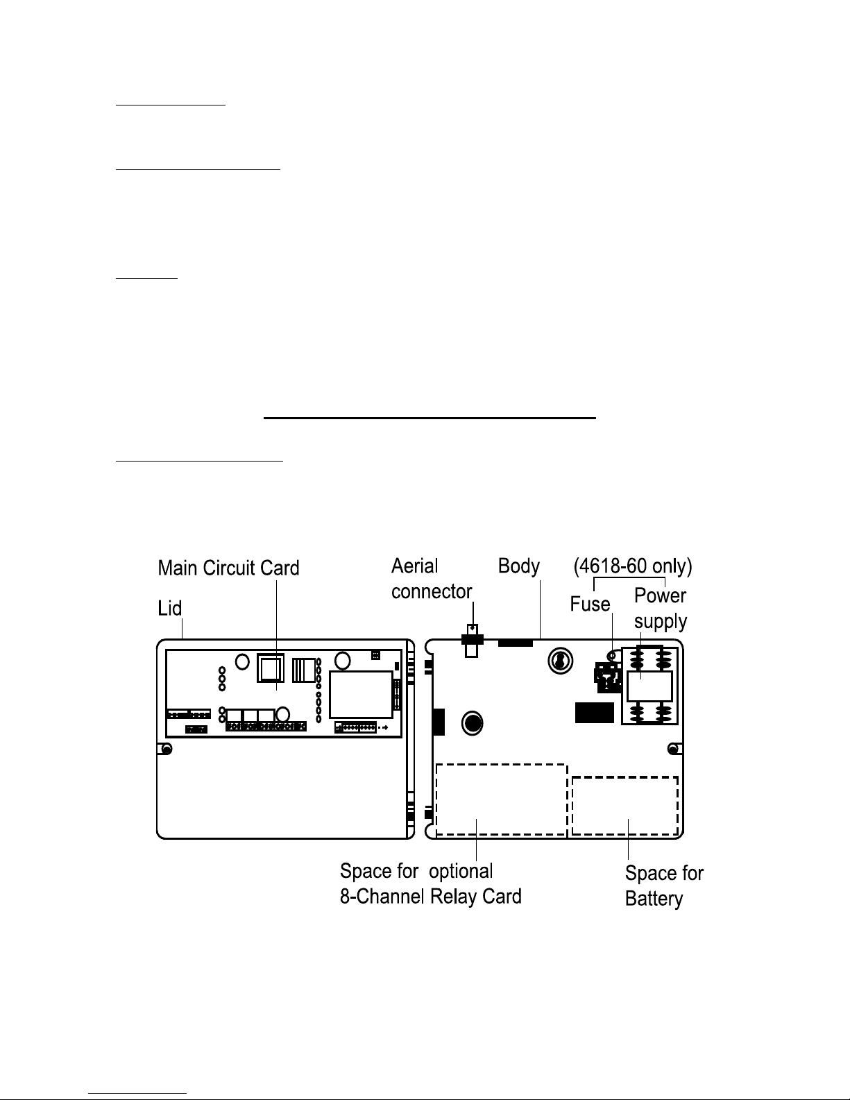
Physical Layout
The 46RX family are wall mounted units housed in a polycarbonate box
made to BS4734 requirements. Figure 1 shows the general layout of the
main components.
Figure 1. Internal Layout of 46RX Family
496371 Issue 1 3 of 20
Page 4
Technical Description 4618
The receiver and decoder circuits are on the main circuit card mounted
securely within the lid. The body of the box contains space for:
• The power supply (fitted in the 4618-60 only)
• A backup battery (not supplied)
• The 4618EUR-55, an optional 8-channel relay output card.
There differences between the three variants of the 46RX are:
• The 4618-50 power supply enclosure is empty, and there is no mains
cable terminator.
• The 4618-60 is fitted with a mains power supply, and mains cable
terminator and fuse.
• The 4619-50 has no mains power supply, and no receiver on the main
circuit board.
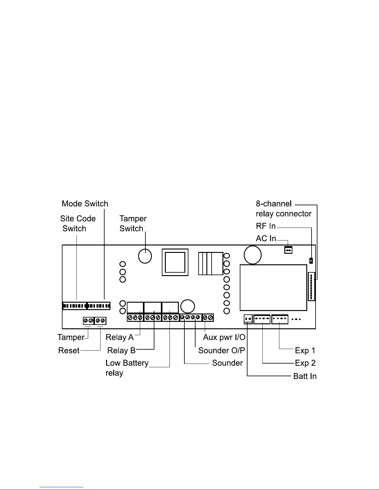
Figure 2 is an expanded view of the main circuit card showing the location of
the connectors and controls.
Figure 2. Main Circuit Card Controls And Connectors
4 of 20 496371 Issue 1
Page 5

4618 Inputs
Inputs
Radio
The 4618-50 and 4618-60 contain a standard Scantronic radio receiver which
connects to a BNC aerial socket mounted on top of the case.
Each detector sends information to the receiver using an attached radio
transmitter. The transmitter relays the information in the form of radio data
packets, using an FM signal. The signal contains a code identifying the
transmitter and information on the state of the detector. Every receiver within
range picks up the transmitter’s information, but reacts only to those transmitters it has been programmed to notice.
Mode Switches
The Mode Switches are the controls that tell the system which transmitters to
notice, and what to do with the information received. Figure 2 shows the
location of the Mode Switches on the main circuit card in the lid.
Tamper
The 46RX family contain an internally mounted tamper switch to detect
opening of the case lid (see Figure 2). The switch gives a normally closed
loop isolated from any circuits on the main circuit card. This output can be
used as required. The switch contact opens when the lid opens.
Jamming
The 46RX family can detect radio jamming if Mode Switch 3 is ON. The
cause of jamming may be interference from nearby equipment, or the receiver detecting the radio carrier continuously. See “Fault Finding” for more
information.
Reset
The 46RX family have a Reset button on the front control panel. Pressing
Reset clears all the output channels and LEDs.
If you have an expanded system with two or more members of the 46RX
family connected together, then:
• Pressing Reset on the 4618-50/60 will reset only the 4618-50/60, and
not any attached 4619-50s.
• Pressing Reset on an attached 4619-50 will reset that unit, but not any
of the other units connected to it.
Each member of the 46RX family also has a connector for an external reset
signal (see Figure 2). By applying 12VDC to the positive terminal of the reset
connector and then removing it you can reset a system of connected 46RX
family units.
496371 Issue 1 5 of 20
Page 6
Outputs 4618
Outputs
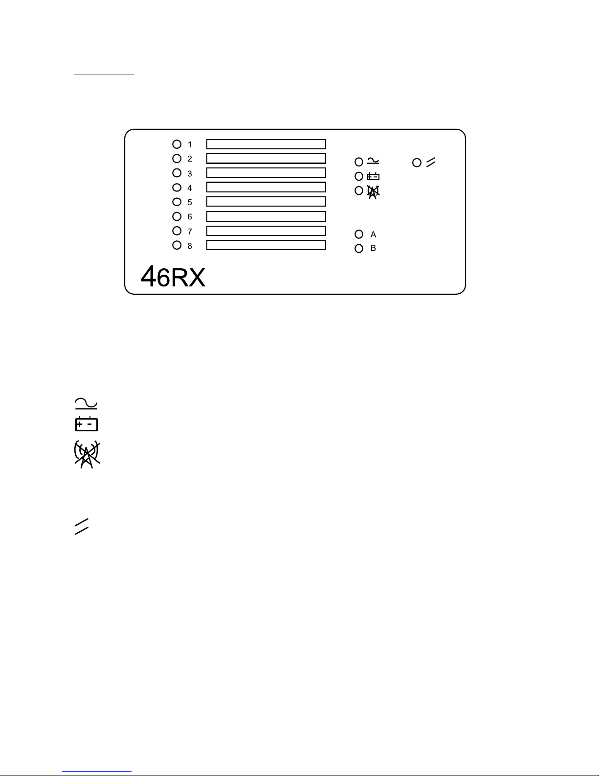
Front Panel
Each member of the 46RX family uses the display panel shown in Figure 3.
Figure 3. 46RX Family Display Panel
The vertical column of eight LEDs indicates the status of each channel
output.
The symbols on the right of the panel have the following meanings:
Power
Transmitter Low Battery
Jamming
A Common Output A
B Common Output B
Reset
Common Output Relays
Members of the 46RX family provide three output relays: Common Output
Channel A, Common Output Channel B and Low Transmitter Battery. Figure
2 shows their position and connectors.
The Normally Open, Normally Closed and Common Terminals of the relays
provide voltage free change over contacts.
The 46RX family use the Common Output Channel relays (and LEDs) to
report the status of transmitters. See Programming for more information.
The 46RX family use the Low Transmitter Battery relay to report that a
transmitter's battery is failing. See “Fault Finding” for more information.
6 of 20 496371 Issue 1
Page 7

4618 Optional 8-Channel Relay Card
Optional 8-Channel Relay Card
Each member of the 46RX family also provides eight channel outputs for
signalling the state of associated transmitters. The channel outputs can drive
a bank of eight relays, mounted on a separate circuit card in the body of the
case. Each relay provides normally open, normally closed, and common
terminals.
The relay card, part number 4618EUR-55, is optional and must be purchased
separately.
Internal Sounder
The main circuit card in the lid carries a piezo electric sounder. Its terminals
are isolated from the other circuits on the card, and are available at a connector at the bottom of the card. (See Figure 2.)
Next to the sounder terminals are the sounder output terminals. These can
be used to drive the internal sounder or an external sounder. The sounder
output comes on every time Common Output A or B comes on. See “Unit
Connection” for details of connecting the sounder output to the internal
sounder.
Expansion Units (4619-50)
If you want to receive more than eight channels from transmitters, you can
use 4619-50s as expansion units. The 4619-50 is physically similar to a
4618-50, except that it does not possess a radio receiver.
Once connected, each 4619-50 behaves like an independent unit, and can
be programmed separately from all the other units in the installation. You
should make sure that each unit has its own site code.
Connection
You may connect each member of the 46RX family to a control panel either
from the connectors on the main circuit card, or from the output connectors
on the eight-channel relay card
Figure 4 shows in detail the connectors available on the main circuit card.
Figure 4. Alarm Panel Connectors On Main Circuit Card.
496371 Issue 1 7 of 20
Page 8

External Reset Connection 4618
External Reset Connection
Figure 5. External Reset Connection.
When the user starts the control panel exit timer the Detector Reset output
removes the positive feed for six seconds. This clears the latched channels.
Connecting the Sounder
Figure 6. Sounder Connection.
Connecting the Optional 8-Channel Relay Card
Figure 7 shows the connectors available on the optional 8-channel relay card.
Figure 7. Optional 8-Channel Relay Card Connectors.
8 of 20 496371 Issue 1
Page 9

4618 Expansion Units
Expansion Units
Installation
4619-50 expansion units are supplied with an 80 cm cable to connect them to
a 4618-50 or 4618-60. Ensure that you position expansion units close
enough to the 4618-50 or 4618-60 so that the cable can connect them both.
NOTE: Do not attempt to modify the cable supplied, or use a substitute.
Connection
The recommended method of connecting 4618-50/60 and 4619 is to "daisychain" them together, as shown in Figure 8.
4618-50 4619-50 4619-50
Figure 8. Connecting Expansion Units.
You can connect the units in any order. Use Exp 1, Exp 2, or both connectors
in any unit.
PROGRAMMING
Initial Start Up
Before applying power to the system make sure all expansion units are
installed and connected.
For Systems Using a 4618-60:
NOTE: When installing the equipment for the first time at a new site, for a 4618-60
connect the mains power first and then the battery. At subsequent maintenance, or re-installations at existing sites, connect the battery first and then the
supply. The instructions below assume that you are installing the equipment at
a new site.
1. For ALL units in the system set Mode Switch 2 (Power Mode) ON:
on
1 2 3 4 5 6 7 8
2. Make sure the power lead from the transformer is plugged into the 4618
AC Power Input connector on the circuit card.
3. Wire in the mains power supply from a non-switched, fused (1A rating),
spur point.
496371 Issue 1 9 of 20
Page 10

Setting Up Receivers and Transmitters 4618
You should see the Power LED glow. If the sounder is connected you
should hear a short tone.
For Systems Containing a 4618-50
1. For ALL units in the system set Mode Switch 2 (Power Mode)
on
to OFF:
1 2 3 4 5 6 7 8
2. Connect the external 12V supply.
You should see the Power LED glow. If the sounder is connected you
should hear a short tone.
To Connect a Backup Battery
1. Connect the battery lead spade connectors to the battery terminals
(observing polarity)
2. Connect battery lead connector to the Batt. In/Out connector on the
main circuit card.
Note: If the sounder gives a continuous tone when you apply power then the mode
switches are set to an unacceptable mode number. The 8-channel LEDs will
also show a running pattern of flashes. Set the Mode Switches to the required
mode for your application.
Setting Up Receiver And Transmitters
To make the 46RX family operate correctly you must set two groups of
switches:
1. The site code switch on both the transmitters and the 46RX family
receiver to the same pattern.
2. The mode switch on the 46RX family receiver to the correct mode.
Figure 4 shows the switches in more detail.
Figure 9. Site Switch and Mode Switch
10 of 20 496371 Issue 1
Page 11

4618 Site Codes
Site Codes
You must set the 46RX family receiver and the transmitters to the same site
code. The 46RX family receiver will only respond to signals from a transmitter
set to the correct site code.
For some modes the site code to set for the transmitters is shorter than the
site code set on the 46RX family receiver. The Mode Details section gives
the correct number of switches to set on the transmitter.
Mode Switch
To set the 46RX family receiver into the desired mode, set switches 4 to 8 of
the Mode Switch into the correct pattern. The pattern for each mode is shown
in the Mode Details section of this Chapter. Note that switch 1 (Self Test)
should always be OFF.
Transmitters and Trigger Devices
This sub-section describes how individual transmitters signal the state of their
trigger devices. Consult the instructions provided with each transmitter for
more details on installing and using the transmitters.
Each type of transmitter uses one or more channels to send information to
the receiver. For example, a personal attack button might use one channel,
but a door contact sensor might use two: one for door open/closed and one
for tamper reporting.
For two channel transmitters this guide calls the channel normally used for
alarm reporting "channel A", and the channel used for tamper reporting
"channel B". Single channel transmitters have the equivalent of channel A
only.
Four channel transmitters have the equivalent of A, B, C, and D channels.
Transmitters send one of two signals over individual channels: ACTIVE or
RESTORE. Some transmitters send an ACTIVE signal every time the detector is activated (for example a pendant panic button). Other transmitters send
an ACTIVE signal when the detector is activated in one direction, and a
RESTORE signal when the detector is activated in the other direction (for
example a door contact).
To make sure the 46RX family receiver indicates correctly which transmitter
has signalled, you must set the appropriate switches within the transmitter to
a channel or device number. The Mode Details section tells you which
switches to set in the transmitter to obtain the correct device numbers. Ignore
the switch settings suggested in the leaflets supplied with the transmitters
(which are for use with other receivers). Use the switch settings suggested in
this Guide.
496371 Issue 1 11 of 20
Page 12

Allocating Transmitters to Modes 4618
Allocating Transmitters to Modes
The 46RX family receivers provide a total of 22 different modes. Mode 22 is
used to show the message quality of transmitters. Modes 1 to 21 provide
different ways of allocating transmitter channels to receiver output channels.
Each mode is designed for a different variety of one, two or four channel
transmitters.
In order to help you with an initial choice of Mode, Figure 10 below shows the
recommended modes for the different types of transmitter mentioned above.
NOTE: Other combinations of transmitter and mode may appear to work, but
Scantronic will not accept responsibility for equipment used in this manner, or
any consequent loss.
FOREBMUN
SLENNAHC
SEDOM8-191,31-951,4181-6112-02
ROTCETED
2064/1064
*3064
4064
5064
6064
8064
9064
REPIV
4264
ENOOWTRUOFOWTPUORG
yy yyy
yy y y y
yyy
yyy
yyy
yyy
yyyyy
yyy
.noitatnemucod3064otrefeR*
Figure 10. Transmitters and Modes.
Receiver Output Channel Types
y
By choosing the appropriate mode you can set up output channels on the
46RX family receiver to respond in one of four different ways:
Latching The receiver switches the channel ON when it
Momentary The receiver switches a channel ON when it
12 of 20 496371 Issue 1
receives an ACTIVE signal from a transmitter, and
OFF when it receives a RESTORE signal.
receives an ACTIVE signal, and then OFF after
four seconds (approximately). The receiver ignores
RESTORE signals for momentary channels.
Page 13

4618 Common Output Channels
Manual Reset The receiver switches a channel ON when it
receives an ACTIVE signal. You must RESET the
receiver to switch the channel OFF. Note that this
will also switch all other channels to OFF.
Toggle The receiver switches a channel ON when it
receives an ACTIVE signal, and then switches the
channel OFF when it receives the next ACTIVE
signal.
Common Output Channels
While in single channel mode (1 to 8) the receiver turns common output A
ON whenever one of the eight channel outputs is ON.
In dual channel mode (9 to 13 and 16 to 19) the receiver turns common
output A ON whenever it receives an ACTIVE signal on channel A from a
transmitter. The receiver turns common output B ON whenever it receives an
ACTIVE signal on channel B from a transmitter.
Mode Details - Modes 1 To 8
Transmitter Set-up
For modes 1 to 8, at the transmitter:
• Set switches 1 to 8 to the site code
• Set the last four switches as follows:
1 2 3 4 CHANNEL NO
SWITCHES
9, 10, 11, 12
5 6 7 8
MODE SW SETTING
on
1 1-8 Short Momentary
1 2 3 4 5 6 7 8
on
2 1-8 Latching
1 2 3 4 5 6 7 8
on
3 1-6 Latching, 7 & 8 Momentary
1 2 3 4 5 6 7 8
on
4 1-4 Latching, 5-8 Momentary
1 2 3 4 5 6 7 8
on
off
on
off
496371 Issue 1 13 of 20
Page 14

Modes 9 to 13, and 19 4618
on
5 1 & 2 Latching, 3-8 Momentary
1 2 3 4 5 6 7 8
on
6 1-8 Momentary
1 2 3 4 5 6 7 8
on
7 1-8 Latch ON, Manual Clear
1 2 3 4 5 6 7 8
on
8 1-8 Toggle
1 2 3 4 5 6 7 8
Modes 9 To 13, and 19 - Transmitter Switch Settings
At the transmitter:
• Set switches 1 to 8 to the site code
• Set switches 9 and 10 to a device number in the range 1 to 4 as
follows:
The receiver allocates two channels to each device (for example channel 1
and 2 to device 1, channel 3 and 4 to device 2). Odd numbered channels
correspond to channel A from the transmitter. Even numbered channels
correspond to channel B from the transmitter.
MODE SW SETTING
on
9 1,3,5,7 Momentary, 2,4,6,8 Latching
1 2 3 4 5 6 7 8
on
10 3,5,7 Momentary, 1,2,4,6,8 Latching
1 2 3 4 5 6 7 8
on
11 5,7 Momentary, 1,2,3,4,6,8 Latching
1 2 3 4 5 6 7 8
on
12 7 Momentary, 1-6, & 8 Latched
1 2 3 4 5 6 7 8
on
13 1-8 Latching
1 2 3 4 5 6 7 8
on
19 1-8 Momentary
1 2 3 4 5 6 7 8
14 of 20 496371 Issue 1
Page 15

4618 Modes 14 and 15
Modes 14 And 15 - Transmitter Switch Settings
At the transmitter:
• Set switches 1 to 7 to the site code
• Set switch 8 ON for device 1 or OFF for device 2.
The receiver allocates four channels to each device. Channels 1 to 4 belong
to device 1, channels 5 to 8 belong to device 2.
MODE SW SETTING
on
14 All Latching (2x4 Channels)
1 2 3 4 5 6 7 8
on
15 1,3,5,7 Momentary 2,4,6,8 Latching
1 2 3 4 5 6 7 8
Modes 16 To 18 - Transmitter Switch Settings
At the transmitter:
• Set switches 1 to 7 to the site code
• Set switches 8, 9, and 10 to the channel number as follows:
The receiver allocates one channel to each device.
The receiver activates Common Output A (and the appropriate output chan-
nel) whenever any transmitter sends an ACTIVE signal on its channel A.
The receiver allocates common output B to the channel B signals of all eight
transmitters. If the receiver receives ACTIVE signals on channel B from any
transmitter then it turns relay B ON. The receiver will only turn relay B OFF
when all eight transmitters have sent RESTORE on their B channels.
MODE SW SETTING
16 1-4 Latching, 5-8 Mmt'y (Common B)
17 1-4 Latching, 5-8 Mmt'y (A or B)
18 All Latching, Manual Clear
on
1 2 3 4 5 6 7 8
on
1 2 3 4 5 6 7 8
on
1 2 3 4 5 6 7 8
496371 Issue 1 15 of 20
Page 16

4618
Mode 20 and 21 (Group Modes)
Modes 20 and 21 are used for special applications where a transmitter must
activate more than one receiver. Refer to the Installation Guide supplied with
the unit for detailed examples.
MODE SW SETTING
on
20 8 Transmitter Group
1 2 3 4 5 6 7 8
on
21 16 Transmitter Group
1 2 3 4 5 6 7 8
TESTING
Sensor/Transmitter Tests
After completing the initial installation, check that the unit is receiving signals
from all the transmitters allocated to it. Carry out the following steps for all
transmitters:
1. Activate the transmitter and check that the correct channel LEDs light.
2. Check that the channel LEDs go out after 4 secs for momentary chan-
nels.
3. Check that the channel LEDs go out on a RESTORE signal for latched
channels.
4. Activate the tamper on a transmitter, check that the correct channel
LED lights.
5. Restore the tamper and check that the correct channel LED goes out.
6. If you have set the unit to Modes 7 or 18 check that the reset button
works.
Other Checks
Check that the tamper switch on the case is wired and operates as intended.
Check that the sounder is wired and working as intended.
If you have installed an external reset connection then check that it works. All
units should reset when the external reset operates.
Mode 22 Message Quality Test
Your installation may be giving problems by not reporting the activation of a
transmitter reliably. Poor reception at the receiver is one possible cause.
Mode 22 Message Quality provides a way of checking the reception quality
from any transmitter.
16 of 20 496371 Issue 1
Page 17

4618 Fault Finding
on
1. Set Mode Switches 4 to 8 as follows:
1 2 3 4 5 6 7 8
2. Activate a transmitter
Channel 1 and the jamming LED flash for the duration of the transmis-
sion.
The LEDs stop flashing, leaving one channel LED glowing steadily.
3. Repeat step 2 several times (four or five) until you obtain consistent
results.
The number of the channel LED that glows steadily at the end of each test
shows the quality of the signal. Channel 1 LED (or no LED lit) indicates a very
poor signal. Channel 8 LED indicates a very good signal.
If any transmitter gives a reading of 3 or less then the quality is not good
enough for reliable reception.
Notes:
1) Ignore any indications on Common Outputs A and B during the test.
2) The unit flashes the Jamming LED on its own if it detects transmissions from a device using an incorrect site code.
FAULT FINDING
The next page shows fault indications on the control panel. In the diagram
means a LED glows steadily, while means a LED flashes. The subse-
quent page shows other fault indications.
496371 Issue 1 17 of 20
Page 18

4618
18 of 20 496371 Issue 1
Page 19

4618 Fault Finding
NOITACIDNIESUACELBISSOPNOITCA
.purewopt’nseoDesufrewopCA
.)06-8164(esufegnahC
.nwolb
tonelbacnICA
.)06-8164(snoitcennockcehC
detcennoc
tonelbacV21CD
)05-8164(ylppusCDkcehC
)05-8164(detcennoc
norednuoS
.ylsuounitnoc
tonDELlennahC
.gnithgil
edomdilavnI
.sehctiwsedomkcehC
detceles
/rettimsnarT
.edocetisemasotreviecerdnarettimsnartteS
ottesrevieceR
.edocetisgnorw
tonyalerlennahC
lennahC(gnikrow
tondraobyaleR
.detcennoc
.ylreporpdetcennocsidraob
niamotdracyalermorfelbacnobbirtahtkcehC
.)KOsDEL
lennahctcerrocnI
.gnikrowDEL
edomgnorW
.edomtcerroctceleS
.detceles
ottesrettimsnarT
.lennahctcerrocotrettimsnartteS
.lennahcgnorw
tonyalerlennahC
gnitteser
edomgnorW
.edomtcerroctceleS
.detceles
rettimsnarttcerrocnI
.epytrettimsnartegnahC
.nesohcepyt
.gnikrowton05-9164/revieceR
.edocetisemasotreviecerdnarettimsnartteS
ottessrettimsnart
.edocetisgnorw
.detcennoctonelbaC.yltcerrocdetcennocsielbactahtkcehC
rewoptneiciffusnI
.elbaliava
tuptuoyraillixuaoN
.rewop
rewophcumooT
hctiwsylop,niard
.teser
.06/05-8164
reps05-9164rewefroeerhteraerehterusnE
othctiwsyloproftiaW.dnamedrewopesaerceD
.detarepo
tontuptuorednuoS
gnikrow
rewophcumooT
hctiwsylop,niard
.teser
othctiwsyloproftiaW.dnamedrewopesaerceD
.detarepo
.gnikrowtonrednuoStonrednuoS
.rednuosotsnoitcennockcehC
.yltcerrocdetcennoc
.gnikrowtonyrettaBtonyrettaB
gnigrahcer
.noitallatsni
repseirettabhA2.1rewefroruoferaerehterusnE
.deliafyrettaB.yrettabegnahC
tonteserlanretxE
gnikrow
deilppateseR
.yltcerrocdeilppadnadetcennoctesertahtkcehC
.yltcerrocni
496371 Issue 1 19 of 20
Page 20

4618
20 of 20 496371 Issue 1
 Loading...