

Page 1

EkaNet™ Har dwar e Manual
Document Number
10156
Revision 07
Eka Systems, Inc.
20251 Century Boulevard, Suite 120
Germantown, MD 20874
Tel (301) 990-3450
Fax (301) 990-3451
Page 2

EKA CONFIDENTIAL
Confidential and Proprietary
Reproduction or Distribution Prohibited
This document is for informational purposes only. It contains
information that is confidential and proprietary. This document
has been prepared by and is the property of Eka Systems, Inc.
By accepting and reviewing this document, you agree that you
will treat its contents as confidential and proprietary, and that
you will not copy, distribute or otherwise disclose the information
contained herein to third parties.
Page 3

Table of Contents
Table of Contents
1. Introduction . . . . . . . . . . . . . . . . . . . . . . . . . . . . . . . . . . . . . . . . . . . . . . . . . . . . 1 - 1
1.1 Overview . . . . . . . . . . . . . . . . . . . . . . . . . . . . . . . . . . . . . . . . . . . . . . . . . . . . . . 1 - 1
1.1.1 Product Highlights . . . . . . . . . . . . . . . . . . . . . . . . . . . . . . . . . . . . . . . . . 1 - 1
1.2 Supporting Documents . . . . . . . . . . . . . . . . . . . . . . . . . . . . . . . . . . . . . . . . . . . . 1 - 2
1.3 Version History . . . . . . . . . . . . . . . . . . . . . . . . . . . . . . . . . . . . . . . . . . . . . . . . . . 1 - 2
2. ECR-2400 Node Hardware. . . . . . . . . . . . . . . . . . . . . . . . . . . . . . . . . . . . . . . . . 2 - 1
2.1 Overview . . . . . . . . . . . . . . . . . . . . . . . . . . . . . . . . . . . . . . . . . . . . . . . . . . . . . . 2 - 3
2.1.1 ECR-2400 Node Features . . . . . . . . . . . . . . . . . . . . . . . . . . . . . . . . . . . 2 - 3
2.1.2 ECR-2400 Node Layout . . . . . . . . . . . . . . . . . . . . . . . . . . . . . . . . . . . . 2 - 4
2.2 Installation and Operation . . . . . . . . . . . . . . . . . . . . . . . . . . . . . . . . . . . . . . . . . 2 - 5
2.2.1 What the Blinking Lights Mean . . . . . . . . . . . . . . . . . . . . . . . . . . . . . . . 2 - 5
2.2.1.1 The Green LED. . . . . . . . . . . . . . . . . . . . . . . . . . . . . . . . . . . . . 2 - 5
2.2.1.2 The Red LED . . . . . . . . . . . . . . . . . . . . . . . . . . . . . . . . . . . . . . 2 - 5
2.3 ECR-2400 Node Specifications . . . . . . . . . . . . . . . . . . . . . . . . . . . . . . . . . . . . . 2 - 6
3. Elster A3/Alpha Plus Node Hardware. . . . . . . . . . . . . . . . . . . . . . . . . . . . . . . . 3 - 1
3.1 Overview . . . . . . . . . . . . . . . . . . . . . . . . . . . . . . . . . . . . . . . . . . . . . . . . . . . . . . 3 - 3
3.1.1 Elster A3/Alpha Plus Node Features . . . . . . . . . . . . . . . . . . . . . . . . . . . 3 - 4
3.1.2 Elster A3/Alpha Plus Node Layout . . . . . . . . . . . . . . . . . . . . . . . . . . . . 3 - 4
3.2 Installation and Operation . . . . . . . . . . . . . . . . . . . . . . . . . . . . . . . . . . . . . . . . . 3 - 5
3.2.1 What the Blinking Lights Mean . . . . . . . . . . . . . . . . . . . . . . . . . . . . . . . 3 - 6
3.2.1.1 The Green LED. . . . . . . . . . . . . . . . . . . . . . . . . . . . . . . . . . . . . 3 - 6
3.2.1.2 The Red LED . . . . . . . . . . . . . . . . . . . . . . . . . . . . . . . . . . . . . . 3 - 6
3.3 Elster A3/Alpha Plus Node Specifications . . . . . . . . . . . . . . . . . . . . . . . . . . . . . 3 - 7
4. RESI-MON Node Hardware . . . . . . . . . . . . . . . . . . . . . . . . . . . . . . . . . . . . . . . . 4 - 1
4.1 Overview . . . . . . . . . . . . . . . . . . . . . . . . . . . . . . . . . . . . . . . . . . . . . . . . . . . . . . 4 - 2
4.1.1 RESI-MON Node Features . . . . . . . . . . . . . . . . . . . . . . . . . . . . . . . . . . 4 - 2
4.1.2 RESI-MON Node Layout . . . . . . . . . . . . . . . . . . . . . . . . . . . . . . . . . . . . 4 - 3
4.2 Installation and Operation . . . . . . . . . . . . . . . . . . . . . . . . . . . . . . . . . . . . . . . . . 4 - 4
4.2.1 What the Blinking Lights Mean . . . . . . . . . . . . . . . . . . . . . . . . . . . . . . . 4 - 4
4.2.1.1 The Green LED. . . . . . . . . . . . . . . . . . . . . . . . . . . . . . . . . . . . . 4 - 4
4.2.1.2 The Red LED . . . . . . . . . . . . . . . . . . . . . . . . . . . . . . . . . . . . . . 4 - 4
4.3 RESI-MON Node Specifications . . . . . . . . . . . . . . . . . . . . . . . . . . . . . . . . . . . . 4 - 5
5. EkaNet Pulse Node Hardware. . . . . . . . . . . . . . . . . . . . . . . . . . . . . . . . . . . . . . 5 - 1
5.1 Overview . . . . . . . . . . . . . . . . . . . . . . . . . . . . . . . . . . . . . . . . . . . . . . . . . . . . . . 5 - 2
5.1.1 EkaNet Pulse Node Features . . . . . . . . . . . . . . . . . . . . . . . . . . . . . . . . 5 - 2
EkaNet Hardware Manual 10156-07
Eka Proprietary and Confidential
Page 4

Table of Contents
5.2 EkaNet Indoor Pulse Nodes . . . . . . . . . . . . . . . . . . . . . . . . . . . . . . . . . . . . . . . . 5 - 3
5.2.1 Layout . . . . . . . . . . . . . . . . . . . . . . . . . . . . . . . . . . . . . . . . . . . . . . . . . . 5 - 3
5.2.2 Connection and Operation . . . . . . . . . . . . . . . . . . . . . . . . . . . . . . . . . . . 5 - 4
5.3 EkaNet Outdoor Pulse Nodes . . . . . . . . . . . . . . . . . . . . . . . . . . . . . . . . . . . . . . 5 - 5
5.3.1 Layout . . . . . . . . . . . . . . . . . . . . . . . . . . . . . . . . . . . . . . . . . . . . . . . . . . 5 - 5
5.3.2 Connection and Operation . . . . . . . . . . . . . . . . . . . . . . . . . . . . . . . . . . . 5 - 6
5.4 What the Blinking Lights Mean . . . . . . . . . . . . . . . . . . . . . . . . . . . . . . . . . . . . . . 5 - 7
5.4.1 The Green LED . . . . . . . . . . . . . . . . . . . . . . . . . . . . . . . . . . . . . . . . . . . 5 - 7
5.4.2 The Red LED . . . . . . . . . . . . . . . . . . . . . . . . . . . . . . . . . . . . . . . . . . . . . 5 - 7
5.5 EkaNet Pulse Node Specifications . . . . . . . . . . . . . . . . . . . . . . . . . . . . . . . . . . . 5 - 8
6. Gateway Hardware. . . . . . . . . . . . . . . . . . . . . . . . . . . . . . . . . . . . . . . . . . . . . . . 6 - 1
6.1 Overview . . . . . . . . . . . . . . . . . . . . . . . . . . . . . . . . . . . . . . . . . . . . . . . . . . . . . . . 6 - 1
6.1.1 EkaNet Gateway Features . . . . . . . . . . . . . . . . . . . . . . . . . . . . . . . . . . . 6 - 1
6.2 Configuring the Gateway Using the Field Tool . . . . . . . . . . . . . . . . . . . . . . . . . . 6 - 1
6.2.1 IP Config Settings . . . . . . . . . . . . . . . . . . . . . . . . . . . . . . . . . . . . . . . . . 6 - 2
6.2.2 User Config Settings . . . . . . . . . . . . . . . . . . . . . . . . . . . . . . . . . . . . . . . 6 - 3
6.2.3 NTP Config Settings . . . . . . . . . . . . . . . . . . . . . . . . . . . . . . . . . . . . . . . 6 - 5
6.3 The Compact Flash Card . . . . . . . . . . . . . . . . . . . . . . . . . . . . . . . . . . . . . . . . . . 6 - 5
6.4 Installing an Indoor Gateway . . . . . . . . . . . . . . . . . . . . . . . . . . . . . . . . . . . . . . . 6 - 6
6.5 Installing an Outdoor Gateway . . . . . . . . . . . . . . . . . . . . . . . . . . . . . . . . . . . . . . 6 - 8
6.6 Verifying Gateway Connectivity . . . . . . . . . . . . . . . . . . . . . . . . . . . . . . . . . . . . . 6 - 11
6.7 Gateway Specifications . . . . . . . . . . . . . . . . . . . . . . . . . . . . . . . . . . . . . . . . . . . 6 - 12
10156-07 EkaNet Hardware Manual
Eka Proprietary and Confidential
Page 5

List of Figures
Figure 1.1: The Architecture of the EkaNet Wireless Mesh Network System ............ 1 - 1
Figure 2.1: ECR-2400 Node .......................................................................................2 - 3
Figure 2.2: ECR-2400 Node Layout ........................................................................... 2 - 4
Figure 2.3: Eka Node Placement within a ECR-2400 Meter ...................................... 2 - 5
Figure 3.1: Elster A3/Alpha Plus Node - Top View .................................................... 3 - 3
Figure 3.2: Elster A3/Alpha Plus Node - Side View ................................................... 3 - 3
Figure 3.3: Elster A3/Alpha Plus Node Layout ........................................................... 3 - 4
Figure 3.4: Eka Node Placement within an Alpha Meter ............................................ 3 - 5
Figure 4.1: RESI-MON Node ..................................................................................... 4 - 2
Figure 4.2: RESI-MON Node Layout .......................................................................... 4 - 3
Figure 5.1: Layout of EkaNet Pulse Node for Indoor Installations ............................. 5 - 3
Figure 5.2: EkaNet Indoor Wireless Pulse Node - Cover Removed .......................... 5 - 4
Figure 5.3: Layout of EkaNet Pulse Node for Outdoor Installations ...........................5 - 5
Figure 5.4: EkaNet Outdoor Wireless Pulse Node - Cover Removed ........................ 5 - 6
Figure 6.1: Gateway Maintenance IP Configuration .................................................. 6 - 2
Figure 6.2: Gateway Maintenance User Configuration .............................................. 6 - 3
Figure 6.3: Successful Update to User Information ................................................... 6 - 4
Figure 6.4: Gateway Maintenance NTP Configuration ............................................... 6 - 5
Figure 6.5: Indoor Gateway ........................................................................................ 6 - 6
Figure 6.6: Indoor Gateway - Power Connection ....................................................... 6 - 7
Figure 6.7: Indoor Gateway - Cover Removed .......................................................... 6 - 7
Figure 6.8: Weather Proof Outdoor EkaNet Gateway - Closed ................................. 6 - 8
Figure 6.9: Weather-Proof Outdoor Gateway - Latches ............................................. 6 - 9
Figure 6.10: Internal Components of an Outdoor Gateway ....................................... 6 - 10
Figure 6.11: Power Input Terminals on an Outdoor Gateway .................................... 6 - 11
List of Figures
EkaNet Hardware Manual 10156-07
Eka Proprietary and Confidential
Page 6
1. Introduction
1.1 Overview
1.1.1 Product Highlights
EkaNet™ Har dwar e Manual
This document describes the node and gateway hardware
components of an EkaNet wireless mesh network
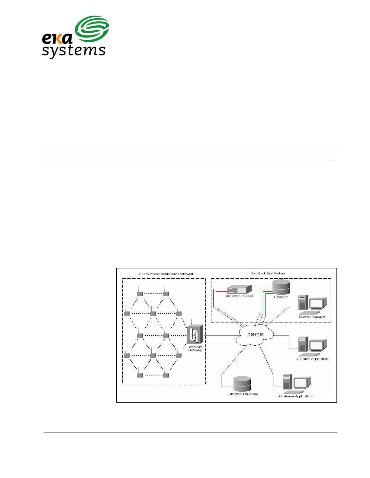
EkaNet’s wireless mesh network consists of multiple nodes communicating via
a gateway with a server through either an IP connection or phone modem. In
this self-configuring, peer-to-peer, multi-hop network, data is intelligently routed
between nodes and gateways in the most efficient manner. Figure 1.1 shows
the components of an EkaNet wireless mesh network including those supplied
by the customer. This do cument describes the node and gateway hardwar e that
make up the EkaNet wireless mesh network.
Figure 1.1 The Architecture of the EkaNet Wireless Mesh Network System
10156-07 1 - 1 EkaNet Hardware Manual
Eka Proprietary and Confidential
Page 7
Introduction
1.2 Supporting Documents
The following documents contain supporting details on the operation of your
EkaNet wireless mesh network:
1.3 Version History
• EkaNet System Description — describes the system features of
EkaNet’s wireless mesh network for embedded device networking
applications
• EkaNet Operations Manual — describes the procedures to plan,
deploy, and maintain your EkaNet wireless mesh network
• EkaNet Field Tool User Manual — describes the features and use of
the EkaNet Field tools
• Network Manager User Guide — describes the use of the Network
Manager software. Includes sizing, installation, and administration
information.
Revision
Number
01 September 2005 Initial Version - 10156
02 March 2006 Added RESI-MON Node (See “RESI-MON
03 May 2006 Updated Gateway section with instructions on
04 July 2006 Updated Radio Specifications (See “Radio
05 August 2006
Date Released Comment
Node Hardware” on page 4 - 1), Elster Node
(See “Elster A3/Alpha Plus Node Hardware” on
page 3 - 1) sections.
gateway configuration (See “Configuring the
Gateway Using the Field Tool” on page 6 - 1).
Specifications” on page 2-6.) Add ed FCC
Warning (See “Warning” on page 4-1.)
• Updated Radio Specifications for ECR-2400
Node Hardware (See “Radio Specifications”
on page 2-6.)
• Updated Radio Specifications for Elster A3/
Alpha Plus Node Hardware (See “Radio
Specifications” on page 3-7.)
• Updated Radio Specifications for RESI-MON
Hardware (See “Radio Specifications” on
page 4-5.)
06 October 2006
07 January 2007
• Added EkaNet Pulse Node section (See
“EkaNet Pulse Node Hardware” on page 5-1.)
• Added instructions on RF exposure
compliance
EkaNet Hardware Manual 1 - 2 10156-07
Eka Proprietary and Confidential
Page 8

Introduction
This document was prepared by:
Eka Systems, Inc.
Germantown, MD
© Eka Systems, Inc., 2006
10156-07 1 - 3 EkaNet Hardware Manual
Eka Proprietary and Confidential
Page 9
ECR-2400 Node Hardware
2. ECR-2400 Node Hardware
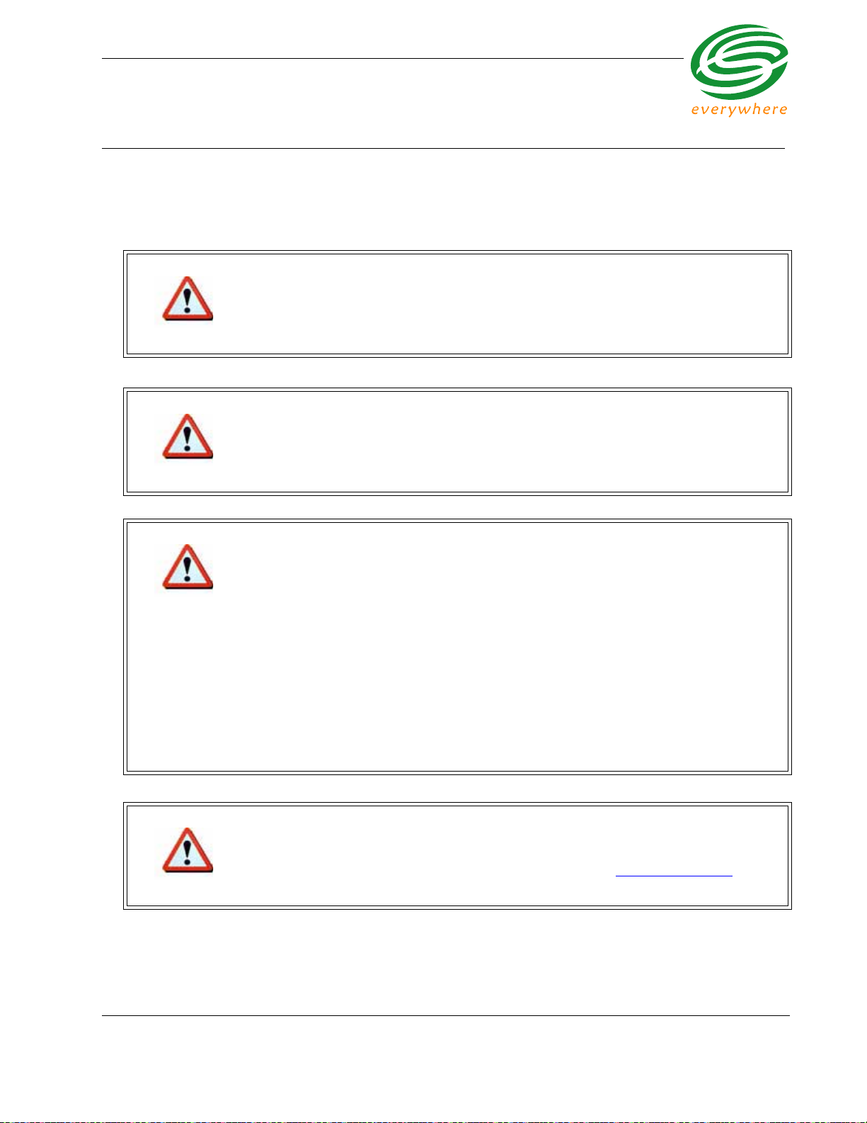
FCC Notice
Changes or modifications not expressly approved by the party responsible for compliance could void the user’s
authority to operate the equipment.
The Original Equipment Manufacturer (OEM) must ensure that FCC Labeling requirements are
met. This includes a clearly visible label on the outside of the OEM enclosure specifying the
appropriate EKA Systems FCC identifier for this product as well as the FCC Notice below.
Warning
This device complies with Part 15 of the FCC Rules. Operation is subject to the following two
conditions:
(1) This device may not cause harmful interference, and
(2) This device must accept any interference received, including interference that may cause
Warning
undesired operation.
Warning
This equipment has been tested and found to comply with the limits for a Class B digital device,
pursuant to part 15 of the FCC Rules. These limits are designed to provide reasonable
protection against harmful interference in a residential installation. This equipment generates,
uses and can radiate radio frequency energy and, if not installed and used in accordance with
the instructions, may cause harmful interference to radio communications. However, there is no
guarantee that interference will not occur in a particular installation.
If this equipment does cause harmful interference to radio or television reception, which can be
determined by turning the equipment off and on, the user is encouraged to try to correct the
interference by one or more of the following measures:
• Reorient or relocate the receiving antenna.
• Increase the separation between the equipment and receiver.
• Connect the equipment into an outlet on a circuit different from that to which the receiver is
connected.
• Consult the dealer or an experienced radio/TV technician for help.
EkaNet Hardware Manual 2 - 1 10156-07
Eka Proprietary and Confidential
Page 10

ECR-2400 Node Hardware
To comply with FCC RF exposure compliance requirements, the antenna used for this
transmitter must be installed to provide a separation distance of at least 20 cm from all persons
and must not be co-located or operate in conjunction with any other antenna or transmitter.”
As such, the radio component of this device is intended only for OEM integrators under the
following two conditions:
Warning
1. The antenna must be installed such that 20 cm is maintained between the antenna and
2. The transmitter module may not be co-located with any other transmitter or antenna.
As long as the two conditions above are met, further transmitter testing will not be required.
However, the OEM integrator is still responsible for testing their end product for any additional
compliance requirements required with this module installed (e.g., digital device emissions, PC
peripheral requirements).
In the event that these conditions cannot be met (for example, co-location with another
transmitter), then the FCC authorization is no longer considered valid and the FCC ID cannot
be used on the final product. In these circumstances, the OEM integrator will be responsible for
re-evaluating the end product (including the transmitter) and obtaining a separate FCC
authorization.
End Product Labeling
This transmitter module is authorized only for use in devices where the antenna may be
installed such that 20 cm may be maintained between the antenna and users (for example
access points, routers, wireless ASDL modems, certain laptop configurations, and similar
equipment). The final end product must be labeled in a visible area with the following:
“FCC ID: F9X2400B”.
users
The radio component is an integral part of the Eka module and cannot be removed.
10156-07 2 - 2 EkaNet Hardware Manual
Eka Proprietary and Confidential
Page 11
ECR-2400 Node Hardware
2.1 Overview
The ECR-2400 node is an under-the-glass board designed for installation in an
ECR-2400 meter. The node plugs into the meter and provides an easy and
reliable way to enable meters to automatically form a wireless mesh network.
This section describes the procedures to integrate an ECR-2400 node with a
ECR-2400 meter.
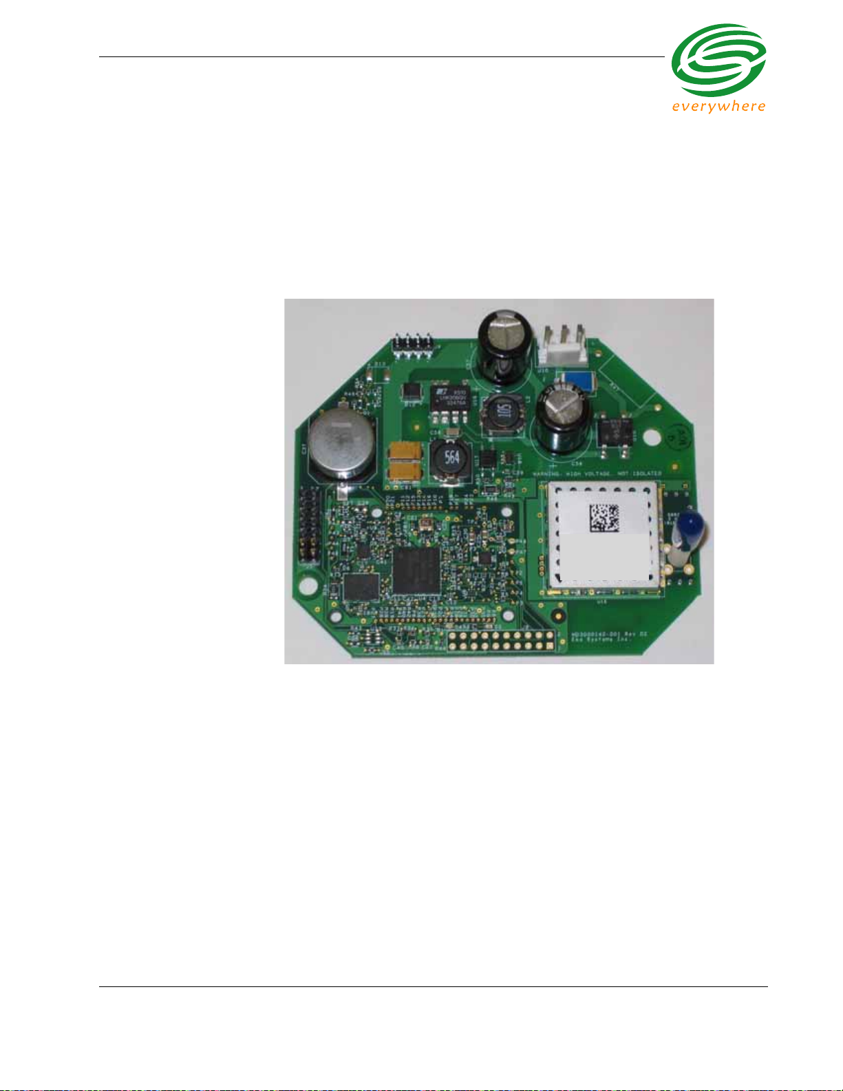
2.1.1 ECR-2400 Node Features
ECR-2400 nodes:
00140800001C
1400000018
FCC ID P9X2400b
Figure 2.1 ECR-2400 Node
• operate in the 2.4 GHz band
• fit “under the glass”
• performs automatic time synchronization
• provide real-time access to interval data
• contain local non-volatile data storage
• provide full wireless routing capability
EkaNet Hardware Manual 2 - 3 10156-07
Eka Proprietary and Confidential
Page 12
ECR-2400 Node Hardware
2.1.2 ECR-2400 Node Layout
Figure 2.2 below is a simple diagram of an ECR-2400 node. The primary
components of the node are:
• the meter interface connector - connects the node to the meter
• the AC power connection - supplies power to the node
• the node’s serial number - the node’s unique identifier
• LEDs - red and green lights displaying node’s operating status
Meter Interface
Connector
LED S tatus Light s
AC Power
Connector
00140800001C
1400000018
FCC ID P9X2400b
Bar C ode and l abel
cont ai n t he node’ s
radio address and
serial num ber .
These num bers are
also em bedded i n
the node’s software .
Antenna
Figure 2.2 ECR-2400 Node Layout
Each ECR-2400 node is uniquely identified with a serial number . This number is
displayed on the label and is contained on the bar code. In addition, the number
is also embedded in the node’s software. This serial number is the number
displayed on the Field Tool and Network Manager to identify the node.
During installation, it is important to note the Eka Serial Number and the serial
number of the meter in which it is installed in the event that the node and/or
meter require troubleshooting.
10156-07 2 - 4 EkaNet Hardware Manual
Eka Proprietary and Confidential
Page 13
ECR-2400 Node Hardware
2.2 Installation and Operation
Install the ECR-2400 node in the ECR-2400 meter as shown in Figure 2.3.
Front Face Plate
EC R-2400 Meter Board
EC R-2400 N ode
Antenna
AC Power
Connector
LED Stat us Light s
Meter Interface
Connector
Figure 2.3 Eka Node Placement within a ECR-2400 Meter
1. Connect the ECR-2400 Meter Board to the Meter Interface Connector on
the ECR-2400 Node.
2. Connect the AC power connector on the ECR-2400 node to the line and
neutral connectors on the base of the ECR-2400 meter.
As soon as the meter is installed and powered on, the ECR-2400 node will
begin operation.
2.2.1 What the Blinking Lights Mean
2.2.1.1 The Green LED
During the initial boot up the green LED may blink unevenly. However after 10
seconds the green LED should begin blinking at a steady r ate of 1/2 second on
and 1/2 second off. This is considered the node’s “heartbeat.” If the green light
fails to come on, is a solid green, or flashes at any other rate, the node has
malfunctioned and the node must be replaced.
2.2.1.2 The Red LED
During the initial boot up the red LED may blink unevenly. During system
operation the red LED will be a solid red whenever it is communicating with any
other Eka node. If the red light flashes continuously, the node has malfunctioned
and the node must be replaced.
EkaNet Hardware Manual 2 - 5 10156-07
Eka Proprietary and Confidential
Page 14

ECR-2400 Node Hardware
2.3 ECR-2400 Node Specifications
Application Specifications
Compatibility ECR-2400 Meter Serial Interface
Data storage Stores 1 month of data (1 channel @ 15 min. intervals)
Data Integrity Non-volatile data storage provides extra security in the
Advanced features Load profile, remote demand reset, remote connect/
Radio Specifications
Operating frequency 2.400 - 2.4835 GHz
Reliable data transmission Error detection, correction and retransmission
event of communication failure or power outage
disconnect capability
RF output power (Max) 20 dBm
Data rate 1 Mbps
Receiver sensitivity Sensitivity -80 dBm (@ 0.1% BER, +85°C)
Range (w/ omni antenna)
Outdoor > 400 m (1200 ft.)
Indoor 25 - 50 m (75 - 150 ft.)
Mode Frequency hopping spread spectrum
Interface Specifications
Meter manufacturer proprietary protocol
Mechanical
Weight: 45 g (1.6 oz.)
Dimensions: 97 x 80 x 33 mm.
7
/8 x 3 1/8 x 1 1/3 in.)
(3
10156-07 2 - 6 EkaNet Hardware Manual
Eka Proprietary and Confidential
Page 15

ECR-2400 Node Hardware
Network Specifications
No hard limitation on number of meters per Gateway (actual number of meters per
Gateway depends on network performance requirements)
Full peer-to-peer communication
Fully self-configuring
Automatic routing
No network address management required
Automatic network acquisition
Automatic time synchronization of all nodes in the network
128 bit authentication/encryption
Operating Conditions
Environmental -40°C to +70°C
5 - 95% non-condensing humidity
Power Supply Internal to meter
1 10 - 240 VAC
Power Consumption 0.6 Watt typical
EkaNet Hardware Manual 2 - 7 10156-07
Eka Proprietary and Confidential
Page 16
Elster A3/Alpha Plus Node Hardware
3. Elster A3/Alpha Plus Node Hardware
FCC Notice
Changes or modifications not expressly approved by the party responsible for compliance could void the user’s
authority to operate the equipment.
The Original Equipment Manufacturer (OEM) must ensure that FCC Labeling requirements are
met. This includes a clearly visible label on the outside of the OEM enclosure specifying the
appropriate EKA Systems FCC identifier for this product as well as the FCC Notice below.
Warning
This device complies with Part 15 of the FCC Rules. Operation is subject to the following two
conditions:
(1) This device may not cause harmful interference, and
(2) This device must accept any interference received, including interference that may cause
Warning
undesired operation.
Warning
Warning
This equipment has been tested and found to comply with the limits for a Class B digital device,
pursuant to part 15 of the FCC Rules. These limits are designed to provide reasonable
protection against harmful interference in a residential installation. This equipment generates,
uses and can radiate radio frequency energy and, if not installed and used in accordance with
the instructions, may cause harmful interference to radio communications. However, there is no
guarantee that interference will not occur in a particular installation.
If this equipment does cause harmful interference to radio or television reception, which can be
determined by turning the equipment off and on, the user is encouraged to try to correct the
interference by one or more of the following measures:
• Reorient or relocate the receiving antenna.
• Increase the separation between the equipment and receiver.
• Connect the equipment into an outlet on a circuit different from that to which the receiver is
connected.
• Consult the dealer or an experienced radio/TV technician for help.
The installer of this radio equipment must ensure that the antenna is located or pointed such
that it does not emit RF field in excess of Health Canada limits for the general population;
consult Safety Code 6, obtainable from Health Canada's website www.hc-sc.gc.ca/rpb
.
EkaNet Hardware Manual 3 - 1 10156-07
Eka Proprietary and Confidential
Page 17

Elster A3/Alpha Plus Node Hardware
To comply with FCC RF exposure compliance requirements, the antenna used for this
transmitter must be installed to provide a separation distance of at least 20 cm from all persons
and must not be co-located or operate in conjunction with any other antenna or transmitter.”
As such, the radio component of this device is intended only for OEM integrators under the
following two conditions:
Warning
1. The antenna must be installed such that 20 cm is maintained between the antenna and
users
2. The transmitter module may not be co-located with any other transmitter or antenna.
As long as the two conditions above are met, further transmitter testing will not be re quired.
However, the OEM integrator is still responsible for testing their end product for any additional
compliance requirements required with this module installed (e.g., digital device emissions, PC
peripheral requirements).
In the event that these conditions cannot be met (for example, co-location with another
transmitter), then the FCC authorization is no longer considered valid and the FCC ID cannot
be used on the final product. In these circumstances, the OEM integrator will be responsible for
re-evaluating the end product (including the transmitter) and obtaining a separate FCC
authorization.
End Product Labeling
This transmitter module is authorized only for use in devices where the antenna may be
installed such that 20 cm may be maintained between the antenna and users (for example
access points, routers, wireless ASDL modems, certain laptop configurations, and similar
equipment). The final end product must be labeled in a visible area with the following:
“FCC ID: F9X2400B”.
The radio component is an integral part of the Eka module and cannot be removed.
EkaNet Hardware Manual 3 - 2 10156-07
Eka Proprietary and Confidential
Page 18

Elster A3/Alpha Plus Node Hardware
3.1 Overview
The Elster A3/Alpha Plus node
is an under-the-glass board
designed for installation in an
Elster A3/Alpha Plus meter.
The node plugs into the meter
and provides an easy and
reliable way to enable meters
to automatically form a
wireless mesh network.
This section describes the
procedures to integrate a
Elster A3/Alpha Plus node with
an Elster A3/Alpha Plus meter.
Figure 3.1 Elster A3/Alpha Plus Node - Top
View
Figure 3.2 Elster A3/Alpha Plus Node - Side View
EkaNet Hardware Manual 3 - 3 10156-07
Eka Proprietary and Confidential
Page 19

Elster A3/Alpha Plus Node Hardware
3.1.1 Elster A3/Alpha Plus Node Features
Elster A3/Alpha Plus nodes:
• operate in the 915 MHz or 2.4 GHz license-free bands
• fit “under the glass”
• perform automatic time synchronization
• provide real-time access to interval data
• contain local non-volatile data storage
• provide full wireless routing capability
3.1.2 Elster A3/Alpha Plus Node Layout
Figure 3.3 below is a simple diagram of an Elster A3/Alpha Plus node. The
primary components of the node are:
• the meter interface connector - connects the node to the meter
• the node’s serial number - the node’s unique identifier
• LEDs - red and green lights displaying node’s operating status
Bar C ode and l abel
cont ain t he node’s
radio address and
serial num ber.
Thes e numbe rs are
also em bedded in
the node’s s oft w are.
Each Elster A3/Alpha Plus node is uniquely identified with a serial number. This
number is displayed on the label and is contained on the bar code. In addition,
the number is also embedded in the node’s software. This serial number is the
number displayed on the Field Tool and Network Manager to identify the node.
During installation, it is important to note the Eka Serial Numb er and the serial
number of the meter in which it is installed in the event that the node and/or
meter require troubleshooting.
LED S t atu s Lights
Eka Sy st e m s Inc .
Meter Interface
Connector O n
Unders ide of node
Figure 3.3 Elster A3/Alpha Plus Node Layout
EkaNet Hardware Manual 3 - 4 10156-07
Eka Proprietary and Confidential
Page 20

Elster A3/Alpha Plus Node Hardware
3.2 Installation and Operation
Install the Eka Elster A3/Alpha Plus node in the Elster A3/Alpha meter as sho wn
in Figure 3.4.
Figure 3.4 Eka Node Placement within an Alpha Meter
Connect the Elster A3/Alpha Plus Meter Board to the Meter Interface Connector
on the Elster A3/Alpha Plus Node.
As soon as the meter is installed and powered on, the Elster A3/Alpha Plus
node will begin operation.
Because the EkaNet node communicates with the A3 meter at 9600 baud, the
meter must be configured to ensure that it commu nicates at 960 0 bau d. Please
refer to the A3 meter documentation for configuration procedures.
EkaNet Hardware Manual 3 - 5 10156-07
Eka Proprietary and Confidential
Page 21

Elster A3/Alpha Plus Node Hardware
3.2.1 What the Blinking Lights Mean
3.2.1.1 The Green LED
During the initial boot up the green LED may blink unevenly. However after 10
seconds the green LED should begin blinking at a steady r ate of 1/2 second on
and 1/2 second off. This is considered the node’s “heartbeat.” If the green light
fails to come on, is a solid green, or flashes at any other rate, the node has
malfunctioned and the node must be replaced.
3.2.1.2 The Red LED
During the initial boot up the red LED may blink unevenly. During system
operation the red LED will be a solid red whenever it is communicating with any
other Eka node. If the red light flashes continuously, the node has malfunctioned
and the node must be replaced.
EkaNet Hardware Manual 3 - 6 10156-07
Eka Proprietary and Confidential
Page 22

Elster A3/Alpha Plus Node Hardware
3.3 Elster A3/Alpha Plus Node Specifications
Application Specifications
Compatibility Elster A3/Alpha Plus Meter Pulse Interface
Data storage Stores 1 month of data (1 channel @ 15 min. intervals)
Data Integrity Non-volatile data storage provides extra security in the
Advanced features Load profile, remote demand reset
Radio Specifications
Operating frequency 902 - 928 MHz 2.400-2.4835 GHz
event of communication failure or power outage
Reliable data
transmission
RF output power
Data rate 76.8 Kbps 1 Mbps
Receiver sensitivity -93 dBm (@ 0.1% BER,
Range (w/ omni antenna) > 400 m (1200 ft.)
Outdoor > 1,000 m (3,200 ft.) Frequency hopping
Indoor 75 - 150 m (225 - 490 ft.)
Mode Frequency hopping
1. 20 dBm is the typical output power. The radio hardware is capable of producing up to
30 dBm (1W) of RF output power.
Error detection, correction
and retransmission
1
20 dBm
+25°C)
spread spectrum
Error detection, correction
and retransmission
20 dBm
Max transmit power 20
dBm
Sensitivity -80 dBm (@
0.1% BER, +85°C)
25 - 50 m (75 - 150 ft.)
spread spectrum
Interface Specifications
ANSI C12.18/C12.19 for the A3
Meter manufacturer proprietary protocol for the Alpha Plus
EkaNet Hardware Manual 3 - 7 10156-07
Eka Proprietary and Confidential
Page 23

Elster A3/Alpha Plus Node Hardware
Mechanical
Weight: 31 g (1.1 oz.)
Dimensions: 76 x 76 mm.
Network Specifications
No hard limitation on number of meters per Gateway (actual number of meters per
Gateway depends on network performance requirements)
Full peer-to-peer communication
Fully self-configuring
Automatic routing
No network address management required
Automatic network acquisition
Automatic time synchronization of all nodes in the network
128 bit authentication/encryption
x 3 in.)
(3
Operating Conditions
Environmental -40°C to +70°C
5 - 95% non-condensing humidity
Power Supply Internal to meter
Power Consumption 0.6 Watt typical
EkaNet Hardware Manual 3 - 8 10156-07
Eka Proprietary and Confidential
Page 24

RESI-MON Node Hardware
4. RESI-MON Node Hardware
FCC Notice
Changes or modifications not expressly approved by the party responsible for compliance could void the user’s
authority to operate the equipment.
The Original Equipment Manufacturer (OEM) must ensure that FCC Labeling requirements are
met. This includes a clearly visible label on the outside of the OEM enclosure specifying the
appropriate EKA Systems FCC identifier for this product as well as the FCC Notice below.
Warning
This device complies with Part 15 of the FCC Rules. Operation is subject to the following two
conditions:
(1) This device may not cause harmful interference, and
(2) This device must accept any interference received, including interference that may cause
Warning
undesired operation.
Warning
Warning
This equipment has been tested and found to comply with the limits for a Class B digital device,
pursuant to part 15 of the FCC Rules. These limits are designed to provide reasonable
protection against harmful interference in a residential installation. This equipment generates,
uses and can radiate radio frequency energy and, if not installed and used in accordance with
the instructions, may cause harmful interference to radio communications. However, there is no
guarantee that interference will not occur in a particular installation.
If this equipment does cause harmful interference to radio or television reception, which can be
determined by turning the equipment off and on, the user is encouraged to try to correct the
interference by one or more of the following measures:
• Reorient or relocate the receiving antenna.
• Increase the separation between the equipment and receiver.
• Connect the equipment into an outlet on a circuit different from that to which the receiver is
connected.
• Consult the dealer or an experienced radio/TV technician for help.
The installer of this radio equipment must ensure that the antenna is located or pointed such
that it does not emit RF field in excess of Health Canada limits for the general population;
consult Safety Code 6, obtainable from Health Canada's website www.hc-sc.gc.ca/rpb
.
10156-07 4 - 1 EkaNet Hardware Manual
Eka Proprietary and Confidential
Page 25

RESI-MON Node Hardware
4.1 Overview
The RESI-MON node is an under-the-glass
board designed for installation in an RESIMON meter. The node plugs into the meter
and provides an easy and reliable way to
enable meters to automatically form a
wireless mesh network.
This section describes the procedures to
integrate a RESI-MON node with a RESIMON meter.
4.1.1 RESI-MON Node Features
RESI-MON nodes:
Figure 4.1 RESI-MON Node
• operate in 915 MHz license-free bands
• fit “under the glass”
• perform automatic time synchronization
• provide real-time access to interval data
• contain local non-volatile data storage
• provide full wireless routing capability
EkaNet Hardware Manual 4 - 2 10156-07
Eka Proprietary and Confidential
Page 26

RESI-MON Node Hardware
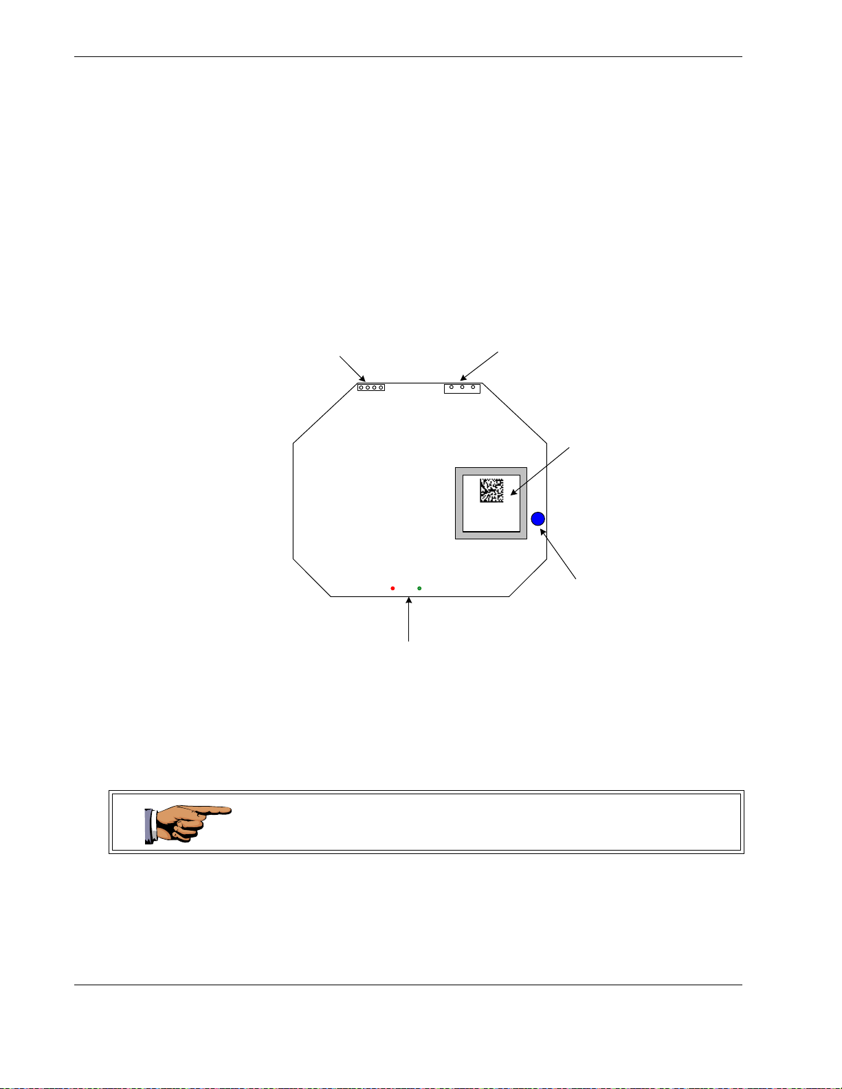
4.1.2 RESI-MON Node Layout
Figure 4.2 below is a simple diagram of a RESI-MON node. The primary
components of the node are:
• the pulse interface connector - connects the node to th e meter
• the DC power connection - supplies power to the node
• the node’s serial number - the node’s unique identifier
• LEDs - red and green lights displaying node’s operating status
Mounting Hol es
Bar Code and label
contain the node’s
radio address and
serial number .
These numbers are
also embedded in
the node’s software .
LED S tat us Lights
Mounting Hol es
Pulse -
Pulse +
FCC ID: P9X-900X
Eka SystemsInc.
+5V DC
GND
Figure 4.2 RESI-MON Node Layout
Each RESI-MON node is uniquely identified with a serial number. This number
is displayed on the label and is contained on the bar code. In addition, the
number is also embedded in the node’s software. This seria l number is the
number displayed on the Field Tool and Network Manager to identify the node.
During installation, it is important to note the Eka Serial Number and the serial
number of the meter in which it is installed in order to map billing data from the
Eka serial number to the meter serial number at the database.
10156-07 4 - 3 EkaNet Hardware Manual
Eka Proprietary and Confidential
Page 27

RESI-MON Node Hardware
4.2 Installation and Operation
To install the RESI-MON node in the RESI-MON meter:
1. Connect the RESI-MON Meter Board to the Pulse Interface Connector on
the RESI-MON Node.
2. Connect the DC power connector on the RESI-MON node to 5V DC power
and ground.
3. Verify that the power polarity is correct before applying power to the device.
As soon as the meter is installed and powered on, the RESI-MON node will
begin operation.
4.2.1 What the Blinking Lights Mean
4.2.1.1 The Green LED
During the initial boot up the green LED may blink unevenly. However after 10
seconds the green LED should begin blinking at a steady r ate of 1/2 second on
and 1/2 second off. This is considered the node’s “heartbeat.” If the green light
fails to come on, is a solid green, or flashes at any other rate, the node has
malfunctioned and the node must be replaced.
4.2.1.2 The Red LED
During the initial boot up the red LED may blink unevenly. During system
operation the red LED will be a solid red whenever it is communicating with any
other Eka node. If the red light flashes continuously, the node has malfunctioned
and the node must be replaced.
EkaNet Hardware Manual 4 - 4 10156-07
Eka Proprietary and Confidential
Page 28

RESI-MON Node Hardware
4.3 RESI-MON Node Specifications
Application Specifications
Compatibility RESI-MON Meter Pulse Interface
Data storage Stores 1 month of data (1 channel @ 15 min. intervals)
Data Integrity Non-volatile data storage provides extra security in the
Advanced features Load profile
Radio Specifications
Operating frequency 902 - 928 MHz
Reliable data transmission Error detection, correction and retransmission
RF output power
Data rate 76.8 Kbps
Receiver sensitivity -93 dBm (@ 0.1% BER, +25°C)
event of communication failure or power outage
1
20 dBm
Range (w/ omni antenna)
Outdoor > 1,000 m (3,200 ft.)
Indoor 75 - 150 m (225 - 490 ft.)
Mode Frequency hopping spread spectrum
1. 20 dBm is the typical output power. The radio hardware is capable of producing up to
30 dBm (1W) of RF output power
Interface Specifications
Dry contact closure pulse inter fa c e
Mechanical
Weight: 34 g (1.2 oz.)
Dimensions: 38 x 127 mm.
(1
1
/2 x 5 1/
in.)
4
10156-07 4 - 5 EkaNet Hardware Manual
Eka Proprietary and Confidential
Page 29

RESI-MON Node Hardware
Network Specifications
No hard limitation on number of meters per Gateway (actual number of meters per
Gateway depends on network performance requirements)
Full peer-to-peer communication
Fully self-configuring
Automatic routing
No network address management required
Automatic network acquisition
Automatic time synchronization of all nodes in the network
128 bit authentication/encryption
Operating Conditions
Environmental -40°C to +70°C
5 - 95% non-condensing humidity
Power Supply Internal to meter
5 volt DC
Power Consumption 0.5 Watt typical
EkaNet Hardware Manual 4 - 6 10156-07
Eka Proprietary and Confidential
Page 30

RESI-MON Node Hardware
10156-07 4 - 7 EkaNet Hardware Manual
Eka Proprietary and Confidential
Page 31

EkaNet Pulse Node Hardware
5. EkaNet Pulse Node Hardware
FCC Notice
Changes or modifications not expressly approved by the party responsible for compliance could void the user’s
authority to operate the equipment.
The Original Equipment Manufacturer (OEM) must ensure that FCC Labeling requirements are
met. This includes a clearly visible label on the outside of the OEM enclosure specifying the
appropriate EKA Systems FCC identifier for this product as well as the FCC Notice below.
Warning
This device complies with Part 15 of the FCC Rules. Operation is subject to the following two
conditions:
(1) This device may not cause harmful interference, and
(2) This device must accept any interference received, including interference that may cause
Warning
undesired operation.
Warning
Warning
This equipment has been tested and found to comply with the limits for a Class B digital device,
pursuant to part 15 of the FCC Rules. These limits are designed to provide reasonable
protection against harmful interference in a residential installation. This equipment generates,
uses and can radiate radio frequency energy and, if not installed and used in accordance with
the instructions, may cause harmful interference to radio communications. However, there is no
guarantee that interference will not occur in a particular installation.
If this equipment does cause harmful interference to radio or television reception, which can be
determined by turning the equipment off and on, the user is encouraged to try to correct the
interference by one or more of the following measures:
• Reorient or relocate the receiving antenna.
• Increase the separation between the equipment and receiver.
• Connect the equipment into an outlet on a circuit different from that to which the receiver is
connected.
• Consult the dealer or an experienced radio/TV technician for help.
The installer of this radio equipment must ensure that the antenna is located or pointed such
that it does not emit RF field in excess of Health Canada limits for the general population;
consult Safety Code 6, obtainable from Health Canada's website www.hc-sc.gc.ca/rpb
.
EkaNet Hardware Manual 5 - 1 10156-07
Eka Proprietary and Confidential
Page 32

EkaNet Pulse Node Hardware
5.1 Overview
The EkaNet pulse node is an external device that provides up to four dry co ntact
closure pulse inputs. The node can interface to multiple meters with pulse
outputs and provides an easy and reliable way to enable meters to form a
wireless mesh network.
EkaNet pulse nodes are available for indoor or outdoor inst allations.
This section describes the procedures to integrate an EkaNet Pulse node with a
meter.
5.1.1 EkaNet Pulse Node Features
EkaNet Pulse nodes:
• operate in 915 MHz license-free bands
• perform automatic time synchronization
• provide real-time access to interval data
• contain local non-volatile data storage
• provide full wireless routing capability
Each EkaNet Pulse node is uniquely identified with a serial number. This
number is displayed on the label and is contained on the bar code. In addition,
the number is also embedded in the node’s softwa re. This serial number is the
number displayed on the Field Tool and Network Manager to identify the node.
During installation, it is important to note the Eka Serial Number and the serial
number of the meter in which it is installed in order to map billing data from the
Eka serial number to the meter serial number at the database.
10156-07 5 - 2 EkaNet Hardware Manual
Eka Proprietary and Confidential
Page 33

EkaNet Pulse Node Hardware
5.2 EkaNet Indoor Pulse Nodes
5.2.1 Layout
Figure 5.1 is a diagram of a EkaNet Pulse node used for an indoor installation.
The primary components of the node are:
• the pulse interface connector - connects the node to th e meter
• the node’s serial number - the node’s unique identifier
• LEDs - red and green lights displaying node’s operating status
Mounting holes (4)
Pulse Connections
Channel 1
Channel 2
Common 1&2
+6 to +12VDC
GND
Channel 3
Channel 4
Common 3&4
Unused
Bar code and label
contain the node’s radio
address and serial
number . These numbers
are also embedded in
the node’s software .
Eka Pulse Board
LED Status Lights
Figure 5.1 Layout of EkaNet Pulse Node for Indoor Installations
EkaNet Hardware Manual 5 - 3 10156-07
Eka Proprietary and Confidential
Page 34

EkaNet Pulse Node Hardware
Mounting holes
(4)
Figure 5.1 shows an indoor EkaNet Wireless Pulse node with the cover
removed. The primary components are labeled:
Pulse Connections
Bar code and label
contain the node’ s
radio address and
serial number. These
numbers are also
embedded in the
node’s software.
Figure 5.2 EkaNet Indoor Wireless Pulse Node - Cover Removed
5.2.2 Connection and Operation
To connect an indoor EkaNet Wireless Pulse node to the meter:
1. Remove the cover from the node.
2. Mount the indoor node such that you can connect the node to the meter(s)
and the node to the power outlet.
3. Connect the meter’s pulse output wires to the EkaNet node’s pulse input
(through the hole of the side of the node’s case).
- For the first meter, connect the meter’s pulse+ output to the EkaNet
- For the second meter , con nect the me ter’s pulse+ output to the EkaNet
- For the third meter, connect the meter’s pulse+ output to the EkaNet
- For the fourth meter, connect the meter’s pulse+ output to the EkaNet
node’s Channel 1 and the meter’s pulse- output to the EkaNet node’s
Common 1&2.
node’s Channel 2 and the meter’s pulse- output to the EkaNet node’s
Common 1&2.
node’s Channel 3 and the meter’s pulse- output to the EkaNet node’s
Common 3&4.
node’s Channel 4 and the meter’s pulse- output to the EkaNet node’s
Common 3&4.
4. Plug in the node’s AC adaptor to a powe r outlet. The EkaNet Wireless Pulse
node will begin operation.
5. Verify that the LEDs are blinking. See Section 5.4.
6. Replace the cover on the node.
10156-07 5 - 4 EkaNet Hardware Manual
Eka Proprietary and Confidential
Page 35

EkaNet Pulse Node Hardware
5.3 EkaNet Outdoor Pulse Nodes
5.3.1 Layout
Figure 5.3 is a diagram of a EkaNet Pulse node used for an out door inst allation.
The primary components of the node are:
• the pulse interface connector - connects the node to th e meter
• the node’s serial number - the node’s unique identifier
• LEDs - red and green lights displaying node’s operating status
Pulse Connections
Common 1&2
Channel 1
GND
Channel 2
+6 to +12VDC
Common 3&4
Channel 3
Channel 4
Red (+6 to +12VDC)
Black (GN D)
Power Supply Board
Unused
Bar code and label
contain the node’s radio
address and serial
number . These numbers
are also embedded in
the node’s software .
Eka Pulse Board
LED Status Lights
White (AC Neutral)
Bl ack ( AC Line )
AC Connection
(Ends loose)
Figure 5.3 Layout of EkaNet Pulse Node for Outdoor Installations
EkaNet Hardware Manual 5 - 5 10156-07
Eka Proprietary and Confidential
Page 36

EkaNet Pulse Node Hardware
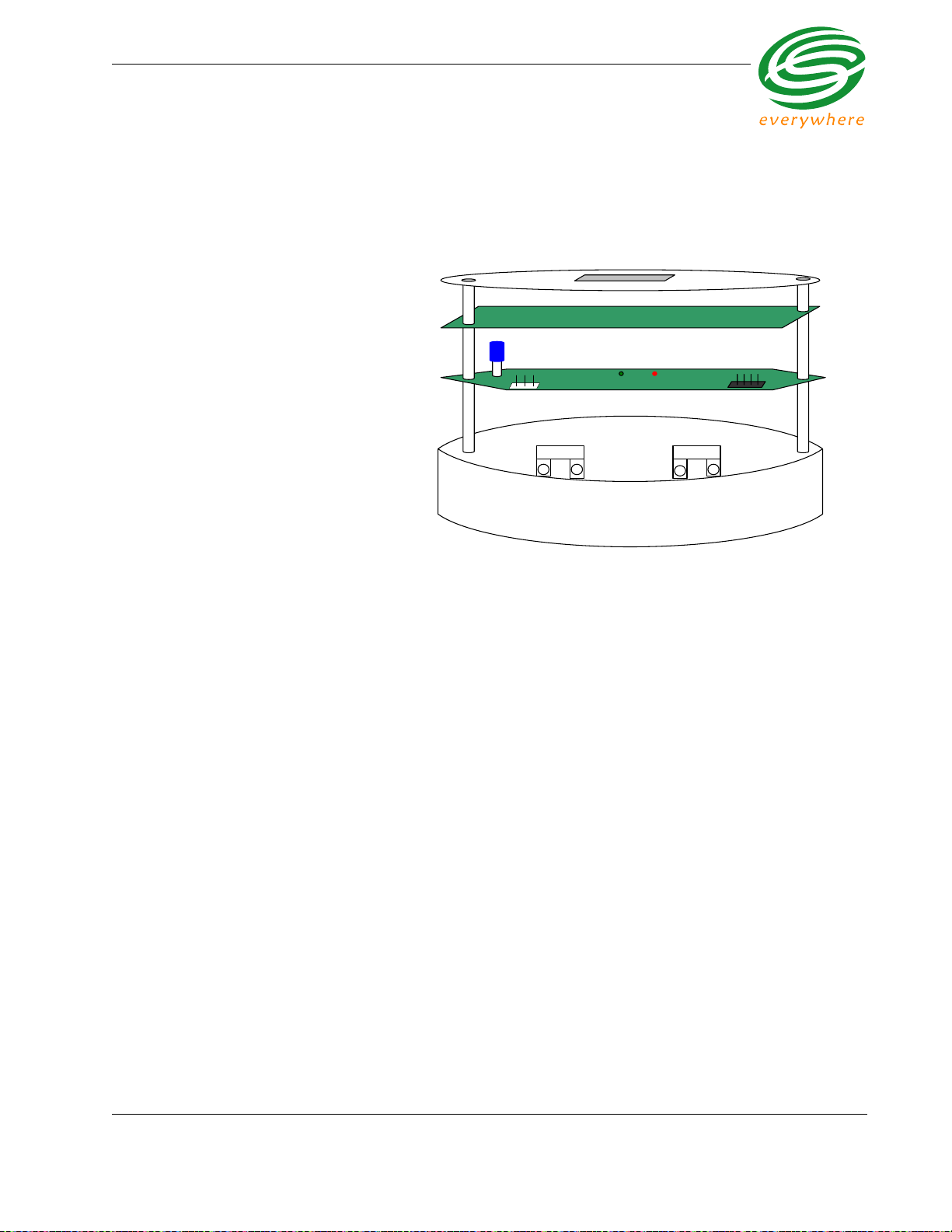
Figure 5.4 shows an outdoor EkaNet Wireless Pulse node with the cover
removed. The primary components are labeled:
Pulse Connections
Bar code and label
contai n the node’s
radio address and
serial numb er. These
numbers are also
embedded in the
node’s software.
AC Connection
Ends Loose
Figure 5.4 EkaNet Outdoor Wireless Pulse Node - Cover Removed
5.3.2 Connection and Operation
To connect the EkaNet Wireless Pulse node to the meter:
1. Verify that the AC power is turned off.
2. Remove the cover from the node.
3. Mount the outdoor node such that you can connect the node to the meter(s)
and the node to the power source (110VAC).
4. Connect the meter’s pulse output wires to the EkaNet node’s pulse input.
- For the first meter, connect the meter’s pulse+ output to the EkaNet
- For the second meter , con nect the me ter’s pulse+ output to the EkaNet
- For the third meter, connect the meter’s pulse+ output to the EkaNet
- For the fourth meter, connect the meter’s pulse+ output to the EkaNet
node’s Channel 1 and the meter’s pulse- output to the EkaNet node’s
Common 1&2.
node’s Channel 2 and the meter’s pulse- output to the EkaNet node’s
Common 1&2.
node’s Channel 3 and the meter’s pulse- output to the EkaNet node’s
Common 3&4.
node’s Channel 4 and the meter’s pulse- output to the EkaNet node’s
Common 3&4.
5. Strip the ends of the AC connections (black and white wires) in the node.
10156-07 5 - 6 EkaNet Hardware Manual
Eka Proprietary and Confidential
Page 37

EkaNet Pulse Node Hardware
6. Attach your AC cable to the AC connections in the EkaNet node (white AC
neutral; black AC line)
7. Turn on AC power. The EkaNet Wireless Pulse node will begin operation .
8. Verify that the LEDs are blinking. See Section 5.4.
9. Replace the cover on the node.
5.4 What the Blinking Lights Mean
5.4.1 The Green LED
During the initial boot up the green LED may blink unevenly. However after 10
seconds the green LED should begin blinking at a steady r ate of 1/2 second on
and 1/2 second off. This is considered the node’s “heartbeat.” If the green light
fails to come on, is a solid green, or flashes at any other rate, the node has
malfunctioned and the node must be replaced.
5.4.2 The Red LED
During the initial boot up the red LED may blink unevenly. During system
operation the red LED will be a solid red whenever it is communicating with any
other Eka node. If the red light flashes continuously, the node has malfunctioned
and the node must be replaced.
EkaNet Hardware Manual 5 - 7 10156-07
Eka Proprietary and Confidential
Page 38

EkaNet Pulse Node Hardware
5.5 EkaNet Pulse Node Specifications
Application Specifications
Compatibility EkaNet Pulse Interface
Data storage Stores 1 month of data (1 channel @ 15 min. intervals)
Data Integrity Non-volatile data storage provides extra security in the
Advanced features Load profile
Radio Specifications
Operating frequency 902 - 928 MHz
Reliable data transmission Error detection, correction and retransmission
RF output power
Data rate 76.8 Kbps
Receiver sensitivity -93 dBm (@ 0.1% BER, +25°C)
event of communication failure or power outage
1
20 dBm
Range (w/ omni antenna)
Outdoor > 1,000 m (3,200 ft.)
Indoor 75 - 150 m (225 - 490 ft.)
Mode Frequency hopping spread spectrum
1. 20 dBm is the typical output power. The radio hardware is capable of producing up to
30 dBm (1W) of RF output power
Interface Specifications
Dry contact closure pulse inter fa c e
Mechanical Indoor Outdoor
Weight:
Dimensions:
13.5 oz. 1 lb 10.5 oz.
4 9/16 in. X 3 1/8 in. X 1 7/8 in. 7 7/8 in. X 4 11/16 in X 3 in.
10156-07 5 - 8 EkaNet Hardware Manual
Eka Proprietary and Confidential
Page 39

EkaNet Pulse Node Hardware
Network Specifications
No hard limitation on number of meters per Gateway (actual number of meters per
Gateway depends on network performance requirements)
Full peer-to-peer communication
Fully self-configuring
Automatic routing
No network address management required
Automatic network acquisition
Automatic time synchronization of all nodes in the network
128 bit authentication/encryption
Operating Conditions
Environmental -40°C to +70°C
5 - 95% non-condensing humidity
Power Supply 110VAC
Power Consumption 0.5 Watt typical
EkaNet Hardware Manual 5 - 9 10156-07
Eka Proprietary and Confidential
Page 40

Gateway Hardware
6. Gateway Hardware
6.1 Overview
The EkaNet gateway is a reliable, fully bidirectional interface between the
Internet/backbone network and the nodes on the local EkaNet wireless network.
6.1.1 EkaNet Gateway Features
EkaNet gateways:
• operate in 2.4 GHz and 915 MHz license-free bands
• act as a bi-directional interface between the Internet and the wireless
Eka nodes
• maintain status information for each node
• contain local storage for up to 45 days of interval data for each node
• provide simple remote configuration of the EkaNet wireless devices
• are available for installation indoors (See Installing an Indoor
Gateway) or a weather-proof version is available for installation
outdoors (See Installing an Outdoor Gateway)
6.2 Configuring the Gateway Using the Field Tool
Before installing the gateway, you must first configure the gateway usin g th e
PDA (Field Tool Survey kit) provided. Complete details on the use of the Field
Tool are provided in the EkaNet Field Tool User Manual.
The instructions below describe the procedures to configure the gateway IP,
NTP server, and user parameters on the compact flash card prior to installation
of the gateway.
Place the gateway’s compact flash card (See “The Compact Flash Card” on
page 6 - 5) into the compact flash slot on the PDA (Field Tool) before
performing this function as all changes made on this tab will be written directly
to the compact flash card.
Select EKA → Gateway Mx Manager → Config on the Field Tool.
Use the Config tab to:
• configure gateway IP, NTP Server, and user parameters on the
• verify gateway settings on the compact flash card
• change gateway settings on the compact flash card
compact flash card
10156-07 6 - 1 EkaNet Hardware Manual
Eka Proprietary and Confidential
Page 41

Gateway Hardware
6.2.1 IP Config Settings
Tap the Config tab to configure gateway IP and user parameters. The
information displayed is dependent upon the configuration type (IP or User)
selected.
Select IP Config from the Config Type
to modify the IP settings.
Figure 6.1 Gateway Maintenance IP Configuration
EkaNet Hardware Manual 6 - 2 10156-07
Eka Proprietary and Confidential
Page 42

Gateway Hardware
6.2.2 User Config Settings
Select User Config as the Config T ype
to modify User settings.
Select Reset to restore the user
settings.
Select Save to save the user settings to
the compact flash card.
Figure 6.2 Gateway Maintenance User Configuration
To modify a user, select the UserID from the drop-down list and make the
necessary changes.
To create a new user:
1. Type the new User Id in the UserID text area
2. Select the Access Level from the drop-down list
3. Complete the Password
4. Reenter the password
5. Tap the Save button.
You may create multiple users before hitting the Save button.
On the Configuration screens, labels will change to a red font when changes
are made to the associated values.
10156-07 6 - 3 EkaNet Hardware Manual
Eka Proprietary and Confidential
Page 43

Gateway Hardware
A confirmation dialog (Figure 6.3) will be displayed after you have successfully
updated the user information.
Figure 6.3 Successful Update to User Information
EkaNet Hardware Manual 6 - 4 10156-07
Eka Proprietary and Confidential
Page 44

Gateway Hardware
6.2.3 NTP Config Settings
Select NTP Config as the Config Type to modify
NTP settings.
Select Remove to remove highlighted server
name from the list of NTP servers.
Select Reload to reload the list of server names
stored on the compact flash card.
Complete the NTP Server using the valid name or
IP address of an NTP (Network Time Protocol)
server and tap Add.
Figure 6.4 Gateway Maintenance NTP Configuration
6.3 The Compact Flash Card
The compact flash card on the gateway contains the EkaNet gateway software
and data collected from the nodes on the network. It may be necessary during
system operation to remove and replace the compact fla sh card with a new card
supplied by Eka.
Power to the gateway must be turned off before removing and/or replacin g the
compact flash card.
To remove the flash card, press the release button next to the compact flash
card. The card will pop out and may be removed. To re-insert the card, slide it
securely back into the slot.
Once the compact flash card has been removed from the gateway it may be
inserted into the Field Tool. Refer to the EkaNet Field Tool User Manual for
instructions on troubleshooting problems with the gateway using the Field Tool.
10156-07 6 - 5 EkaNet Hardware Manual
Eka Proprietary and Confidential
Page 45

Gateway Hardware
6.4 Installing an Indoor Gateway
Y our EkaNet Gateway suit able for indoor installation will be enclosed in a plastic
housing as shown in Figure 6.5.
This housing is not suitable for outdoor installation.
To install an indoor gateway:
1. Attach your ethernet cable to the LAN connection on the gateway.
LAN connection
Figure 6.5 Indoor Gateway
EkaNet Hardware Manual 6 - 6 10156-07
Eka Proprietary and Confidential
Page 46

Gateway Hardware
2. Attach the gateway’s power supply to the 5V connection on the gateway.
3. Plug the power supply into an electrical outlet.
Power
connection
.
Antenna
Figure 6.6 Indoor Gateway - Power Connection
Antenna
Compact
Flash Card
Figure 6.7 Indoor Gateway - Cover Removed
10156-07 6 - 7 EkaNet Hardware Manual
Eka Proprietary and Confidential
Page 47

Gateway Hardware
6.5 Installing an Outdoor Gateway
Your EkaNet Gateway suitable for outdoor installation will be enclosed in a
plastic water-proof housing as shown in Figure 6.8.
Figure 6.8 Weather Proof Outdoor EkaNet Gateway - Closed
EkaNet Hardware Manual 6 - 8 10156-07
Eka Proprietary and Confidential
Page 48

Gateway Hardware
To install an outdoor gateway:
1. Open both latches on the side of the housing to reveal the gateway
hardware inside.
Other
Knock
Outs
Knock Out
Latches
Figure 6.9 Weather-Proof Outdoor Gateway - Latch es
2. Remove the Compact Flash Card from the gateway. (See Figure 6.10)
3. Use the PDA (Field Tool Survey kit) provided to configure the gateway IP,
NTP server, and user parameters on the compact flash card. (See
“Configuring the Gateway Using the Field Tool” on page 6 - 1.)
4. Reinstall the Compact Flash Card in the gateway.
After the gateway is powered up, the compact flash card cannot be removed
for configuration.
5. In order to attach the ethernet cable and the power cable to the gateway
you will first need to remove the knock out through which these cables will
access the electronics inside the housing. There are various knock out
locations on the housing. Use the one that best fits the environment in
which the gateway will be installed.
10156-07 6 - 9 EkaNet Hardware Manual
Eka Proprietary and Confidential
Page 49

Gateway Hardware
Antenna
Ethernet
Connection
Compact Flash Card
Ethernet Cabl e
LED Status Light
Top Assem b ly Part #/
Seria l #
AC Power
Connection
Terminals
Link Light - Green
Activity Light - Yellow
GND
L
N
Figure 6.10 Internal Components of an Outdoor Gateway
6. Connect your ethernet cable to the ethernet connection in the gateway.
During normal system operation the Activity light (yellow) on the ethernet
connection will blink occasionally and the Link light (green) will be
illuminated at all times.
EkaNet Hardware Manual 6 - 10 10156-07
Eka Proprietary and Confidential
Page 50

Gateway Hardware
7. Connect the input power wires (line marked L, neutral marked N, and
ground marked ) to the appropriate power input terminals in the
gateway.
8. Install the gateway at its predetermined location.
Figure 6.11 Power Input Terminals on an Outdoor Gateway
6.6 Verifying Gateway Connectivity
A crossover ethernet cable was supplied with your EkaNet Field Tool.
To use this cable to verify that the gateway is reachable:
1. Remove your ethernet cable from the gateway.
2. Plug in one end of the crossover cable into the ethernet connection on the
gateway.
3. Plug the other end of the crossover cable into the ethernet adapter on the
Field Tool.
Refer to the EkaNet Field Tool User Manual for instructions on troubleshooting
problems with the gateway using the Field Tool.
AC Power Conn ection
Terminals
10156-07 6 - 11 EkaNet Hardware Manual
Eka Proprietary and Confidential
Page 51

Gateway Hardware
6.7 Gateway Specifications
Application Specifications
TCP/IP Ethernet 10 BaseT
AMD SC-520 microprocessor
128MB flash (1 channel @15 min. interval for 1000 meters for 1 month)
Linux Operating System
Secure Sockets Layer (SSL) communications
Radio Specifications
Operating frequency 903-928 MHz 2.400-2.4835 GHz
Reliable data
transmission
RF output power
Data rate 76.8 kbps 1 Mbps
Receiver sensitivity Max transmit power 20
Range (w/ omni antenna)
Indoor
Mode Frequency hopping
Outdoor
Error detection,
correction and
retransmission
1
20 dBm
dBm
Sensitivity -93 dBm (@
0.1% BER, +25°C)
> 1000 m (3000 ft.)
75 - 150 m (225 - 450 ft.)
spread spectrum
Error detection,
correction and
retransmission
20 dBm
Max transmit power 20
dBm
Sensitivity -80 dBm (@
0.1% BER, +85°C)
> 400 m (1200 ft.)
25 - 50 m (75 - 150 ft.)
Frequency hopping
spread spectrum
1. 20 dBm is the typical output power. The radio hardware is capable of producing up to
30 dBm (1W) of RF output power.
Interface Specifications
Hardware interface: RJ-45 - 468B
Mechanical
Indoor Weight: 382 g. (13.5 oz.)
Dimensions: 17.1 x 13.3 x 5.7 cm.
(6 ¾ x 5 ¼ x 2 ¼ in.)
Outdoor Weight: 1492 g. (52.6 oz.)
Dimensions: 27.9 x 19 x 12 cm.
(11 x 7.5 x 4¾ in.)
EkaNet Hardware Manual 6 - 12 10156-07
Eka Proprietary and Confidential
Page 52

Gateway Hardware
Network Specifications
No hard limitation on number of meters per Gateway (actual number of meters per
Gateway depends on network performance requirements)
Full peer-to-peer communication
Fully self-configuring
Automatic routing
No network address management required
Automatic network acquisition
Automatic time synchronization of all nodes in the network
128 bit authentication/encryption
Operating Conditions
Environmental -40°C to +85°C
5 - 95% non-condensing humidity
Power Supply 110 - 240 VAC, 12W
10156-07 6 - 13 EkaNet Hardware Manual
Eka Proprietary and Confidential
 Loading...