

Cooper Menvier 520r, 525r, 536r, 524r, 502r Installation Manual
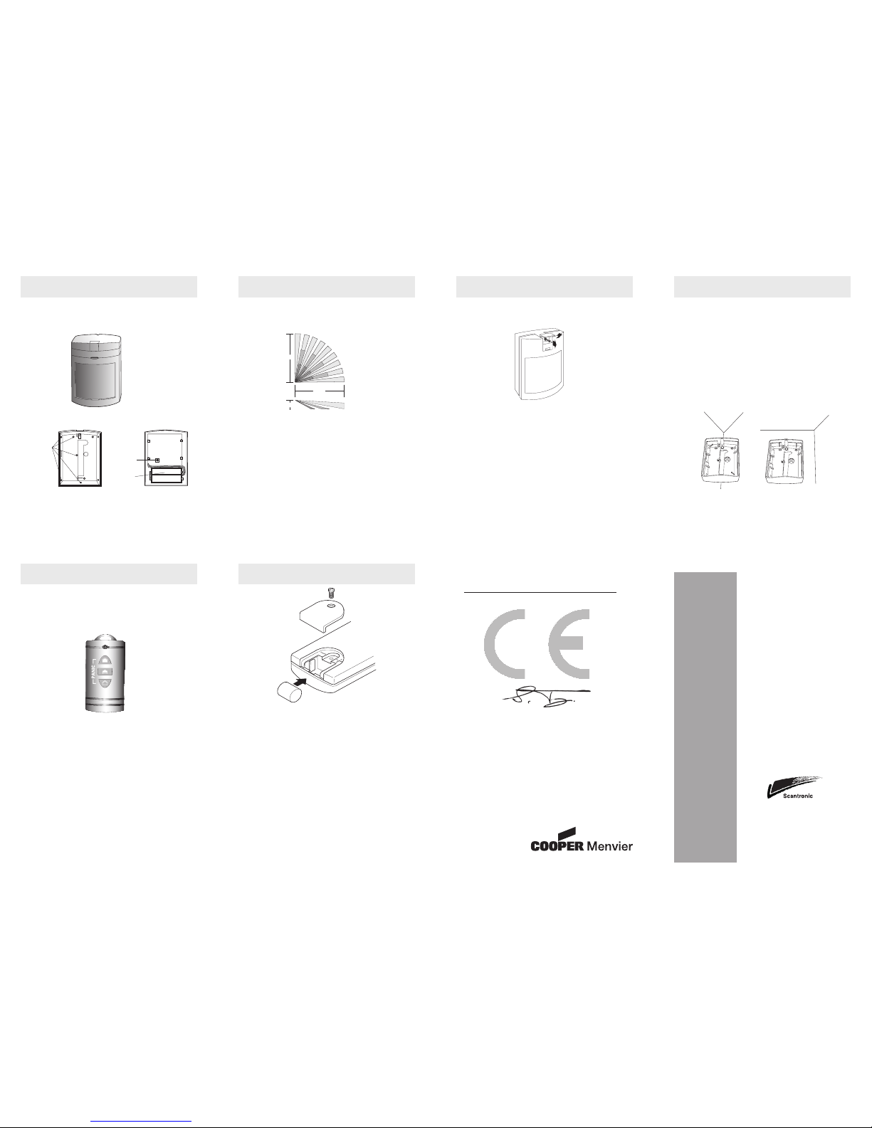
1. 520r PIR
Introduction
The 520r Passive Infra Red (PIR) is an indoor detector designed to work with the 500r wire
free control panel. The PIR detects movement. The detector has a fan shaped sensitive area
approximately 10 metres in radius.
The case is protected by an internal tamper switch.
Specification
Part No. 520rEUR-50
Power Supply 2 x AA alkaline cells
Battery Life Approximately 14 months
Temperature Range -10 to +50 °C
Fixing hole
cutouts
Back
Body
Tamper
Battery
case
+
+
2. 520r PIR
Siting
You can mount the unit either flat against the wall, or in a corner. The area covered by the
detector is shown below:
DO mount the unit:
Between 2 and 2.5 metres high for the best general coverage in an average room
Do NOT mount the unit
Facing a fire, boiler or window.
Over a radiator.
Near the floor. close to or on large metal structures.
Closer than one meter to mains wiring and metal water or gas pipes.
Inside steel enclosures .
Next to electronic equipment, particularly computers, photocopiers or other radio
equipment.
Closer than 3cm to a ceiling (to allow space for dismounting the unit in the future).
10m
10m
2m
3. 520r PIR
Installation
Open the detector by lifting the flap and removing the screw from the case.
Install two ‘AA size alkaline batteries (not supplied). Do not use rechargeable (Nickel
Cadmium) batteries, because they are 1.2V and not 1.5V.
Learning
See “Programming - Learning Detectors” in the 500r+ Installer’s Guide.
Testing.
1. Put 500r Wirefree Control Panel into walk test (user code + 1).
2. Open and close the tamper for each detector (this will start the test mode).
Note: After opening and closing the tamper, the detector remains in test mode for half an
hour. In this mode the detector has a 30 second lockout time. At the end of half an hour the
detector reverts to normal mode, with a 3 minute lockout time.
3. Make sure the panel receives the alarm from each detector.
4. Chose another site for the detector if the panel does not receive the signal.
5. Wait thirty seconds with no movement in front of the detector before triggering it
again.
6. Press RESET on the control panel when you have finished testing, to put the panel
back into user mode.
4. 520r PIR
Walk Testing and Lockout
In normal use the 520r uses a three minute lockout timer in order to extend battery life. The
lockout timer works like this:
a) The unit detects movement, signals the panel, and starts the lockout timer.
b) If the unit detects movement while the lockout timer is running, then it restarts the
lockout timer but DOES NOT signal the panel.
c) When the lockout timer expires the unit signals the panel the next time it detects
movement.
If you want to test a 520r PIR in normal use you should wait at least three minutes between
activations. To make testing easier the detector changes the lockout period to 30 seconds for
the first half hour after you put the batteries in, or after you trigger its tamper.
Mount the back
There are a number of possible fixing holes in the back of the PIR marked by mouldings in
the plastic. Chose two to suit the location you have selected, and drill them out carefully.
1. Hold the back in location and mark and drill 5 fixing holes in the wall.
2. Secure the back to the wall with 16mm countersunk head screws and wall plugs.
3. Clip the body of the detector to the back.
5. 525r Remote Setting Device
Introduction
The user can employ the 525r Remote Setting Device to set, un-set and part set the 500r
Wirefree Control Panel. In addition, pressing Arm and Off at the same time will cause a Panic
Alarm. The 500r Wirefree Control Panel can use up to three 525r Remote Setting Devices.
Specification
Part No. 525rEUR-00
Power Supply Duracell DL 1/3N or CR 1/3N or K58L (Alkaline)
RS Part No. 596-040. Farnell Part No. 300-469
Battery Life Approximately 14 months.
Temperature Range -10 to +50 °C
Learning
The control unit stores the Remote Setting Device’s identity in the same “hidden” zone as
the 502r PAs and 524r keypads. The 500r+ can learn any mixture of keypads, 502 PAs, or
Remote Setting Devices provided the total number of devices does not exceed six.
See “Programming - Learning Detectors” in the 500r+ Installer’s Guide.
Changing the Battery
1. Undo the screw holding down the battery compartment cover.
2. Slide back the cover.
3. Replace the battery (make sure the battery polarity is correct).
4. Replace cover and tighten screw (do not overtighten).
Note: The battery can be obtained from Cooper Security Limited Service Department.
6. 525r Remote Setting Device
© Cooper Security Limited 2004
Every effort has been made to ensure that the contents of this leaflet are correct . However,
neither the authors nor Cooper Security Limited accept any liability for loss or damage caused
or alleged to be caused directly or indirectly by this leaflet. The contents of this leaflet are
subject to change without notice.
Printed and published in the U.K.
PIR
Remote Setting
Device
Universal
Transmitter
Keypad
Pendant
Installation Guide
Cooper Security Ltd
Security House
Vantage Point Business Village
Mitcheldean
Gloucestershire
GL17 0SZ
Product Support (UK) Tel: +44 (0) 870 757 5400. Hours:
08:15 to 17:00 Monday to Thursday,
08:15 to 12:45 Friday.
12:45 to 17:00 Friday emergency service only.
(CALLS CHARGED AT 60p PER MINUTE)
Product Support Fax: (01594) 545401
Part No. 496926 Issue 1
-ve terminal
Battery
+ve terminal
520r, 525r, 536r, 524r, 502r
DECLARATION OF CONFORMANCE
Cooper Security Ltd issues this certificate
to certify that the equipment know as:
515r, 525r, 535r, 524r and 502r
Complies with the following directive:
1995/5/EC R&TTE Directive
Signed
Stewart Taylor, Technical Director
Date: 12 January 2004
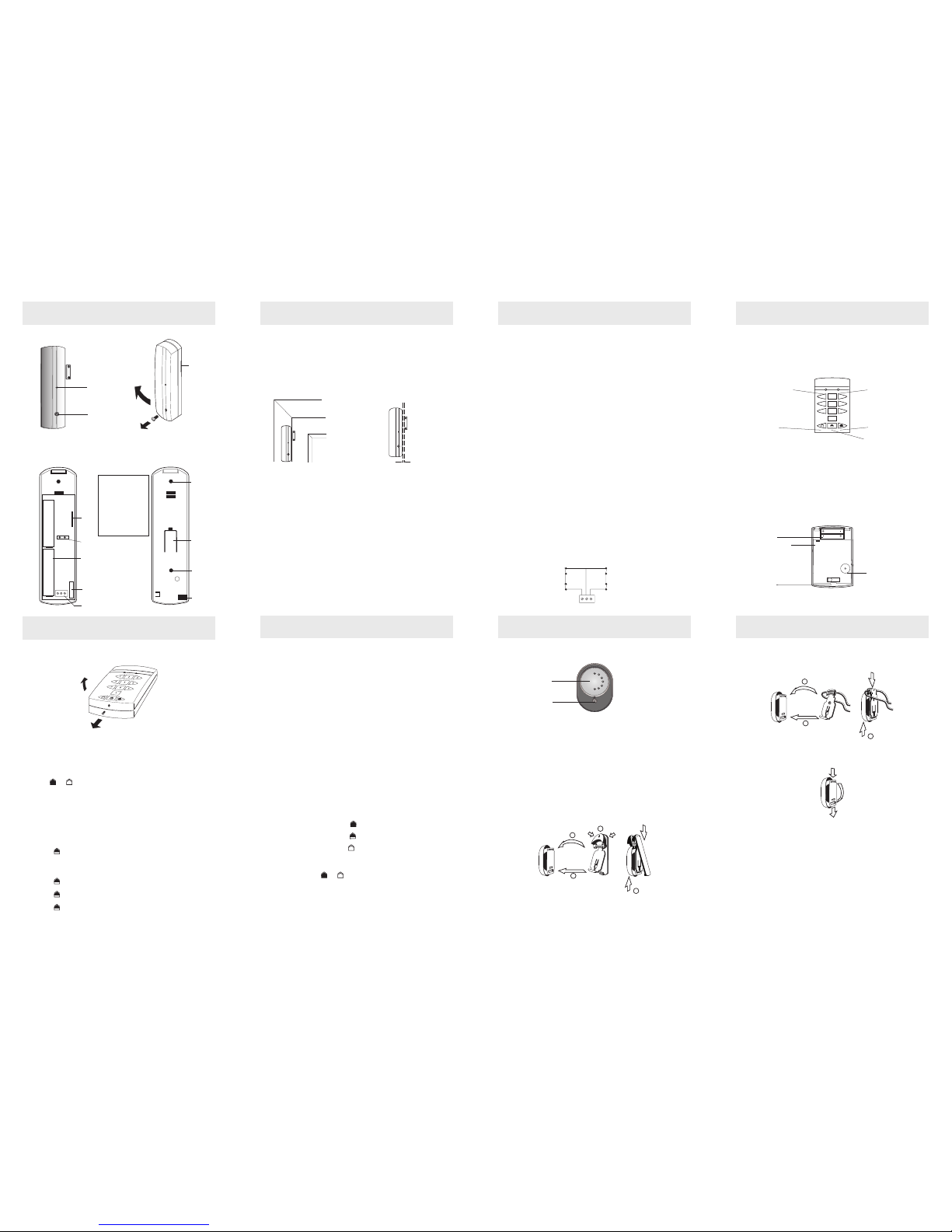
Fitting the Pendant
1. Fit the bottom of the pendant attachment into the lower attachment slot.
2. Push the lugs at the top of the pendant attachment over the groove at the top of
the transmitter.
3. Slide the transmitter up the pendant attachment until it clicks home.
1
2
3
Fitting the Wrist Strap
Thread the elasticated wrist strap in and out of the attachment slots as shown in the diagram.
Learning
The control unit stores the 502r Wrist Pendant’s identity in the same “hidden” zone as the
525r Remote Setting Devices and 524r Remote Keypads. The 500r+ can learn any mixture of
502 PAs, 524r keypads or 525r Remote Setting Devices provided the total number of devices
does not exceed six.
See “Programming - Learning Detectors” in the 500r+ Installer’s Guide.
7. 536r Universal Transmitter
Introduction
The 536r Universal Transmitter is designed to work with the 500r Wirefree Control Panel. The
transmitter signals the alarm panel when the associated magnet moves away from the case,
and sends a restore signal when the magnet is realigned. The case is protected by an internal
tamper switch
8. 536r Universal Transmitter
Specification
Part No. 536rEUR-50
Power Supply Two AAA Alkaline batteries
Battery Life Approximately 14 months.
Temperature Range -10 to +50 C
Siting
Where possible, mount the body of the transmitter close to the top of the non-moving frame
of a door or window, and the magnet on the moving part.
If the frame is not wide enough, mount the magnet on the frame and the body on the
moving part.
DO:
Make sure there is less than 10mm between magnet and transmitter body with the
door/window closed.
Make sure the magnet aligns with the mark moulded into the side of the case with the
door/window closed.
Do NOT mount the unit:
On the hinged edge of the door.
Near the floor.
Close to or on large metal structures.
Closer than one meter to mains wiring and metal water or gas pipes.
Inside steel enclosures.
Next to electronic equipment, particularly computers, photocopiers or other radio
equipment
Using the Internal Reed
If you plan to use the internal reed switch then YOU MUST REMOVE THE JUMPER FROM
LK1. (If you wish to retain the jumper link fit it onto one pin only. If at a later date you wish
to connect wire-in contacts you must refit the jumper link over both pins.)
-ve
+ve
-ve
LK1
+ve
AL TA
9. 536r Universal Transmitter
Installation
Open the transmitter by undoing the cover screw and lifting the front away. Install two
“AAA” size alkaline batteries (not supplied). Do not use rechargeable (Nickel Cadmium)
batteries, because they are 1.2V and not 1.5V.
Learning
See “Programming - Learning Detectors” in the 500r+ Installer’s Guide.
Testing.
1. Put the 500r Wirefree Control Panel into walk test (user code + 1).
2. Hold the detector in place.
3. Trigger the tamper.
4. Make sure the panel receives the alarm.
5. Chose another site for the detector if the panel does not receive the signal.
6. Press RESET on the control panel when you have finished testing, to put the panel
back into user mode.
Mount the back
1. Hold the back in the chosen location.
2. Mark two holes through the fixing slots in the back.
4. Secure the back to the surface using two Type ‘C’ 15mm Domehead screws.
5. Make sure the back is flush against the surface and pushes the tamper bar in far
enough to activate the tamper switch.
6. Fit the body of the unit into the back.
Connecting External Door Contacts or N.C. Switches
You can wire external Normally Closed devices (for example the 20mm Quikfit) to the 536r
Universal Transmitter. You can connect several contacts in series, but the panel will treat
them all as one zone. Do not use more than 10m total cable length from the 536r to the last
external contact
1 . Remove the wire links from the connector.
2. Connect Normally Closed contacts wired as shown.
3. Fit the jumper over both pins of LK1.
If you remove the external contacts at a later date, make sure you replace the wire links on
the Alarm and Tamper connectors.
Tamper
circuit
Alarm
circuit
AL TA
Cable entry
Tamper bar
Fixing hole
Fixing hole
Connector
block
Battery
holder
Tamper
switch
Internal reed
shunt link
Reed
switch
Note:
FIT JUMPER TO LK1
if using the connector
block and not the
onboard reed switch.
DO NOT FIT JUMPER
if using the onboard
reed switch.
10. 524r Remote Keypad
Introduction
The 524 Remote Keypad can accept a user code from three to eight digits long and allows
the user to set and unset the alarm system, and if necessary activate a PA (Panic Alarm).
The control unit stores the keypad’s identity in the same “hidden” zone as the 525r Remote
Setting Devices. The 500r+ can learn any mixture of keypads, 502 PAs, or Remote Setting
Devices provided the total number of devices does not exceed six.
1
2 3
4
5 6
7
8 9
0
Specification
Part Number 524rEUR-00
Display Two LEDs (Low Battery and Transmission).
Compliance Product is CE tested to EN 50081-1 and EN 50082-1.
Radio Section Operating frequency: 433 MHz at 200 kHz bandwidth.
Temperature range -10 to +50°C.
Internal Sounder Piezo, for key clicks and confirmation tones (not entry/exit
tones).
Battery 2 x AAA. (Not provided.)
Battery Life Approximately 14 months.
Dimensions h x w x d = 136 x 90 x 31 mm.
Weight 0.19 kg. (with batteries).
Installation
1. Put the control unit into programming mode (See “Programming - Learning
Detectors” in the 500r+ Installer’s Guide.).
2. Open the 524 case.
3. Insert two new AAA batteries in the battery compartment. Make sure the batteries are
oriented correctly.
Note: In a high risk environment Cooper Security Ltd recommend that you replace the screw
holding the keypad together with a tamper-proof M3x8 screw (not available from
Cooper Security Ltd).
4. Make sure that the red activity LED of the keypad is close to and facing the learn
sensor on the control unit.
5. Press
and together to activate the PA. The control unit learns the keypad.
6. Mount the back of the keypad case in an appropriate location.
7. Refit the keypad front.
Programming
Changing the User Code
The user can store a single access code on the keypad. The access code can have between
three and eight digits, and does not have to be the same as the access code for the control
unit. Do not use “0” as the first digit of the keypad access code.
1. Press
.
The red LED glows.
2. Key in the current access code. If this keypad is fresh from the factory, or you have
reset the user code (see below) then key in “1234”.
3. Press
.
4. Key in the new user code. (Minimum three digits, eight digits maximum)
5. Press
.
6. Key in the new user code again.
7. Press
.
The keypad beeps twice and flashes the red LED to indicate that it has accepted the new
code. If the keypad gives a low error tone then it has not accepted the new code, and not
changed the current code.
Resetting a User code
If a user forgets their code then you can reset the access code to “1234” by following the
instructions below.
1. Place the control unit in programming mode (see “Programming - Learning Detec
-
tors” in the 500r+ Installer’s Guide).
2. Open the case. Note that the keypad does not send a tamper signal to the control
unit.
3. Remove the batteries.
4. Short the two reset pins together with a screw driver.
5. Re-fit the batteries (make sure you insert them the correct way round).
The keypad resets the access code to “1234”.
6. Remove the short on the reset pins.
7. Take the control unit out of programming mode.
The keypad now has the default access code “1234”.
Please note that if you try to reset the keypad access code without placing the control unit in
programming mode then the alarm system will sound a PA alarm. This is a security precaution
to prevent unauthorised tampering. To stop the PA alarm you must enter the default user
code for the keypad.
Operation
Setting, Part Setting, and Unsetting
Setting: Access code +
Part Setting: Access code +
Unsetting: Access code +
PA Alarm
To activate a PA alarm press and together.
Low Battery
The keypad flashes the yellow LED during transmission when its battery is low.
12. 524r Remote Keypad 13. 502r Wrist Pendant
Sounder
The 502r transmitter comprises a plastic waterproof case that can either be worn on a strap
round the wrist, round the neck as a pendant, or clipped to a pocket. The aerial is inside the
case, and the unit is powered by a long life lithium battery.
Operation
To use the transmitter press the large orange button. The unit sends a signal to the 500r+ and
briefly lights the small red lamp to show that it is working. If you hold the button down, the
transmitter continuously repeats the signal .
NOTE: You must check that the range of the pendant is suitable for the application.
WARNING This product contains a Lithium battery. Do not destroy in a fire. Do not attempt
to open the unit. Do not crush or puncture. Do not expose to temperatures above 60°C.
Contact your local authority for disposal procedure.
Fitting The Pocket Clip
1. Squeeze the top of the clip to open it.
2. Put the bottom lip of the clip in the lower attachment slot.
3. Push the lugs at the top of the clip over the groove at the top of the Transmitter.
4. Slide the Transmitter up the clip until it clicks home.
1
2
3
4
Low Battery LED
(yellow)
Activity LED
(red)
Unset key Set key
Part Set key
Batteries
Transmitter
module
Reset pins
Note: There is no tamper
switch fitted to this product.
11. 524r Remote Keypad 14. 502r Wrist Pendant
Button
Red lamp
Magnet
alignment
mark
Magnet
Activity
LED
Cover
screw
 Loading...