

Page 1
SC-UN/SC-UN-FT
Universal Source Controller
Programming Guide &
User Manual
Page 2

Contents
Important Information 3
Introduction 4
Welcome 4
Product Overview 4
Terminology used in this guide 5
Basic Control Panel Operation 7
Using the control panel 7
Menu navigation 8
Accessing the menus 9
Menu layouts 9
Commissioning an Installation 11
1: iCANnet control wiring 12
2: Visually inspect all wiring & components 14
3: Power up the Source Controller 16
4: Energize each Output one at a time to
determine the location, type and
current draw of its load. 17
5: Congure Output behaviors 20
6: Remove the bypass jumpers on
used Outputs. 23
7: Covers and Source Controller and
power the unit 23
8: Verify proper control of each Output
using the Output Override option 24
9: Congure Scene Values 25
10: Edit the Emergency Scene 26
11: Connect and congure contact inputs 27
12: Congure wallstations using the
Wallstation Wizard 28
13: Verify each wallstation 30
14: Enable the timeclock 30
15: Congure the time, date, coordinates
and daylight saving time 31
16: Congure timeclock events 33
17: Congure Ethernet 35
18: Congure DMX 36
19: Congure passwords 38
Other Useful Features 39
Overriding Outputs 40
Viewing power data 40
Choose communications 41
Restore default settings 41
Appendix 1 42
Placing wallstations into announce mode 42
Index 43
P2
See page 11 for the list of commissioning steps
Page 3

Important Information
• Do not discard this programming guide. Please keep
for future reference.
• Please read and follow all warnings given in this guide.
• Always disconnect all power before wiring.
• Use only as intended and at the listed voltage.
• All installation service must be performed by qualied
personnel or service technicians.
• Install in accordance with National Electrical Code
(NEC) and any other codes that may apply.
• High Voltage is present inside the enclosure. Use
extreme caution when performing maintenance on this
equipment. Failure to follow this warning and proper
safety procedures could result in severe injury or death
and/or damage to the equipment.
• Document all wiring that is terminated at the Source
Controller so that the system can be properly cong-
ured and programmed for operation.
P3
Page 4
Introduction
Welcome
The iLumin SC-UN Universal Source Controller from Cooper Lighting Solutions has been designed to provide exibility
in both installation and operation. Each model in the product family can accept a variety of industry standard control
options including iCANbus, DMX, Ethernet, and RS485. Also, every model can drive a wide range of lighting source
types in-cluding incandescent, dimmable uorescents, LEDs, neon/cold cathode, MLV (Magnetic Low Voltage), ELV
(Electronic Low Voltage), and non-dimmable uorescents.
All Universal Source Controller models feature a fold-out control panel which provides access to an intuitive conguration menu to allow quick and exible conguration.
This guide provides full information about programming the Source Controller using the control panel. For details about
mounting and connecting iLumin SC-UN Universal Source Controller products, please refer to the accompanying Installation Guide (73-830-00 IM8476), for Feed Thr ough Panel refer to Installation Guide (73-833-00 IM8853.
Product Overview
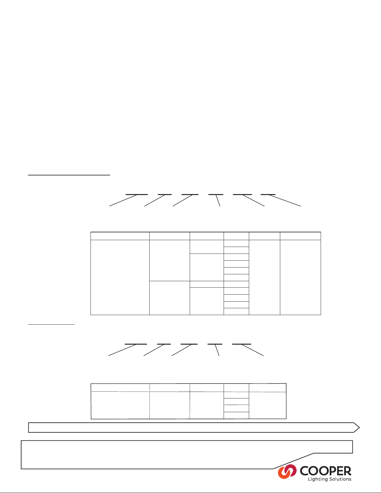
Each model is specied using a part number in the following format:
For SC-UN with Breakers
SC120-06-UN-1P-ML-20
For SC-UN-FT
Supply voltage:
120 for 120VAC
277 for 277VAC
Model number Supply voltage Supply type Outputs Feed Maximum load
SC120-06-UN-1P-ML-20 120VAC 1 phase 6 Main lugs 16A per channel
SC120-12-UN-1P-ML-20
SC120-06-UN-3P-ML-20
SC120-12-UN-3P-ML-20
SC120-18-UN-3P-ML-20
SC120-24-UN-3P-ML-20
SC277-06-UN-1P-ML-20
SC277-06-UN-3P-ML-20
SC277-12-UN-3P-ML-20
SC277-18-UN-3P-ML-20
SC277-24-UN-3P-ML-20
Outputs:
06
12
18
24
24
24
Type:
UN - Universal
3 phase 6
277VAC
1 phase 6
3 phase 6
Supply type:
1P - Single phase
3P - Three phase
12
12
18
12
18
Panel feed:
ML - Main Lugs
Circuit breaker rating:
20 - 20A
SC277-06-UN-1P-FT
Supply voltage:
277 - 120 to 277 VAC
Model number Supply voltage Supply type Circuits Maximum load
SC277-06-UN-1P-FT 120 to 277VAC 1 phase 6 16A per channel
SC277-12-UN-1P-FT
SC277-18-UN-1P-FT
SC277-24-UN-1P-FT
Channels:
06
12
18
24
Type:
UN - Universal
Supply type:
1P - Single phase
Panel feed:
FT - Feed Through
12
18
24
P4
See page 11 for the list of commissioning steps
Page 5

Terminology Used in this Guide
This guide uses standard terminology to describe the various aspects of equipment and operation. This brief section
provides an overview of certain terms.
Source Controller
A cabinet containing power dimming and/or switching circuitry to which lighting (or other) loads are
directly connected.
Control Panel
A compact fold out console which is contained
within the front panel door of the SC-UN Source
Controller. The control panel has an LCD screen
and a keypad, and permits many conguration settings to be made to the SC-UN Source Controller.
Output
An Output is physical circuit where electrical loads
are connected and controlled. SC-UN Source
Controllers can have between six and twenty four
separate Outputs, depending on the model.
All SC-UN Outputs can be congured to dim or
switch high voltage loads and can also provide low
voltage dimming control signals where required.
Each Output within the SC-UN Source Controller
has a physical number which cannot be altered.
Zone
A Zone is a virtual representation of one or more
Outputs. For instance, a room might contain three
lights, each of which is connected to a separate
Output on the Source Controller. If all three lights
need to be switched On or dimmed in the same
way, then it makes sense to represent them all as a
single Zone.
The Outputs represented by a Zone do not need to
be within the same Source Controller, they could
be spread across any number of different Source
Controllers.
Once the Outputs are represented by a Zone, the
physical number related to each Output is only of
relevance within the Source Controller that contains
it. To all other devices, the Zone is the only item of
interest.
Scene
A Scene is a collection of settings for any number of
Zones. They are the equivalent of cues in theatrical
lighting.
For example, a hotel restaurant has breakfast, lunch
and evening sittings. There are four Zones: Ceiling
spots, wall washers, chandeliers and table lights.
The manager wants to create a different mood for
each sitting. Rather than adjusting each of the
four Zones individually every time, you can collect
different dimming levels for the channels into three
separate Scenes (one for each sitting) and apply
each to a different button on the wallstation.
Changing between the sittings becomes simple and
consistent thanks to easy Scene selection.
Area
An Area is a collection of one or more Zones that
might have related operations. The most common
example for an Area would be a single room.
Imagine a restaurant with three zones: main ceiling
lighting, worktop task lights and a pendant lamp
over the table. The room has two wallstations.
By grouping the three Zones into a single Area, it
becomes straightforward to allow each wallstation
to adjust any of the Zones within the room.
Contact Closure Input
Each Source Controller has two volt-free contacts
which can be used to accept inputs from external
devices like re and intruder alarms so that lighting
can be automatically taken to a predetermined level
to assist with visibility.
Source Type
There are many different technologies that are used
in today’s buildings to create light. Incandescent,
Fluorescent (dimmable and non-dimmable), LED,
Neon/Cold Cathode, MLV - Magnetic Low Voltage,
and ELV - Electronic Low Voltage are examples of
source types.
P5
Page 6

Wallstation
A wall mounted User Interface with either physical
buttons or a touchscreen that allows occupants of
a room to adjust lighting levels or controlling other
devices like A/V equipment or shades.
Device
Any iLumin equipment. For example, an Ineo is a
Device. A Source Controller is also a Device.
Node
Any iLumin Device connected to the iCAN network.
For example, Source Controllers, Ineo’s and Revio’s
connected to the iCAN network are Nodes.
Segment
Devices connected together on the iCAN network
in a daisy chain. Each Segment is terminated with
120-ohm resistors at both ends of the daisy chain.
A Segment can contain up to 100 Nodes.
P6
See page 11 for the list of commissioning steps
Page 7
Basic Control Panel Operation
ESC
1 2
0
ENT
3
4 5 6
7 8 9
#
iCAN
DMX
485
DATA
OK LINK
Device 255 - 129
iCAN
DMX
485
DATA
OK LINK
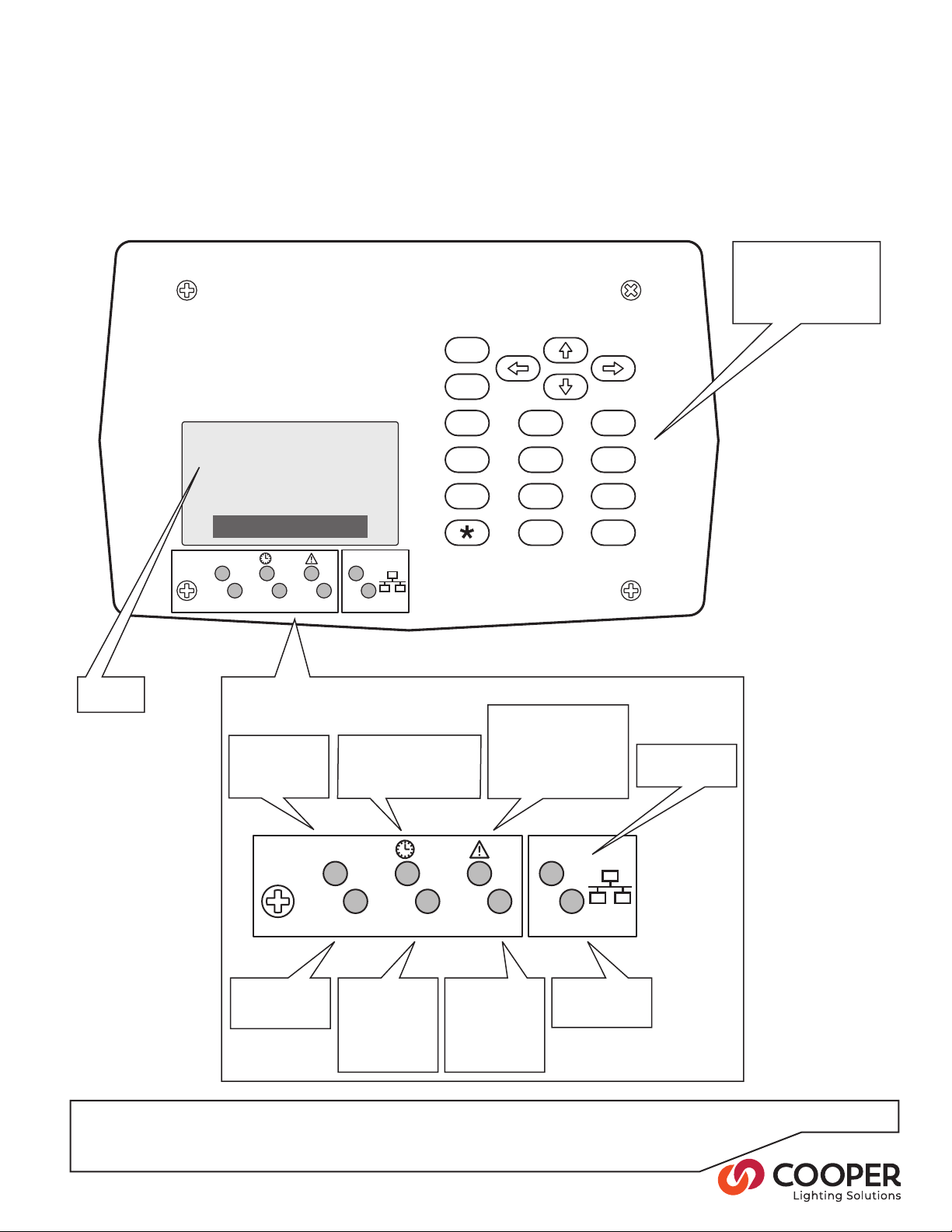
Using the Control Panel
Each Universal Source Controller provides a control panel to make programming and operation as straightforward as
possible. To access the control panel, open the main panel door on the front of the unit.
Numeric keypad for
menu navigation
Cooper Lighting
Solutions
21:56
August 14, 2008
Clear text
display
Link and status indicators
Flashes regu-
larly to indicate
correct system
operation
Flashes when
data is present
on iCANbus link
When On, indicates that
the timeclock function is
enabled.
On when DMX
link is enabled,
ashes when
data is present
on
DMX link
Flashes when
data is present
on RS485 link
Illuminates when an
error condition occurs.
The display screen
will provide further
information about the
nature of the fault
Flashes when
data is present
on Ethernet link
On when valid
Ethernet link
detected
P7
Page 8

Menu Navigation
ENT
ESC
Within the control panel menu system, use the following
buttons to navigate:
Press to select an item or to save
changes.
Press to enter an option or select an item.
Press to escape from an option and return to the
previous level.
The Asterisk will be used on some Scenes to per-
form special functions.
The menu system is comprised of two main sections:
• The Operation menu
Contains functions for users to operate the system. Functions include: Output override, Timeclock functions, Power
data figures, etc.
• The Conguration menu
Provides functions primarily used during initial commissioning and subsequent fine tuning of the installation by engineers.
To prevent unauthorized access, use the Password Man-
ager to congure four-digit passwords for the Operation
and Conguration menus.
Please see the next pages for more detailed information
about the Operation and Conguration menus.
See page 11 for the list of commissioning steps
P8
Page 9
Device 255-129
Help
OutputOverride
TimeclockManager
PowerData
OperationMenu
Accessing the Menus
ENT
ENT
ENT
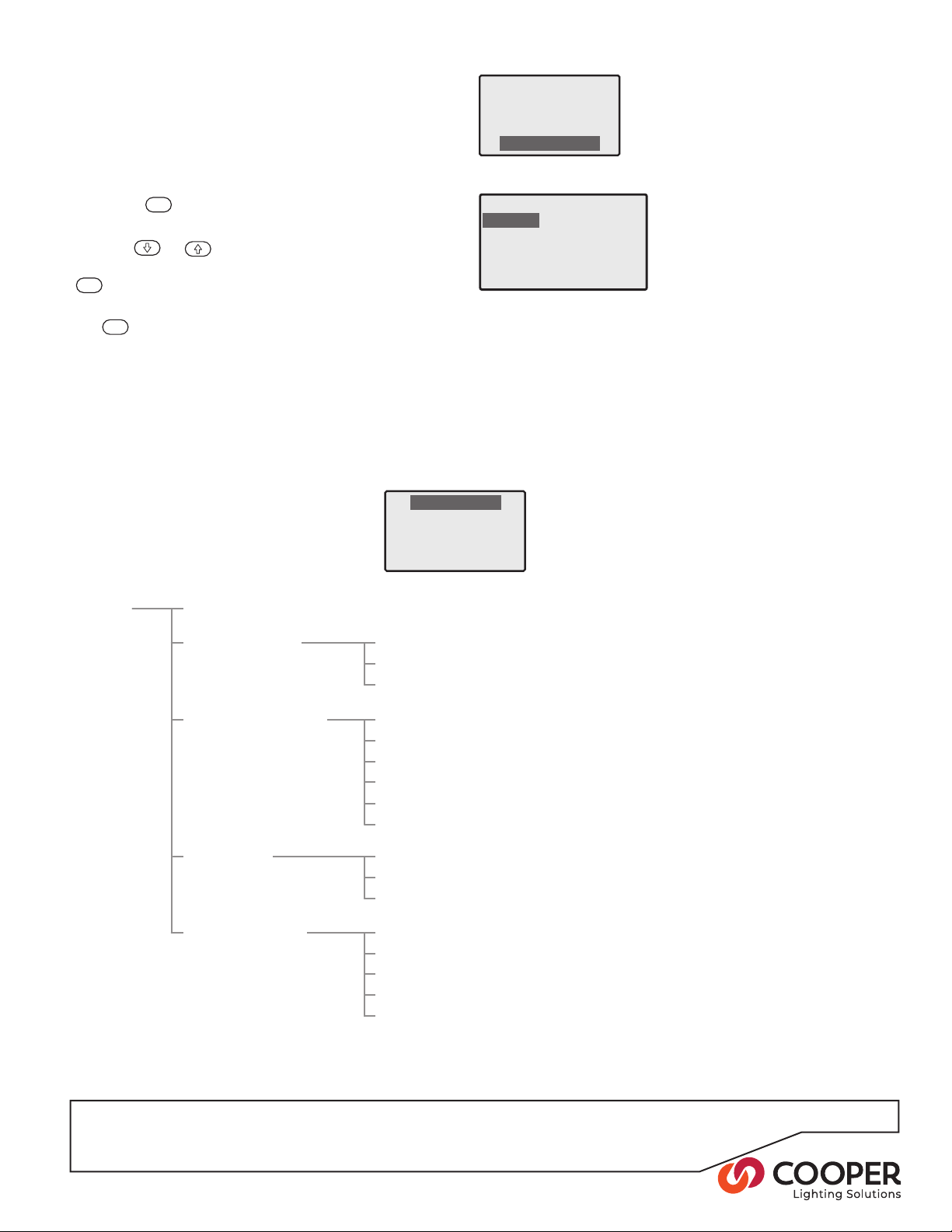
During normal operation, the control panel screen shows
only the time, date and device number
ð
To access the menus
1. Press the
Level menu
2. Use the
menu (Operation or Conguration) and then press the
button to select.
3. If requested, enter the four-digit password and press
the
Note: When the unit is supplied, there are initially no
passwords - see the section ‘Configuring passwords’.
4. If the password is accepted, the chosen menu will be
displayed.
button to display the Select Access
ð
or
button.
buttons to highlight the required
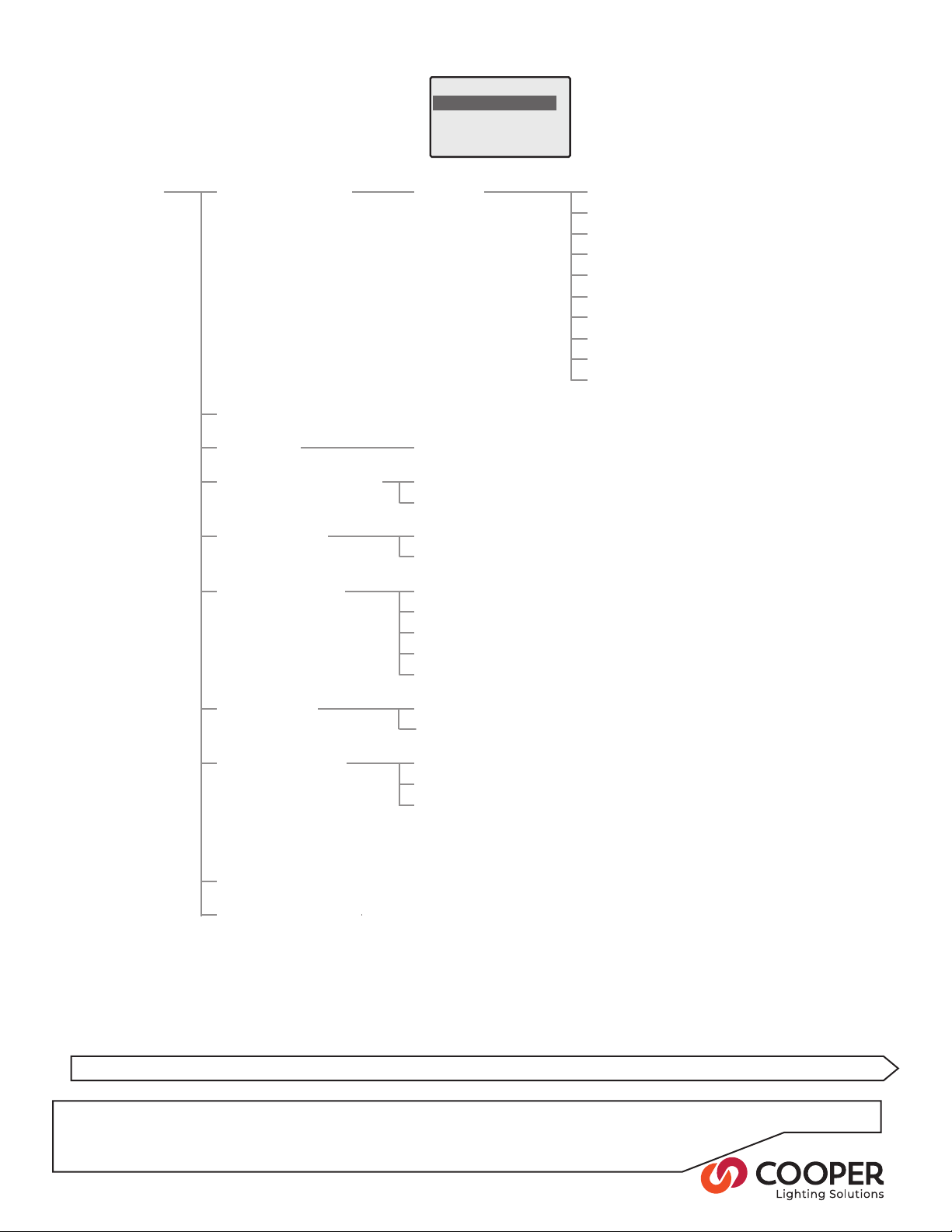
Menu Layouts
Operation menu layout
Cooper Lighting
Solutions
21:56
August 14, 2008
Select Access Level
Operation
Configuration
Contact Cooper
Lighting Solutions
Operation Help
Output Override All Outputs
Timeclock Manager Time & Date
Power Data Total Power see page 40
Communications iCANnet OFF/ON
see page 23 & 40
Each Output
Select Scene
see page 31
Events see page 33
Coordinates see page 31
Daylight Saving see page 32
Timestamp Frequency see page 32
Enable/Disable see page 30
Display by Phase
Display by Output
see page 41
Ethernet OFF/ON
DMX OFF/ON
RS485 OFF/ON
Contact Inputs OFF/ON
P9
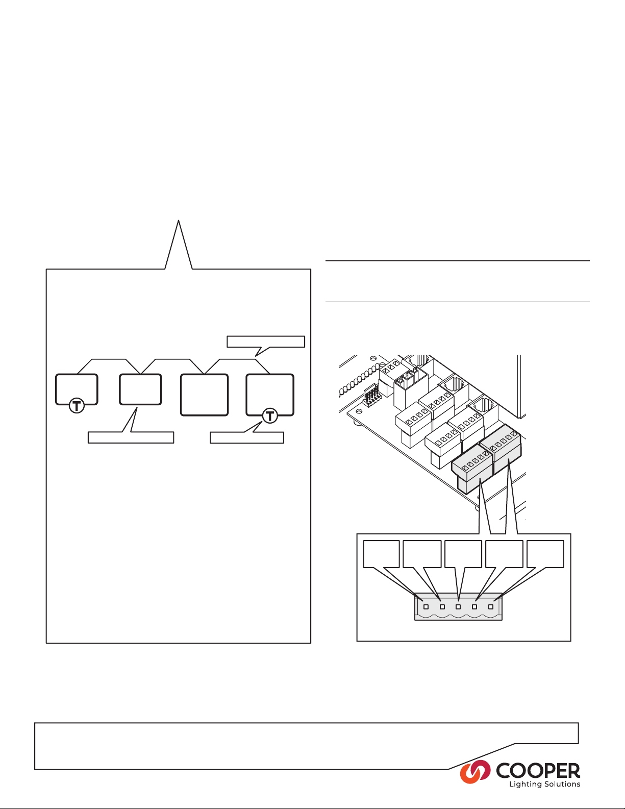
Page 10
Configuration Menu
Configure Outputs
Wallstation Wizard
Scene Edit
Emergency Scene Edit
Conguration menu layout
Conguration Congure Outputs Output x Standard Type see page 19
Set Area/Zone see page 20
Power Curve see page 20
HF Curve see page 20
Min/Max see page 21
Stabilization see page 21
Relay Zero Cross see page 21
Air-Gap Isolation see page 21
Operation at Min see page 21
Startup Action see page 21
Wallstation Wizard see page 28
Scene Edit Scene x see page 24
Emergency Scene Edit All Outputs
see page 25
Output x xx%
Contact Inputs Input 1
see page 26
Input 2
Ethernet Settings IP Addr
see page 35
IP Mask
Gateway
MAC
Restore Defaults
DMX Options Output Mapping
see page 36
Air-Gap Mode see page 36
Control Hierarchy iCAN Always see page 37
DMX Always
DMX When Present
Password Manager
see page 38
Restore Defaults Do Nothing see page 41
Dim:40% Switched:Off
Dim:40% Switched:On
P10
See page 11 for the list of commissioning steps
Page 11

Commissioning an Installation
This section presents the required steps for commissioning a new installation or modifying an
existing installation.
Commissioning Steps:
STEP ACTION PAGE
1: iCANnet control wiring 11
2: Power down the Source Controller, remove panels
and visually inspect all wiring and components 13
3: Power up the Source Controller 15
4: Energize each Output one at a time to determine
the location, type and current draw of its load 16
5: Congure Output behaviors 18
6: Remove the bypass jumpers on used Outputs 21
7: Covers the Source Controller and power the unit 21
8: Verify proper control of each Output using the
Output Override option 22
9: Congure Scene Values 23
10: Edit the Emergency Scene 24
11: Connect and congure contact inputs 25
12: Congure wallstations using the Wallstation Wizard 26
13: Verify each wallstation 28
14: Enable the timeclock 28
15: Congure the time, date, coordinates and
daylight saving time 29
16: Congure timeclock events 31
17: Congure Ethernet 33
18: Congure DMX 34
19: Congure passwords 36
Commissioning complete
P11
Page 12
Step 1: iCANnet control wiring
iCAN
+12V
(red)
CAN-H
(white)
DRAIN
(gray)
0V
(black)
CAN-L
(blue)
SC-UN
source
controller
SC-UN
source
controller
Wall-
station
Wall-
station
Objective: To identify the layout of the CAN network (also known as iCANnet) and connect the SC-UN Source
Controller (and other devices) to it. Verify the electrical characteristics of the network and terminate the end devices.
To identify the CAN network wiring layout
1. Use the installation plans to determine the layout of
the installed CAN network.
2. Determine where the SC-UN Source Controller(s) are
connected in the CAN network. In particular, identify
the devices that are located at either end of the CAN
network segment - these are the devices that must be
terminated.
General CAN network requirements
The CAN network requires devices to be linked together in a daisy-chain arrangement. A single run of
daisy-chained devices is called a Segment.
CAN network wiring
To wire all devices to the CAN network
1. Open the main panel door.
2. Remove the small access hatch cover located at the
base of the central panel by removing the four retaining screws.
3. If not already done, feed the CAN network cable(s) via
one of the four base knockouts through to the control
board area.
Note: There should be two CAN network cables un-
less the SC-UN Source Controller is at the end of the
network segment, in which case there will only be one
cable.
IMPORTANT: Keep all low voltage control wiring separate from high voltage power cabling to ensure safety
and noise immunity.
4. Connect the CAN network cable(s) to the iCAN
connector(s) on the control board according to the
following pin-outs:
Un-terminated device
Terminated device
There are three main constraints for a CAN network
segment:
• The combined cable lengths of the segment may
not exceed 3280 feet (1000 meters), and
• No more than 100 devices or nodes may be con-
nected within a single segment.
• Terminate the devices at each end of the segment
with a 120- ohm resistor. Leave the remaining
devices on the segment un-terminated.
Where more than 100 devices or excessive overall
cable lengths are required, it is necessary to use a
Bridge device to link two or more segments together.
Contact Cooper Lighting Solutions for details about
bridge devices.
5. Connect all other remaining devices to the CAN
network according to the installation plans and the
specic instructions for each device.
P12
Page 13
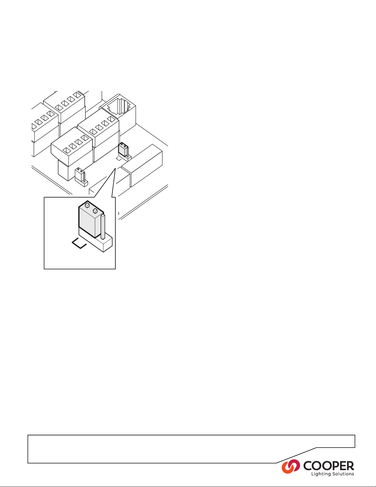
To terminate end devices
iCAN
TERM
iCAN
TERM
1. Locate the iCAN termination jumper on the control
board of the SC-UN Source Controller. It is next to one
of the two iCAN connectors.
2. Set the jumper according to the position of the SC-UN
Source Controller within the CAN network layout:
• If the SC-UN is one of the end devices, set the
jumper to the ‘iCAN TERM’ position.
• If the SC-UN is NOT one of the end devices in the
network, set the link to the other end of the jumper
block.
3. Check all remaining devices to ensure that only the
end devices are terminated.
Note: Some devices use jumper links (like the SCUN) for termination control, others require a 120 Ohm
resistor to be placed between the CAN-L and CAN-H
connections. Check the documentation for each device.
4. Replace the small access hatch cover and secure with
the four screws removed earlier.
P13
Page 14
Step 2: Visually inspect all wiring and components and Power up the Source
Controller
Objective: To verify proper wiring and mounting.
To ensure the Source Controller is powered
down
For SC-UN
1. Locate the main breaker that feeds the Source Controller.
2. Turn off the main breaker.
For SC-UN-FT
1. Locate the breaker that feeds the main power supply.
2. Turn off the power supply breaker.
3. Locate each breaker that feeds the dimmer cards.
4. Turn off each breaker that feeds the dimmer cards.
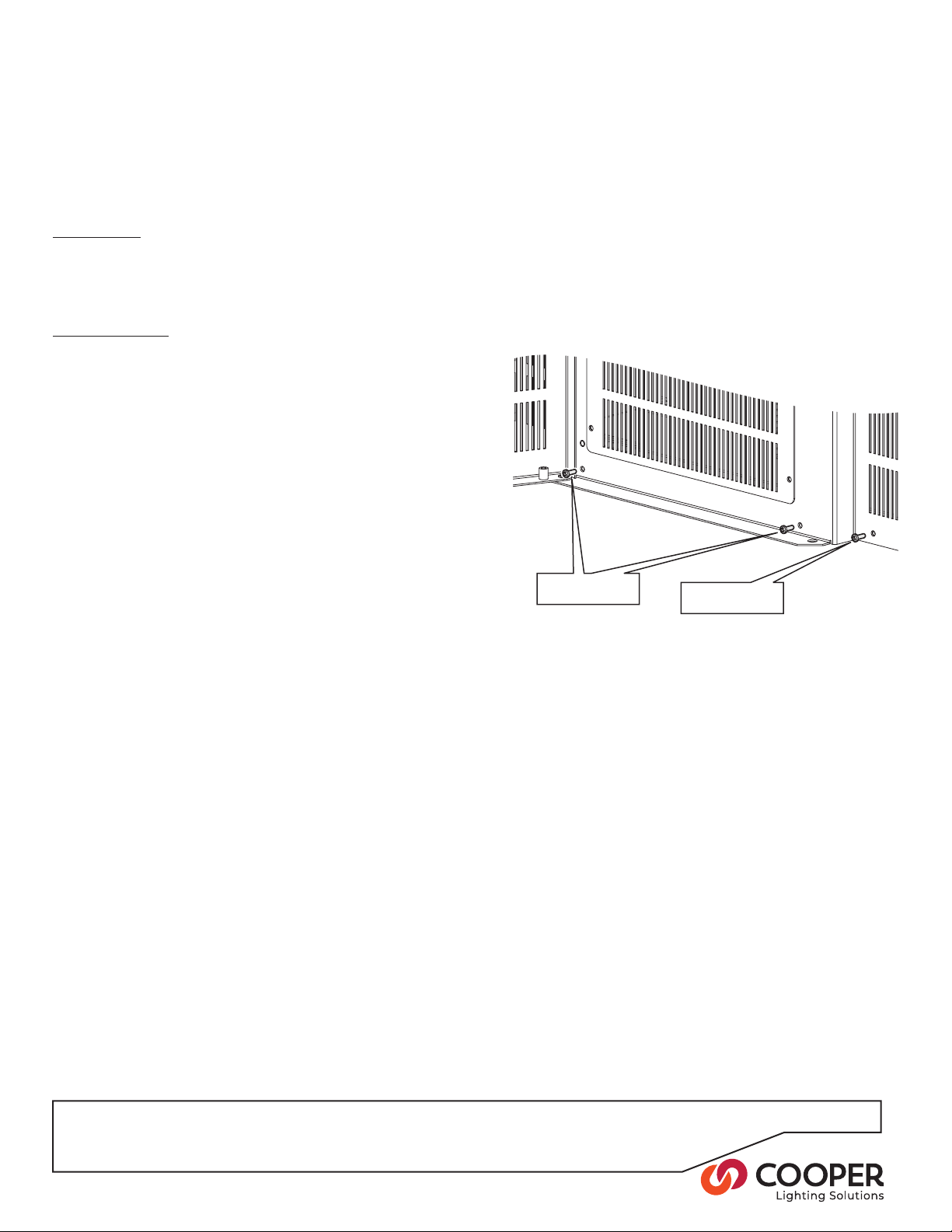
To remove the front panels
1. Open the main panel door.
2. Remove the two upper and two lower screws that
hold the central panel in place and carefully lift off the
complete panel.
3. Now remove the single upper and single lower screw
holding the right side panel in place. Carefully lift off
the panel.
Lower screws
for central panel
Lower screw for
right side panel
4. For 18 and 24 circuit models, repeat step 3 for the left
side panel.
P14
Page 15

SUPPLY
EARTH
HOT
NEUTRAL
SUPPLY
EARTH
NEUTRAL
PHASE 3
PHASE 2
PHASE 1
To inspect all wiring and components
Channels 1 to 12
Channels 13 to 24
Main power supply
wiring terminal
Main supply feed from circuit
breaker (Hot and Neutral Wires)
Dimmer Channel feed from circuit
breaker (Hot and Neutral Wires)
1. First check that the supply cabling safely enters via
the top central knockout and is correctly and securely
attached to the input contacts. Also check that the
insulation for each cable is fully intact up to the point
where it is stripped to enter the input contacts:
For SC-UN
Single phase units
For SC-UN-FT
2. Check that the load wiring has been correctly connect-
ed to each Output circuit and that each wire is fully
Three phase units
insulated to the point at which it enters the connector
block:
Bypass
jumper
Hot
(Live)
Maximum wire gauges
Solid wire: 10 AWG (6 mm2)
Stranded wire: 12 AWG (4 mm2)
Switched
Hot
Dimmed
Hot
Neutral
Inspect each Output circuit board for signs of any
damage to components during installation.
P15
Page 16

1
2
3
14
13
1 2 3 4 5 6
SUPPLY
3. Check that all load wires follow the vertical wireway(s)
1
2
3
4
5
6
7
18
17
16
15
14
13
SUPPLY
and exit through the appropriate knockouts into conduit and a wireway. Also check the earth links for each
load in the terminal(s) at the top of the cabinet.
4. Wherever possible check the wiring out to the lumi-
naires and also ensure that the total load on any single
circuit will not exceed 16 amps.
For SC-UN
Earth
terminal
For SC-UN-FT
Load
wiring
Vertical
wireways
Load
wiring
Earth
terminal
Step 3: Power up the Source Controller
Objective: To power up the Source Controller.
To Power up the Source Controller
For SC-UN
1. Locate the main breaker that feeds the Source Con-
troller.
2. If necessary, unlock the breaker from its off position.
3. Place the main breaker into its ON position.
4. Verify that the control panel on the unit is showing a lit
screen and one or more indicator lights.
For SC-UN-FT
1. Locate the breaker that feeds the Source Controller’s
power supply.
2. Place the breaker in the on position.
3. Verify that the control panel on the unit is showing a lit
screen and one or more indicator lights.
P16
Earth
terminal
Vertical
wireways
Earth
terminal
Page 17

Step 4: Energize each Output one at a time to determine the location, type and
(Orange)
Disconnect Lever
Hot
(Blue Terminal)
Neutral
(White Terminal)
As per Each Channel
0.14 tp 6mm
2
Max
26 to 10 Awg Max
current draw of its load.
Objective: To conrm the location, type and current of the loads attached to each Output, prior to removing the bypass
jumper.
To apply power to each Output and determine the location and type of the load
WARNING: Before applying power to any Output, check
that the associated load wiring and load(s) are in a
safe condition and are ready to be energized. With the
bypass jumper in place on the Output card, power will
be fed through to the load as soon as the breaker is
switched on.
For SC-UN
1. For a single Output, place the associated breaker into
the ON (Up) position to supply power to that Output.
2. Using the installation plans as a guide, walk around
the installation site and identify which luminaires have
been energized as a result of switching on the breaker.
Bypass jumper
3. Log a description of the luminaires against the Output
number. Also note the type of luminaires used as this
information will be needed when setting the Output
behaviors prior to removing the bypass jumpers.
4. Leave all unused breakers in the down (off) position.
WARNING: Before applying power to any Output, check
that the associated load wiring and load(s) are in a safe
condition and are ready to be energized. With the bypass
jumper in place on the Output card, power will be fed
through to the load as soon as the channel HOT screw
terminal is connected.
For SC-UN-FT
1. For each used Output, make certain that the orange
disconnect lever on the breaker wiring terminal block is
engaged across the hot terminal. Ensure that the bypass
jumper is still in place on the output card.
2. Locate the circuit breaker that feeds the rst dimmer out-
put.
3. Energize the circuit breaker.
4. Using the installation plans as a guide, walk around the
installation site and identify which luminaires have been
energized as a result of switching on the breaker.
5. Log the breaker panel and circuit number that feeds each
Output. Log a description of the luminaires against the
Output number. Also note the type of luminaires used as
this information will be needed when setting the Output
behaviors prior to removing the bypass jumpers
P17
Bypass jumper
Page 18

Step 4 (continued)
1 2 3 4 5 6
13 14 15 16 17 18
19 20 21 22 23 24
7 8 9 10 11 12
ESC
12
0
ENT
3
456
789
#
20
20
20
20
20
20
20
Measure the current draw of the load
For SC-UN
1. For the Output that is currently energized, locate the
live wire that exits from the base of the breaker.
2. Carefully place a clamp meter around the wire and
read the current. If the reading exceeds 16 amps then
you must not proceed any further with this circuit. There
may be a short circuit or the load is too large. Check all
wiring and each luminaire. If necessary, consider split-
ting the load across more than one Output.
Clamp
here
3. Repeat all of the steps within Step 4 for the next
Output that has a load wired to it. When all Outputs
have been checked in this way, go to ‘Step 5: Congure Output behaviors’.
P18
Page 19

For SC-UN-FT
1. For the Output that is currently energized, locate the
live wire that exits the HOT terminal block.
2. Carefully place a clamp meter around the wire and
read the current. If the reading exceeds 16 amps then
you must not proceed any further with this circuit. There
may be a short circuit or the load is too large. Check all
wiring and each luminaire. If necessary, consider split-
ting the load across more than one Output.
3. Repeat all of the steps within Step 4 for the next
Output that has a load wired to it. When all Outputs
have been checked in this way, go to ‘Step 5: Congure Output behaviors’.
Clamp
here
P19
Page 20

ENT
ENT
Configure Output 1
Standard Type
Set Area and Zone
PowerCurve (Square)
HF Curve(Switched)
Power curve: Square
HF curve: Switched
Min5%Max 90%
<>for more
Output 1
ENT
Output1Standard Type
Incandescent/MLV
Non-Dim Source
Electronic Low Voltage
0-10VDriver/Ballast
ENT
ESC
ESC
Power curve: Square
HF curve: Switched
Min5%Max 90%
<>for more
Output 1
Area 32
Zone 256
<>for more
Output 1
+ST+ZC +FLMoff
Step 5: Congure Output behaviors
Objective: To congure each Output to properly control the connected load type.
To congure the behavior of an Output
1. From the Conguration menu, highlight the ‘Congure
Outputs’ option and press the
button. The display
will show a summary of the settings for the rst output:
Output number
- use &
to change
Existing Power and
HF (low voltage) curve
settings
Existing Area
and
Zone settings
2. Use the
3. Press the
or
buttons to navigate the Outputs.
button to edit details for the current
Output number:
4. Highlight the ‘Standard Type‘ option and press the
button. The list of standard lighting loads will be
displayed:
5. Highlight the type that most closely matches the load
connected to the Output and press the
button.
Once selected, all basic parameters will be set for the
load (as summarized right) and you will be returned to
the ‘Congure Output x’ menu. Other options can be
changed here, however, for most standard installations
no further changes are required. See the next two
pages for details about all of the available options in
the Congure Output menu.
Note: The ‘Set Area and Zone’ option allows you to
assign the chosen Output to a particular Area and
Zone - these operations can also be performed later
using the iCANsoft application.
6. Press the
button to return to the summary of set-
tings for the Output. From here, either:
• Select another Output number using the
or
buttons, or
• Press the
button to return to the Conguration
menu.
Existing
Minimum
and Maximum
power
dimming limits
Load Type Power Curve HF Curve Min Max
Incandescent/MLV Square Law 0-10V 0 90
Non-dim source Switched Switched 0 100 û ü
Electronic Low Volt. Square Law 0-10V 5 90 ü ü
0-10V driver/ballast Switched 0-10V 0 100 û ü
1-10V driver/ballast Switched 1-10V 0 100
3-wire fluorescent Square Law 0-10V 20 90 û ü
2-wire fluorescent Square Law 0-10V 12 100 ü ü
Neon Square Law 0-10V 20 90 ü ü
Status indicators:
+ST is displayed when ‘Stabilization’ is enabled
+ZC is displayed when ‘Zero-Cross’ is enabled
+FL is displayed when ‘Relay Follow’ is enabled
Moff or Mon depending on ‘Operation at Min’ set.
Stabilization
Operation at Min
Off
ü
ü
Off
Off
Off
ü
Off
û
Off
Off
Off
Relay Zero Cross
Air-Gap Isolation
ü
ü
ü
ü
ü
ü
ü
ü
When all Outputs are congured, go to Step 6
P20
Page 21

Configure Output 1
Standard Type
Set Area and Zone
Min/Max (0/100)
RelayZero Cross *
OperationatMin (Off)
Power Curve(Square)
Stabilization
Air-Gap Isolation *
StartupAction (Last sc)
0%
0% 10% 20% 30% 40% 50% 60% 70% 80% 90% 100%
10%
20%
30%
40%
50%
60%
Actual power output
Dimming level requested
70%
80%
90%
100%
Options when conguring Output behaviors
There are various options available to congure the
behaviors of each Output to suit their connected loads.
These pages summarize all of the options.
Standard Type
Use this option to quickly congure all of the default
settings for a particular type of load connected to an
Output. The various default settings are summarized
below:
Once the standard type settings are in place for the
Output, you can then optionally visit the other options
separately to adjust the conguration if required.
Set Zone/Area
This option allows you to assign the Output to a Zone
and Area number, without the need to use the iCANsoft application. The Zone number will be used to
identify the Output across the iCANnet network.
Power Curve
This option determines the relationship between the
requested dimmer level and the actual power level
supplied to the load. There are three options to cover
the various load types that can be controlled.
• Linear produces a like-for-like response, i.e. 40%
level requested, 40% power level supplied.
Linear
response
curve
Square Law
response
curve
• Square Law modies the relationship to account for
how the human eye adapts to reduced light levels.
The above graph reects the difference between the
linear and square law power response curves.
• Switched is either fully on or fully off. Any dimming
level request above zero will cause full power to be
instantly supplied.
P21
HF Curve
This option denes the relationship of the low voltage
(0-10V) Output to the dimmer level. The ranges that
can be selected are: 1-10V, 0-10V, 10-1V, 10-0V.
Page 22

Min/Max
Allows you to dene the minimum and/or maximum
dimming levels. This option is used primarily when
loads of certain types are used, such as neons, which
become unstable at extremely low dimming levels.
Both settings are expressed as percentages of the
total standard dimming range. When the range of an
Output is congured in this way, its reduced dimming
range will be scaled to t within the normal 0 to 100%
dimming instructions received from wallstations and
other controllers.
Stabilization
This option invokes a system that lters uctuations in
the main power source to maintain a consistent true
voltage level to the connected load.
Relay Zero-Cross
When this option is set to ‘Switch at 0 Volts’, the opening and closing of the relay will be synchronized with
the zero-crossing point of the sine wave in order to
protect the relay contacts from arc damage.
In most instances, you should leave this option enabled.
Operation at Min
This option determines what the Output should do
when the chosen Minimum level is reached.
When this option is set to ‘Turn Off’, the Output will
switch off when the corresponding minimum level is
reached.
When this option is set to ‘Stay at Min’, the Output will
remain at the corresponding minimum level.
Startup Action
This option determines how the selected Output
should recover from a power failure once the supply is
restored. There are three settings available:
• Restore Last Scene reinstates the scene that was
being displayed when the power outage occurred.
• Use Emergency Scene will display the scene that
is dened within the ‘Conguration’ > ‘Emergency
Scene Edit’ option.
• Select Scene allows you to assign any standard
scene numbered up to 128. When you select this
setting, a sub page will request the scene number.
Air-Gap Isolation
This option relates to the operation of the relay which
is used within each output to ensure full ‘air gap’ load
isolation when the dimming level is at zero.
When this option is set to ‘Open at 0%’, the relay will
isolate the circuit when the dimming level reaches
zero.
When this option is set to ‘Disabled’, the relay will
maintain contact continually and will not isolate the
circuit at any time.
P22
Page 23

Step 6: Remove the bypass jumpers on
used Outputs.
Step 7: Cover the Source Controller and
power the unit
Objective: To release each active Output circuit so that
dimming control becomes possible.
To remove the bypass jumper
For SC-UN
1. Locate the main breaker that feeds the Source Controller. Turn off the main breaker.
2. If they are not already taken off, remove the front pan-
els from the Source Controller. See step 2 for details.
3. Carefully remove the bypass jumper from the Output
board. Insert the tip of a atblade screwdriver at the
indentation by the intersection of the terminal block
and jumper and twist the atblade to remove the
jumper.
4. Repeat step 3 (above) for all other active Output cir-
cuits.
5. Replace the front panels onto the Source Controller.
See Step 7 for details.
For SC-UN-FT
1. Locate the breaker that feeds the main power supply.
Turn off the power supply breaker.
2. If they are not already off, locate each breaker that
feeds the dimmer cards. Turn off each breaker that
feeds the dimmer cards.
3. If they are not already taken off, remove the front panels from the Source Controller. See step 2 for details.
4. Carefully remove the bypass jumper from the Output
board. Insert the tip of a atblade screwdriver at the
indentation by the intersection of the terminal block
and jumper and twist the atblade to remove the
jumper.
5. Repeat step 4 (above) for all other active Output cir-
cuits.
Objective: To make safe the Source Controller and apply
power to it.
To replace the front panels
1. Replace the side panel(s) rst. Place the right side panel
onto the chassis and replace the upper and lower xing
screws.
2. For 18 and 24 circuit models, repeat step 1 for the left
side panel.
3. Place the central panel onto the chassis and open the
door. Replace the two upper and two lower xing screws.
Lower screws
for central panel
Lower screw for
right side panel
To Power up the Source Controller
For SC-UN
1. Locate the main breaker that feeds the Source Controller.
2. If necessary, unlock the breaker from its off position.
3. Place the main breaker into its ON position.
4. Verify that the control panel on the unit is showing a lit
screen and one or more indicator lights.
P23
For SC-UN-FT
1. Locate the breaker that feeds the Source Controller’s
power supply. Place the breaker in the on position.
2. Locate the breakers that feed the dimmer Outputs.
Place the breakers in the on position.
3. Verify that the control panel on the unit is showing a lit
screen and one or more indicator lights.6. Replace the
front panels onto the Source Controller. See Step 7 for
details.
Page 24

ENT
ENT
ENT
Override-Options
All Outputs
Each Output
Select Scene
Override: Each Output
Output1 0%
Output2 0%
Output3 0%
Output4 0%
Step 8: Verify proper control of each Output using the Output Override option
Help
OutputOverride
TimeclockManager
PowerData
OperationMenu
Override - Options
AllOutputs
Each Output
Select Scene
Objective: To prove that each Output can be controlled by dimming commands.
To use the Output Override option
1. From the Operation menu, highlight the ‘Output Over-
ride’ option and press the
show the available options:
button. The display will
2. Use the
Output’ option and press the
3. Use the
or
buttons to highlight the ‘Each
button.
or
buttons to highlight each Output
sequentially and then, either:
• Use the
or
buttons to decrease or increase
the dimming level, or
• Use the numeric keypad to enter a dimming level
from 0 to 100% and then press the
button to
set the Output to the selected level.
4. Check that the load responds as expected and then
return the dimming level to zero using either of the
above two methods.
5. Repeat Steps 3 & 4 for each Output. If the loads do
not respond correctly, verify the output programming
from Step 5 on Page 18.
P24
Page 25

ENT
ENT
ESC
ENT
ENT
Scene config: Scene
Scene 1 (empty)
Scene 2 (empty)
Scene 3 (empty)
Scene 4 (empty)
Scene1Levels
Output 1 10%
Output 2 50% SM
Output 3 Ignore
Output 4 Ignore
ENT
ENT
ENT
ESC
Override-Options
All Outputs
Each Output
Select Scene
Override: Select Scene
Select Scene
1
Step 9: Congure Scene Values
Override - Options
AllOutputs
Each Output
Select Scene
Override - Options
AllOutputs
Each Output
Select Scene
Objective: Congure the Scene value for each Output.
To set local Scene Value
1. From the Conguration menu, highlight the ‘Scene
Edit’ option and press the
show a list of Scene numbers ranging from 1 to 128:
2. Use the
or
buttons to highlight the required
Scene number and press the
will show a list of the Outputs contained within the
Source Controller and their dimming levels within the
scene.
3. Use the
or
buttons to highlight the required
Output number and then change its value in any of the
following ways:
• Press the
or
crease the dimming level,
• Use the numeric keypad to directly enter the required dimming level, from 0 to 100% and press the
button to set the Output to the selected level.
• Press the
button to change between the dimming level, the dimming level with an ‘SM’ (Scene
Modify) sufx and the ‘Ignore’ option.
During normal operation, Scene Modify commands
may be issued by a controller on the iCANnet
network or from the ‘Events’ section within the
Source Controller. Any Outputs that are marked with
‘SM’ in the Scene will be adjusted (in proportion)
by a stated amount from their normal Scene
levels. Outputs without the ‘SM’ sufx will remain
unaffected by any Scene Modify commands.
Outputs congured to ‘Ignore’ a Scene selection will
remain uncharged at their previous state whenever
this Scene is selected.
4. Repeat step 3. for all other Outputs, as necessary.
5. To save all changes press the
return to the previous screen, press the
button. The display will
button. The display
buttons to decrease or in-
button. To exit and
button.
To select a Scene
1. From the Operation menu, highlight the ‘Output Over-
ride’ option and press the
button. The display will
show the available options:
2. Use the
Scene’ option and press the
or
buttons to highlight the ‘Select
button.
3. Choose the required Scene number in either of two
ways:
• Press the
or
buttons to decrease or in-
crease the required Scene number.
• Use the numeric keypad to directly enter the re-
quired Scene number and press the
button to
select the scene.
4. To exit, press the
button to return to the previous
screen.
P25
Page 26

ENT
ENT
ENT
ESC
Emergency Scene
All Outputs
Output190%
Output290%
Output390%
Step 10: Edit the Emergency Scene
Objective: To congure the desired Output levels for the Emergency Scene.
The Emergency Scene is pre-congured to set all Output levels to 100%. If you do not need to edit the Emergency
Scene as part of your commissioning process, then go straight to Step 11.
To edit the Emergency Scene
1. From the Conguration menu, highlight the ‘Emer-
gency Scene Edit’ option and press the
button.
The display will show a list of the congured Output
settings:
2. You can alter Output levels collectively or individually,
as required:
Collectively - Highlight the ‘All Outputs’ option and ei-
ther type the required dimming level using the keypad
or use the
or
value for all Outputs and press the
buttons to adjust the current
button.
Individually - Highlight the required Output and either
type the required dimming level using the keypad or
use the
or
and press the
3. To exit, press the
buttons to adjust the current value
button to set the Output value.
button to save all changes and
return to the previous screen.
What is the Emergency Scene?
The Emergency Scene is a group of settings for one
or more Outputs that will only be used in cases of
emergency, generally to provide evacuation lighting.
The Emergency Scene can be invoked in any of four
ways:
• When a Contact Closure Input places the Source
Controller into the Emergency State (a condition
where most CAN messages are ignored and the
Emergency Scene is displayed until such time
that the Emergency State is cancelled).
• During the restoration of the supply following a
power outage (dependant on the setting within
the Congure Outputs Startup Action option -
see page 20).
• By using the ‘Operation’ > ‘Output Override’ >
‘Select Scene’ option and selecting Scene 132.
• On receipt of an iCANnet Emergency message.
P26
Page 27

Step 11: Connect and Congure Contact Inputs
ENT
Contact Inputs
Input 1
Open:DoNothing
Close: Do Nothing
Input 1: Open
Do Nothing
Enter Emergency State
Exit Emergency State
Select Scene 1
Contact Inputs
Select Scene
1
ENT
Contact
closure
Switch
input 1
Switch
input 2
ENT
ENT
Objective: To connect and congure the volt-free inputs that allow event triggers from devices and other building
systems to invoke appropriate reactions from the Source Controller.
To connect contact inputs
1. Access the control board located at the base of the
SC-UN cabinet, as discussed in Step 1.
2. Connect the input wires from the external system to
either switch input 1 or switch input 2 of the Contact
Closure connector.
To congure contact inputs
1. From the Conguration menu, highlight the ‘Contact
Inputs’ option and press the
will show the current settings for the rst input:
button. The display
Action activated when
the contact input opens
will enter the special Emergency State. While in
this state, the dimming levels congured for the
Emergency Scene will be used and the unit will not
respond to most iCAN messages until the Emergency State is cancelled. The Emergency State can
be cancelled either upon receipt of a special iCAN
message or by using the ‘Exit Emergency State’ on
the opposing contact input condition.
• Exit Emergency State When the contact input con-
dition becomes true, the Emergency State will be
cancelled, all iCAN messages will be accepted and
normal operation will resume with the scene last
displayed before the Emergency State.
• Select Scene xxx When the contact input condition
becomes true, the outputs of the Source Controller will change to those dened within the selected
scene number. When this setting is chosen and you
press the
button, a second screen will prompt
you to enter a scene number:
Action activated when
the contact input closes
2. Use the
or
buttons to highlight the required
contact input condition (‘Open’ or ‘Close’) and press
the
button. The display will show the actions that
are available for the chosen contact input condition:
• Do Nothing The Source Controller will ignore the
input state.
• Enter Emergency State When the contact input
condition becomes true, the Source Controller
Note: The input from the external system should just
provide a volt free contact between the two input
terminals when it is active; it should not introduce any
external voltage onto either wire.
Enter the appropriate scene number and press the
button.
3. Repeat step 2. for the alternate condition within the
same contact input. For instance, if the ‘Close’ contact
input condition is set to ‘Enter Emergency State’, then
the corresponding ‘Open’ condition should be set to
‘Exit Emergency State’ in order to return the Source
Controller back to normal operation.
4. If necessary, congure the other contact input by using
either the
button to scroll up to ‘Input 1’.
button to scroll down to ‘Input 2’ or the
P27
Page 28

Step 12: Congure wallstations using the Wallstation Wizard
Wallstation Wizard
Please identify
Wallstations
ENT
ENT
ENT
Select Wallstation
1 Ineo6scsmall
WS1Style 10
CLS-2-TSB-RL
CLS-4-TSB
CLS-4-TSB-RL
CLS-6-TSB
ENT
ENT
WS1Set Up
Quick SetUp
Advanced
ENT
WS1SelectTemplate
176scsmall
WS 1Parameters
Select an Area for
the Wallstation
1
WS 1Parameters
SelectaScene number
for the first button
1
WS 1Parameters
Selectacommon
Scene fade time
1.3 sec
ENT
ENT
ESC
ENT
Objective: Use the Wallstation Wizard to quickly locate
wallstations and program them directly from the SC-UN
control panel. If you do not need to congure wallstations
as part of your commissioning process, then go straight to
Step 13.
4. The screen will now allow you to choose between the
To use the Wallstation Wizard
1. From the Conguration menu, highlight the ‘Wallstation
Wizard’ option and press the
will request you to identify:
2. Go to each wallstation and prompt each one in turn
to send out an ‘announcement’ message over the
iCANnet network. The Wallstation Wizard will listen for
announcements and will add any response to its list of
devices.
Note: The various models of wallstations each have their
own method to cause an announcement message. Please
see Appendix 1 of this guide for more information.
When the rst announcement message is received, the
Wallstation Wizard will list the device:
button. The display
‘Quick Set Up’ or ‘Advanced’ methods:
• Quick Set Up creates standard settings for the
whole wallstation based upon just three details that
you provide.
• Advanced allows you to program each button individually.
Highlight the required mode and press the
ton.
5. Use the chosen mode to program the wallstation:
Quick Set Up
a. In Quick Set Up, your rst action is to choose the pro-
gramming template to be used:
In many cases there may just be one template, however,
some wallstations may provide a choice. If so, highlight
the appropriate template and press the
but-
button.
3. Press the
button to select the highlighted device.
The screen will now show the expected style for the
wallstation. This relates to the button layout, of which
there can be many for each type of wallstation. You
may need to check the details of the wallstation to
discover its exact style options.
• If the button layout style is correct, press the
ton to choose the highlighted ‘OK’ option - go to step 4.
• If the button layout style does not match the wallstation,
move the highlight to the ‘Change’ option and press the
button. Each wallstation contains a style number.
Select the style that matches the style number printed
on the wallstation. The available styles will be listed:
Move the highlight to the desired style and press the
button to select. The Select Template screen
will be displayed - go to step 5.
but-
b. You will be asked for three parameters: An Area number,
an initial Scene number and a common fade time:
Use the keypad to enter the rst two items, and the
and
buttons to adjust the fade time. The buttons will all be programmed with the same Area and
Fade details and increment Scene numbers from your
initial Scene parameter.
Advanced
a. The initial advanced screen will show all of the but-
tons. Highlight a button and press the
button.
b. You can now adjust the Area, Scene and Fade details
for the chosen button. Use either the keypad (not for
fade) or the
and then press the
and
buttons to adjust each entry
button to send your changes to
the wallstation and return to the main advanced screen.
c. When you have nished programming the buttons, press
the
button to return to the ‘Select Wallstation’ screen.
P28
Page 29

WS1Style 10
CLS-6-TSB
OK
Change
WS1 Select Template
176scsmall
WS1Configuration
Configuring
Wallstation
WS 1Config buttons
Scene button 1
Scene button 2
Scene button 3
Scene button 4
WS1Style 10
CLS-2-TSB-RL
CLS-4-TSB
CLS-4-TSB-RL
CLS-6-TSB
WS 1Parameters
Select an Area for
the Wallstation
1
WS 1Parameters
SelectaScene number
for the first button
1
WS 1Parameters
Selectacommon
Scene fade time
1.3 sec
WS 1 Scene button1
Action: Select Scene
Area: 1
Scene: 1
Fade: 1.2 sec
1
WS 1 Scene button1
Action: Select Scene
Area: 1
Scene: 1
Fade: 1.2 sec
1
WS 1 Scene button1
Action: Select Scene
Area: 1
Scene: 1
Fade: 1.2 sec
1.2 sec
Select Wallstation
1 Ineo6scsmall
Wallstation Wizard
Please identify
Wallstations
WS1Set Up
Quick Set Up
Advanced
Wallstation
announce
ENT
ENT
ENT
ENT ENT
ENT
ENT
ENT
ENT
ENT
ENT
ENT
ENT
ENT
ESC
Quick Set Up
section
Advanced
section
Wallstation Wizard Layout
The diagram summarizes the
general layout and navigation of
the various screens within the
wizard.
Each entry will be marked
with an asterisk once it
has been congured via
the Wallstation Wizard.
P29
Page 30

Step 13: Verify each Wallstation
Timeclock Manager
Timeclock
Enabled
Disabled
*
ENT
ENT
ENT
ESC
Step 14: Enable the Timeclock
Objective: To conrm the conguration of each
wallstation.
To verify a wallstation
1. Go to the wallstation and, in turn, press the buttons
that are known to have been programmed to select
Scenes.
2. Check that the response of the controlled lighting circuits to each button press match what is expected.
3. Repeat steps 1. to 3. for each wallstation.
4. Press the buttons on each wallstation to verify their
operation. If the lights do not respond as expected,
check the Wallstation programming (Step 12), the
Scene Output Values (Step 9), or the Output Area Settings (Step 5).
Objective: Enable the timeclock on one SC-UN Source
Controller.
Note: We recommend using only one Source Controller
Timeclock to control all of the devices on a Segment.
To enable the timeclock
1. From the Operation menu, highlight the ‘Timeclock
Manager’ option and press the
2. Use the
or
buttons to highlight the ‘Enable/
Disable’ option and press the
will show the timeclock options with the currently active setting marked with an asterisk:
3. Use the
or
setting and press the
buttons to highlight the desired
button. The chosen
setting will be saved and the display will return to the
Timeclock Manager menu.
To exit without saving any changes, press the
button.
Note: When the timeclock feature is enabled, the will
illuminate in red.
button.
button. The display
P30
Page 31

ENT
Timeclock Manager
Time&Date
Events
Coordinates
Daylight Saving
ENT
ENT
Timeclock Manager
Time&Date
23:0123
21 Aug 2008
ENT
Step 15: Congure the Time, Date, Coordinates and Daylight Saving Time
ENT
ESC
Timeclock Manager
Time&Date
Events
Coordinates
Daylight Saving
Select State
GA: GEORGIA
HI: HAWAII
FL: FLORIDA
ID: IDAHO
Coordinates
Set by City
Set Manually
ENT
ENT
ENT
Select City
Atlanta
Augusta
Athens
Brunswick
Coordinates
North America
Canada
Coordinates
Latitude +33.75
Longitude+84.40
Timezone GMT-5h
Objective: To ensure that the Source Controller has the correct time and location related settings.
To set the time and date
1. From the Operation menu, highlight the ‘Timeclock
Manager’ option and press the
play will show the available options:
2. Highlight the ‘Time & Date’ option and press the
button. The display will show the current time and
date:
3. Use the
or
buttons to move the highlight
between the items: hour, minute, day, month or year.
Use the
or
buttons to change the highlighted
item, as required.
4. When all items have been updated, press the
button to save and exit.
To exit without saving your changes, press the
button.
button. The dis-
To set the location and time zone
Note: Location and time zone information can also be edited
from within the iCANsoft application.
1. From the Operation menu, highlight the ‘Timeclock
Manager’ option and press the
play will show the available options:
2. Use the
or
buttons to highlight the
‘Coordinates’ option and press the
display will give you the options to ‘Set by City’ or ‘Set
Manually’.
To ‘Set by City’
1. Use the
or
buttons to highlight the “Set by
City’ option and press the
show you the available options:
button. The dis-
button. The
button. The display will
2. Highlight your Country of choice and press the
button. The display will show the available States.
3. Use the
city press the
or
buttons to highlight the closest
button.
The Latitude, Logitude, and Time Zone coordinates will
automatically update based on your city selection and
will show on the display for approximately 3 seconds.
P31
Page 32

ENT
ENT
ENT
ENT
ESC
ENT
Daylight Saving
Start 09 March
End 02 November
DST Rules: USA
ENT
ENT
Edit Timestamp
Off
Once per Minute
Once per Hour
*
Once per Day
Timeclock Manager
Time&Date
Events
Coordinates
Daylight Saving
TimeclockManager
Coordinates
Daylight Saving
Timestamp Frequency
Enable/Disable
ENT
ESC
Step 15 (continued)
ENT
ENT
ESC
ENT
ESC
ENT
Coordinates
Set by City
Set Manually
Edit Coordinates
Latitude +44.27
Longitude+65.20
Timezone GMT+0h
To ‘Set Manually’
1. Use the
or
Manually’ option and press the
buttons to highlight the “Set
button..
The display will display the ‘Edit Coordinates’ screen.
2. Use the
or
buttons to move the highlight
between the items: Latitude, Longitude and Time
zone.
3. Press the
button to enter the edit screen for the
highlighted item:
• Use the
or
buttons to increment/decre-
ment the current value.
• Use the numeric keypad to directly enter the new
value.
• Press the
• Press the
button to save and exit.
button to exit without saving.
4. Repeat steps 2. and 3. for each entry and when all
items have been updated, press the
button to
save and exit.
To exit without saving your changes, press the
button.
3. Press the
button to begin editing, whereupon the
highlight will appear on the ‘Start’ entry.
Note: The ‘DST Rules’ option has the following settings: ‘Man-
ual’, ‘Disabled’, ‘EEC’, ‘Europe’ and ‘USA’. Changes to the
‘Start’ and ‘End’ date options will only be accepted if ‘DST
Rules’ is set to ‘Manual’.
To prevent any automatic time shifting from occurring,
change the ‘DST Rules’ option to ‘Disabled’.
• Use the
or
buttons to move the highlight
between the items.
• Use the
or
buttons to increment/
decrement the current value.
• Press the
• Press the
button to save and cease editing.
button to cease editing without
saving.
4. Repeat step 3. for each entry and when all items have
been updated, press the
button a second time to
exit from the screen.
To set the timestamp frequency
The Timestamp Frequency determines how often a time
synchronization message should be sent across the iCAN
network in order to update any other units.
1. From the Operation menu, highlight the ‘Timeclock
Manager’ option and press the
play will show the available options:
2. Use the
or
buttons to highlight the
button. The dis-
To set daylight saving
The daylight saving time setting allows the Source Con-
troller to automatically adjust itself for the annual one hour
time shift every spring and fall.
1. From the Operation menu, highlight the ‘Timeclock
Manager’ option and press the
play will show the available options:
2. Use the
Saving’ option and press the
will show the current daylight saving time settings:
P32
or
button. The dis-
buttons to highlight the ‘Daylight
button. The display
‘Timestamp Frequency’ option and press the
button. The display will show the full range of
timestamp frequency options with the currently active
setting marked with an asterisk:
3. Use the
or
setting and press the
buttons to highlight the required
button. The chosen
setting will be saved and the display will return to the
Timeclock Manager menu.
To exit without saving any changes, press the
button.
Page 33

Step 16: Congure Timeclock Events
ENT
ENT
ENT
ESC
ENT
ENT
Event 001
Type Astro
Repeat Daily
01:00 Before Dawn
Action Select Scene
ENT
Timeclock Manager
Time&Date
Events
Coordinates
Daylight Saving
Event 001
Disabled
ENT
Objective: To congure automated events based either upon xed times or variable occurrences such as dawn
and dusk relative to the global location of the installation.
To view, create and edit timeclock events
1. From the Operation menu, highlight the ‘Timeclock
Manager’ option and press the
play will show the available options:
2. Use the
or
option and press the
buttons to highlight the ‘Events’
button. The display will show
the status of Event 001. If the rst event is disabled,
you will see:
To activate it, press the
button twice and change the
Event Type setting from ‘Disabled’ to either ‘Time’ or ‘Astro’.
If the rst event is not disabled, you will see a sum-
mary of its settings:
Type of timing:
Absolute (‘Time’) or
Astronomical (‘Astro’)
button. The dis-
Event number:
Use & to change
4. Press the
button to begin editing the required
event number. The highlight will move to the rst op-
tion within the summary screen. You can now:
• Use the
or
buttons to move the highlight
between the options.
• Press the
button to change the setting of the
currently highlighted option:
◊ Within an option, use the
or
buttons to
move the highlight to the required setting and
then press the
◊ Alternatively, press the
button to select it.
button to exit from
the list of settings without changing the setting.
◊ Where the option is numerical, i.e. the time set-
ting, use the
value, the
light and the
or
or
buttons to change each
buttons to move the high-
button to save your changes
and return to the summary screen.
A listing of all options available within this section is
shown on the next page.
Frequency of
repetition
Time or Astronomical
event and offset
Event action
3. Use the
or
buttons to change the event
number - between 001 and 255. As each event
number is selected, the display will either show a
summary screen of the existing settings or will show
‘Disabled’.
P33
Page 34

Step 16 (continued)
Event options
Type
This option determines whether the event should be
based on an absolute time (‘Time’) or a variable occurrence (‘Astro’) such as dawn or dusk. A ‘Disabled’
setting allows you to make the current event inactive.
Repeat
Exact Time - Begins the selected action only at a
specied time, day, month and year.
Daily - Begins the selected action at the specied time
every day.
Specic Days - Begins the selected action at the
specied time on every day that is chosen within this
option. When you rst choose this option, the screen
will show: ‘No days selected’. Press the numeric buttons between 1 and 7 (button 1 = Sunday, 2= Monday,
etc.) to include or exclude the days when the event
should occur.
Annually - Begins the selected action once a year at
the specied time and date.
Time (and date) setting
The time (and date, where appropriate) setting has
different effects depending on the setting of the ‘Type’
option:
• If ‘Type’ is set to ‘Time’ then this setting provides an
absolute start time for the chosen action.
• If ‘Type’ is set to ‘Astro’ then this setting provides an
offset period for the chosen action, from the astro-
nomical event. For example, if the ‘Before Dusk’
option is set and the time setting shows 02:00, then
the event will be started two hours before dusk.
Astronomical setting
These options appear only when the ‘Type’ option is
set to ‘Astro’. This setting will appear in the summary
screen, immediately after the time setting. The system uses the location coordinates as well as the time
and date to calculate when each astronomical event
should occur.
Absolute Time - Changes the ‘Type’ option from ‘Astro’ back to ‘Time’.
Before Dawn - Begins the selected action at a period
(dened by the time setting) before dawn.
After Dawn - Begins the selected action at a period
(dened by the time setting) after dawn.
Before Dusk - Begins the selected action at a period
(dened by the time setting) before dusk.
After Dusk - Begins the selected action at a period
(dened by the time setting) after dusk.
Action
The list of actions are collected into two groups: ‘Basic’ and ‘Advanced’ (there are links from one group to
the other within the list). In all cases, the chosen action
occurs when the corresponding event’s time conditions are met.
Basic
No Action - Effectively disables the event.
Select Scene - Displays a Scene (within a particular
Area) over a selected fade time.
Zone Level - Applies a nal dimming level to a single
Zone (within a particular Area) over a selected Fade
time.
Advanced
Zone Increment - Increases the dimming level of a
single Zone (within a particular Area) by a chosen percentage over a selected Fade time.
Zone Decrement - Decreases the dimming level of
a single Zone (within a particular Area) by a chosen
percentage over a selected Fade time.
Scene Modify - Selectively alters the dimming level of
any currently displayed Scene within a particular Area
over a set fade time. Within each Scene, only those
Outputs that have been previously marked as ‘Scene
Modify’ (in iCANsoft) or ‘SM’ (in the Source Controller
menu) will be altered. All Outputs that have not been
marked will remain unaffected by this action. See Step
9 for details about applying the ‘SM’ mark.
Zone Toggle - Changes between the current dimming
level of a single zone (within a particular Area) and the
level entered in this option over a selected Fade time.
Start Sequence - Sets a pre-programmed sequence
(created using the iCANsoft application) running, be-
ginning at any chosen step from 1 to 30.
Stop Sequence - Stops a pre-programmed sequence
at any chosen step from 1 to 30.
Pause Sequence - Pauses a pre-programmed se-
quence.
Send CAN message - Transmits a CAN message that
has been pre-programmed using iCANsoft.
Enable Event - Allows another event to become active
when the parameters of this event become true. This
is useful for conning repetitive event actions to occur
only within a set period of time.
Disable Event - Changes an active event to its disa-
bled state when the parameters of this event become
true.
P34
Page 35

Step 17: Congure Ethernet
ENT
Ethernet Settings
IP Addr 0.0.0.0
IP Mask 0.0.0.0
Gateway 0.0.0.0
MAC
Restore Defaults
AABBCCDDEEFF
ENT
Ethernet Settings
EnterIPAddress
192.168.0. 1
192.
ENT
Ethernet Settings
MAC Address
OUI 170-187-204
NI 221-238-255
AA-BB-CC-DD-EE-FF
ENT
ESC
Ethernet Settings
Restore Defaults?
YES
NO
ENT
ESC
Objective: Congure Ethernet
To congure Ethernet settings
1. From the Conguration menu, highlight the ‘Ethernet
Settings’ option and press the
settings will be displayed:
button. The current
2. Use the
or
setting and press the
buttons to highlight the required
button.
The IP Address, IP Mask and Gateway settings are all
edited in a similar manner:
Use the
or
buttons to
move the highlight between the
four octet values.
Use the numeric keypad to
change the highlighted value.
Press the
button to save
the address and return to the
previous menu.
The MAC (Media Access Control) setting cannot be
edited and is shown for information purposes only:
Press the
or the
tons to exit back to the previous
menu.
Use the Restore Defaults option to clear previous address settings.
Highlight the ‘YES’ option and
press the
button to restore
default values and return to the
previous menu.
but-
3. Press the
See next page for DMX related options
P35
button to exit to the Conguration menu.
Page 36

ENT
Step 18: Congure DMX
ENT
ENT
DMX Options
OutputMapping
Air-Gap Mode
DMX Output Mapping
Sequentially From 1
Individually
ENT
DMXOutputMapping
MapOutput1to
DMXChannel
1
ENT
ENT
DMXOutputMapping
Output1 DMX1
Output2 DMX2
Output3 DMX3
Output4 DMX4
w.p.
w.p.
w.p.
w.p.
ENT
DMXOutputMapping
Output1 DMX1
Output2 DMX2
Output3 DMX3
Output4 DMX4
only
w.p.
w.p.
w.p.
DMXOutputMapping
Output1 CAN Only
Output2 DMX2
Output3 DMX3
Output4 DMX4
w.p.
w.p.
w.p.
Objective: Congure DMX to allow DMX consoles to control the Source Controller Outputs.
To map Outputs to DMX channels
DMX Output Mapping allows you assign the SC-UN
Outputs to any DMX control channels between 1 and
512. This can either be done sequentially from a particular
DMX channel or you can assign each Output individually.
1. From the Conguration menu, highlight the ‘DMX Op-
tions’ entry and press the
options will be displayed:
2. Ensure that the ‘Output Mapping’ option is highlighted
and press the
button. The display will show two
options:
Sequential mapping
a. Highlight that the ‘Sequentially From...’ option is
highlighted and press the
button. The following
button.
b. To change from the default of ‘DMX when Present’,
press the
button to to toggle thru the control
hierarchy options:
1. ‘CAN Only’, which means DMX does not affect
the output.
2. ‘DMX only’
, which means that CAN does not
affect the output. (see below)
c. Press the
d. Use the
button to save and exit.
or
buttons to highlight the Output
number and repeat step b. for each Output and then
press the
button to save and exit.
b. Enter the DMX channel number (1 - 512) to which
Output 1 should be assigned and press the
button.
All Outputs within the SC-UN will be assigned
to DMX channels in succession from your initial
number and then you will be returned to the DMX
Output Mapping menu.
Individual mapping
a. Highlight the ‘Individually’ option and press the
button.
Note: The default for each Output is set to “w.p.”- ‘DMX
When Present’. This means that DMX controls the output
when present, otherwise CAN does.
P36
Page 37

DMX Options
OutputMapping
Air-Gap Mode
ENT
DMX Air-Gap Mode
Opensat0%
Disabled
ENT
ENT
To set the DMX Air-Gap mode
The Air-Gap mode is a standard feature which ensures
that the load circuits connected to each Output are isolated (via opened relay contacts at the live terminal) when
the dimming level reaches zero. In certain cases this may
be undesirable, for instance when lights are regularly being dimmed or ashed on and off, due to slight delays in
lamp response that may be caused.
A DMX input from a theater-style controller may often
be used to induce such behavior, therefore, this option
provides an ability to disable the air-gap relay protection
only when the control signals are being received via the
DMX input.
1. From the Conguration menu, highlight the ‘DMX Op-
tions’ entry and press the
options will be displayed:
2. Highlight the ‘Air-Gap Mode’ option and press the
button. The display will show the following two set-
tings:
button. The following
3. Highlight the required option and press the
button:
• When set to ‘Opens at 0%’, the relay will open when
the dimming level reaches zero.
• When this option is set to ‘Disabled’, the relay will
maintain contact continually and will not isolate the
circuit at any time while under DMX control.
P37
Page 38

Step 19: Congure passwords
ENT
Password Manager
Enter Current Password
....
ENT
ENT
Password Manager
Choose Password
Operation
Config
ENT
ENT
ENT
Password Manager
Change Password ?
YES
NO
ENT
Objective: To congure passwords for the Operation
and Conguration sections of the menu to prevent
unauthorized access.
Commissioning complete
If you have followed and completed all relevant steps
within this guide then the installation should be commis-
sioned.
To congure passwords
1. From the Conguration menu, highlight the ‘Password
Manager’ option and press the
asked to enter the current (Conguration) password:
2. Enter the current four-digit Conguration password
and press the
press the
button. If no password is set, just
button.
You will now be asked to choose which password you
wish to change:
3. Use the
or
buttons to highlight either the ‘Op-
eration’ or ‘Cong’ option and press the
4. Enter the new four-digit password and press the
button or press the button to clear the current
password.
5. Re-enter the new four-digit password and press the
button.
button. You will be
button.
CONGRATULATIONS! Your Source Controller is now fully
commissioned and ready for use.
You will now be asked to conrm the change:
6. Ensure that the ‘YES’ option is highlighted and press
the
P38
button.
Page 39

Other Useful Features
During normal operation, or when commissioning, there are a number of other useful
features available within the menu system.
Other useful features
• Overriding Outputs page 38
Allows you to override any Output individually, or all Outputs collectively,
from their current dimmed or switched levels. This option also allows you to
select any of the currently stored Scenes (including the Emergency Scene number. 132).
• Viewing power data page 38
A useful feature for checking power distribution across the Source Controller. Using this option you can view real time power consumption figures,
arranged either by phase or by individual Outputs.
• Choosing communications page 39
Allows you to enable/disable any of the control communication methods
used by the Source Controller.
• Restore default settings page 39
Allows you to quickly clear all configuration settings from the Source Controller and return it to its standard factory condition.
• Adjusting the date and time page 29
The Source Controller has an integral battery backup for its timeclock functions so adjustment is not normally required, even after a power outage.
However, when adjustment is required, the Timeclock Manager contains all
time related features.
P39
Page 40

Overriding Outputs
ENT
ENT
Override-Options
All Outputs
Each Output
Select Scene
Override: Each Output
Output1 0%
Output2 0%
Output3 0%
Output4 0%
Override: AllOutputs
Enter Level
50%
ENT
ESC
ENT
ESC
Override: Select Scene
Select Scene
1
ESC
ENT
ESC
ENT
ENT
ESC
ESC
PowerData
Total Power xxx kW
Displayby Phase
DisplaybyOutput
Output1
Voltage 120 V60Hz
Current 7.2 A
Power0.8 kW
Pwr: 100% HF: 100%
On occasions it may be necessary to override the levels
of one or more Outputs. This option provides the ability to
affect Outputs individually or all of them collectively. You
may also select any of the rst 128 standard Scenes or
even the Emergency Scene (Scene 132).
To override Outputs
1. From the Operation menu, highlight the ‘Output Over-
ride’ option and press the
show the available options:
button. The display will
Viewing Power Data
The Power Data section provides useful feedback and
conrmation of the total power demanded within the
Source Controller, listed as a total for the whole unit, as
totals by phase or values for individual Outputs.
To view power data from the menu
1. From the Operation menu, highlight the ‘Power Data’
option and press the
the available options:
button. The display will show
Total power currently
being supplied by the
whole Source Controller
2. Use the
or
option and press the
• All Outputs
• Each Output
• Select Scene
buttons to highlight the required
button to select:
Use
pad (and
and
,
) to select the
or the key-
dimming level (0 to 100%).
Press the
Use
button to exit.
and
to highlight
the required Output.
Use
pad (and
and
,
) to select the
or the key-
dimming level (0 to 100%).
Press the
button to exit.
To Flash the selected Ouput-
press the button. Press
the button a second
time to stop the channel from
ashing.
Use
pad (and
and
,
) to select the
or the key-
required Scene.
Press the
button to exit.
2. Use the
or
by Output’ option and press the
Dimming level of the
high voltage side of
the Output
3. Use
and
4. When nished, press the
previous level and then press the
buttons to highlight the ‘Display
button to select:
Voltage, Current and
Power values for the
chosen Output
Dimming level of the low
voltage HF control side
of the Output
to view the required Output number.
button to exit to the
button to return
to the Operation menu.
Note: On SC-UN-FT controllers only, please refer to the Total
Power information and Display by Output information only. Display by phase may not be accurate as feeding breakers are not
housed within the controller.
Note: If there are no settings within a selected Scene, the
display will show ‘Scene Empty’.
3. Press the
P40
button to return to the Operation menu.
Page 41

ENT
ENT
Restore Defaults
Yes
No
Restore Defaults
WARNING
THIS WILL CLEAR
ALL CONFIGURATION
Press ENTtoproceed
ENT
CommunicationsOptions
iCANnet
Ethernet
DMX
RS485
Contact Inputs
ON
OFF
OFF
OFF
OFF
Choose Communications
ENT
ESC
This option allows you to enable/disable any of the control communication methods used by the Source Controller. This may be useful, for instance, when temporary
control methods are introduced and standard ones need
to be suspended.
This feature can also be useful when diagnosing control
problems on Source Controllers with multiple control
inputs. The ability to quickly disable any input can help to
isolate the problem.
To choose communications
1. From the Operation menu, highlight the ‘Communica-
tions’ option and press the
will show the current status of each control input:
button. The display
Restore Default Settings
The Restore Defaults option allows you to quickly clear
all conguration settings from the Source Controller and
return it to its standard factory condition.
To restore default settings
1. From the Conguration menu, highlight the ‘Restore
Defaults’ entry and press the
ing options will be displayed:
2. Ensure that the ‘Yes’ option is highlighted and press
the
button. The display will show the following
warning:
button. The follow-
2. Use the
or
option and then use the
buttons to highlight the required
or
buttons to change
the highlighted option between ‘ON’ and ‘OFF’.
3. Press the
button to return to the Operation menu.
3. If you are sure that you wish to proceed, press the
button to clear all settings and return to the Congura-
tion menu.
P41
Page 42

Appendix 1
Placing Wallstations into Announce Mode
To assist with identication within complex lighting systems, some iLumin wallstations have an ‘Announce Mode’ where
they transmit their identity across the CAN network for a short period. The way in which ‘Announce Mode’ is invoked
varies between products.
Ineo wallstation
Press and hold any button other than the raise/lower and
ON/OFF button for ve seconds.
Revio wallstation
Press and release the cleaner switch which is located
on the underside of the wallstation. The unit will remain
in announce mode for ten seconds and then return to
normal operation.
Cleaner switch - press to temporarily
invoke the announce mode
P42
Page 43

Index
A
Address
IP setting 33
Air-Gap
for Output 20
Area
terminology 4
C
Commissioning
list of tasks 10
Conguration menu
layout 9
Contact Inputs
conguration 25
Control panel
menu navigation 7
status indicators 6
terminology 4
using 6
Coordinates
conguration 29
D
Date
adjustment 29
Daylight saving
conguration 30
DST Rules
daylight saving 30
DMX
conguration 34
E
Emergency Scene
editing 25
Emergency State
by contact input 25
Events
time related 32
L
Latitude
coordinate input 30
Linear
response curve 19
Location
conguration 29
Longitude
coordinate input 30
M
Mask
IP setting 33
Media Access Control
(MAC) 33
Menus
accessing 8
Conguration layout 9
navigation 7
Operation layout 8
Min/Max
for Output 20
O
Operation at Min
for Output 20
Operation menu
layout 8
Output
override 37
releasing from bypass 21
setting behaviors 18
terminology 4
Override outputs 37
P
Part number 3
Password
conguration 36
Power Curve
for Output 19
R
Relay Zero Cross
for Output 20
Restore Defaults
for Conguration 39
for Ethernet only 33
S
Scene
creating/editing 23
select 23
terminology 4
Scene 132 editing 24
Set Zone
for Output 18
Square Law
response curve 19
Stabilization
for Output 20
Standard Type
for Output 18
Startup Action
for Output 20
Status indicators
on control panel 6
Switched
response curve 19
T
Time
adjustment 29
Timeclock
enable/disable 28
Timestamp frequency
conguration 30
Time zone
conguration 29
W
Wallstation
announce mode 40
terminology 5
Wallstation Wizard 26
Z
Zero-cross
for Output 20
Zone
terminology 4
G
Gateway
IP settings 33
I
IP
address and mask 33
P43
Page 44

Cooper Lighting Solutions
1121 Highway 74 South
Peachtree City, GA 30269
P:770-486-4800
www.cooperlighting.com
All products manufactured by Cooper Lighting Solutions and identied with the iLumin/iLight brand are warranted to be
free from defects in material and workmanship and shall conform to and perform in accordance with Seller’s written
specica-tions.
For detailed warranty information, visit our website at www.cooperlighting.com
This warranty will be limited to the repair or replacement, at Seller’s discretion, of any such goods found to be defective,
upon their authorized return to Seller. This limited warranty does not apply if the goods have been damaged by accident,
abuse, misuse, modication or misapplication, by damage during shipment or by improper service.
There are no warranties, which extend beyond the hereinabove-limited warranty, INCLUDING, BUT NOT LIMITED TO,
THE IMPLIED WARRANTY OF MERCHANTABILITY AND THE IMPLIED WARRANTY OF FITNESS.
No employee, agent, dealer, or other person is authorized to give any warranties on behalf of the Seller or to assume for
the Seller any other liability in connection with any of its goods except in writing and signed by the Seller. The Seller
makes no representation that the goods comply with any present or future federal, state or local regulation or ordinance.
Compliance is the Buyer’s responsibility.
The use of the Seller’s goods should be in accordance with the provision of the National Electrical Code, UL and/or
other industry or military standards that are pertinent to the particular end use. Installation or use not in accordance with
these codes and standards could be hazardous.
North America Headquarters
1121 Highway 74 South
Peachtree City, GA 30269
P: 770-486-4800
www.cooperlighting.com
ControlsSales@cooperlighting.com
Document 73-832-00, IM8693 Iss.03
International Headquarters
20 Greenhill Crescent
Watford Business Park
Watford, Herts, WD18 8XG. UK
P: +44 (0)1923 495495
F: +44 (0)1923 228796
www.cooperlighting.com
enquiries@cooperlighting.co.uk
 Loading...