

Page 1
INS #
Brand Logo
reversed out of
black
INS #
IL519025EN
Installation Instructions –
Define Gen 2 Recessed Grid / FES S122-S125
Neo-Ray
WARNING
RISK OF ELECTRIC SHOCK—Disconnect power at fuse
or circuit breaker before installing or servicing.
WARNING
Risk of fire/electric shock. If not qualified, consult an
electrician.
WARNING
Risk of fire or electric shock. Fixture wiring, driver,
or other electrical parts may be damaged during
installation. Check enclosed wiring and components.
WARNING
RISK OF PERSONAL INJURY - Fixture may become
damaged and/or unstable if not installed properly.
NOTE: This product must be installed in accordance with
the applicable installation code by a certified electrician
familiar with the construction and operation of the product
and hazards involved.
NOTE: Only those open holes indicated in the
photographs and/or drawings may be made or altered as a
result of kit installation. Do not leave any other open holes
in an enclosure of wiring or electrical components.
NOTE: To prevent wiring damage or abrasion, do not
expose wiring to edges of sheet metal or any sharp
objects.
NOTE: Disconnect all power before proceeding.
Page 2
Installation Instructions
Define Series
Individual and Continuous Luminaires
For Installation in Grid Ceilings
Parts List
(122, 123, 124, 125)
• Luminaire
• Grid Bracket/Joiner
(pre-installed in fixture)
• Access Plate (pre-installed in housing)
• Support Wire (by others)
• Shielded Cable (by others)
• Lens Removal Tool
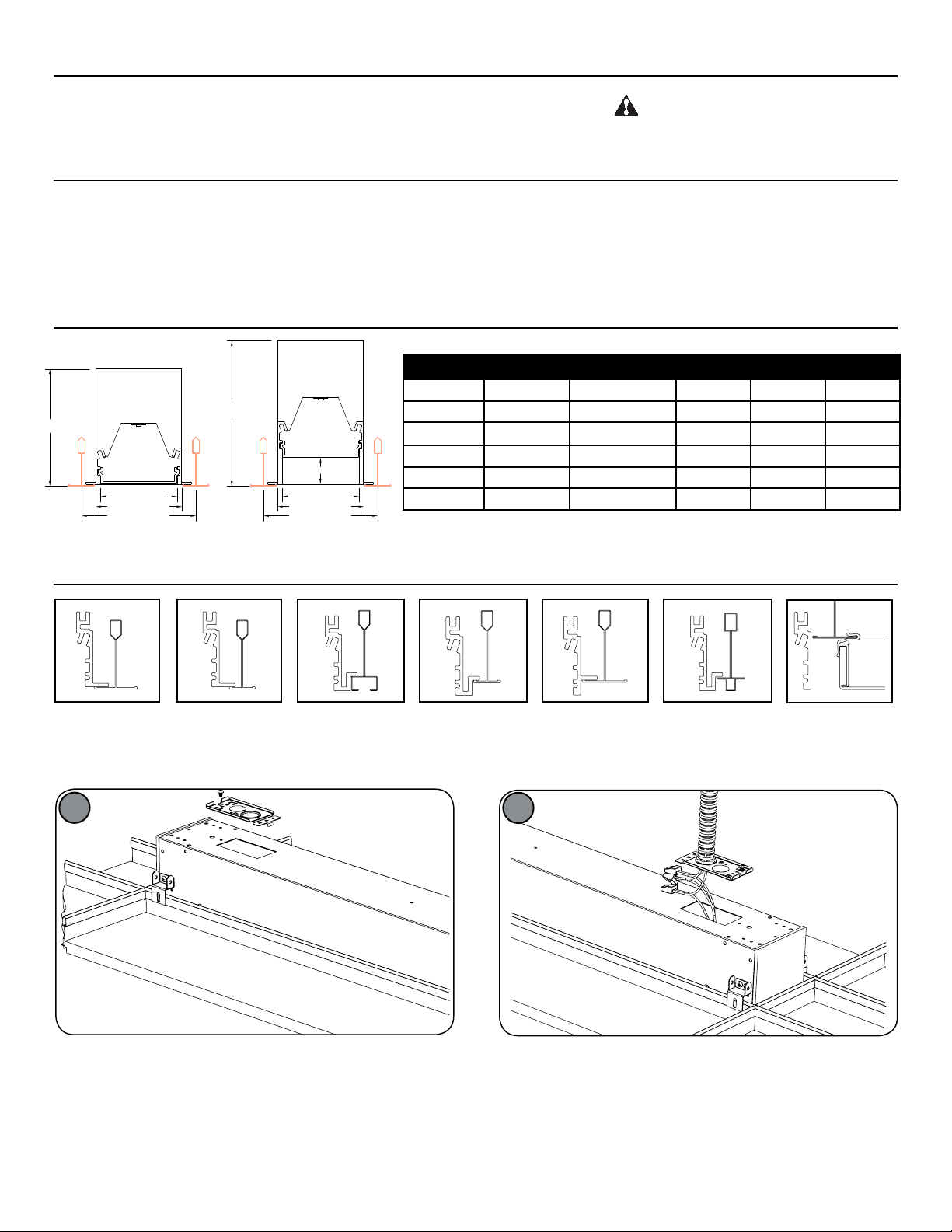
Cross Section and Grid Spacing Details
V
Y
X
Z
Flush S12xDR
W
1.000"
Regressed S12xRDR
Before starting any work, ensure that all
power sources are turned off. All work
must meet local/national electrical codes
and be preformed by a certified electrician.
• Push-in Quick Connects or wire nuts
• Alignment Pins
(pre-installed in fixture) (Continuous runs only)
• #8-32 2-1/2” Bolts and Nuts (Continuous runs only)
• 9/64” Allen Wrench (by others)
• 11/32” Flexible Nut Driver (by others)
• #2 Phillips Screwdriver (by others)
Define Cross Section Dimensions
All Grid V (Flush) W (Regressed) X Y Z
Define 1 1.734 2.705 1.500 1.180 2.500
Define 2 3.500 4.500 2.000 1.680 3.000
Define 3 4.000 5.000 3.000 2.680 4.000
Define 4 4.506 5.506 4.000 3.680 5.000
Y
X
Z
Define 5 5.000 6.000 5.000 4.680 6.000
Mounting Information - Extruded Trim Flange Details - Refer to submittal drawings for detailed flange information
ETG
15/16”
T-Grid
1
FTG
9/16”
T-Grid
STG
Slotted
T-Grid
FTT
9/16” Tegular
T-Grid
ETT
15/16” Tegular
T-Grid
2
ITG
9/16” Interlude
T-Grid
Trimless
Extruded Side
Prepare grid width spacing according to chart above and local
building code. Install fixture housing into grid. Ensure Grid brackets
secure over grid and fixture is resting on grid tee. Unscrew access
plate and slide to remove as shown.
2
COOPER LIGHTING SOLUTIONS IL519025EN Installation instructions
Connect shielded cable to access plate. Connect electrical wiring as
required using provided push-in connector. Ensure wires are fully
secure in connectors.
Page 3

3
Female Connector
Male Connector
Alignment Pin
8-32 Nut
8-32 Bolt
Alignment Pin
Tapered
End
4
Reattach access plate by sliding plate back into housing as shown
and secure access plate by re-installing screw.
5
FOR CONTINUOUS RUNS: Connect through wiring using the
provided push-in connectors, pressing together until they click into
place. Tuck wiring into fixture and push together ensuring alignment
pins are properly connected into mating features of the next fixture.
Secure run using #8-32 bolts and nuts on each side of fixture through
grid brackets.
Secure fixture at both ends using support wire according to local
building codes (not supplied).
6
FOR CONTINUOUS RUNS: Secure next fixture in row using support
wires on both sides of fixture. OPTIONAL STEP: Secure fixture to
grid using #8 screws through grid bracket. Required for seismic
installations. Repeat steps 5-6 as necessary.
7
Identify power feed side (end toward Beginning of Run). Prep wires
on power feed side for connection to previous section in the run / pattern. Install alignment pins into extrusion non-power feed side using
a hammer. Tapered side should face outward.
3
COOPER LIGHTING SOLUTIONS IL519025EN Installation instructions
8
Installation completed.FOR CORNER INSTALLATION: Prepare corner unit for installation.
Page 4

Cooper Lighting Solutions is a
registered trademark.
All trademarks are property
of their respective owners.
Cooper Lighting Solutions est une
marque de commerce déposée. Toutes
les autres marques de commerce sont
la propriété de leur propriétaire
respectif.
Cooper Lighting Solutions es una
marca comercial registrada. Todas las
marcas comerciales son propiedad de
sus respectivos propietarios.
Product availability, specifications,
and compliances are subject to
change without notice
La disponibilité du produit, les
spécifications et les conformités
peuvent être modifiées sans préavis
La disponibilidad de productos, las
especificaciones y los cumplimientos
están sujetos a cambio sin previo aviso
Lens Removal (Not typically required)
Insert Lens Removal Tool as shown, biased toward
one side of the lens. Lifting from center of lens may
cause lens to crack.
Tilt Lens Removal Tool as
shown and gently pry lens
up. Complete lens removal
by hand.
Warranties and Limitation of Liability
Please refer to www.cooperlighting.com for our terms and conditions.
Garanties et limitation de responsabilité
Veuillez consulter le site www.cooperlighting.com pour obtenir les conditions générales.
Garantías y Limitación de Responsabilidad
Visite www.cooperlighting.com para conocer nuestros términos y condiciones.
Cooper Lighting Solutions
121 Highway 74 South
1
Peachtree City, GA 30269
P: 770-486-4800
www.cooperlighting.com
© 2020 Cooper Lighting Solutions
All Rights Reserved
Printed in USA
Imprimé aux États-Unis
Impreso en los EE. UU.
Publication No. IL519025EN
August 21, 2019
 Loading...