

Page 1
Project Catalog # Type
4mm]
15-5/8" [398mm]
[86mm]
16-1/2" [411mm]
[86mm]
21-3/8" [543mm]
4mm]
20-7/8" [530mm]
4mm]
15-5/8" [398mm]
16-1/2" [411mm]
[85mm]
20-7/8" [530mm]
2-29/32"
4mm]
"
21-3/8" [543mm]
Prepared by Notes Date
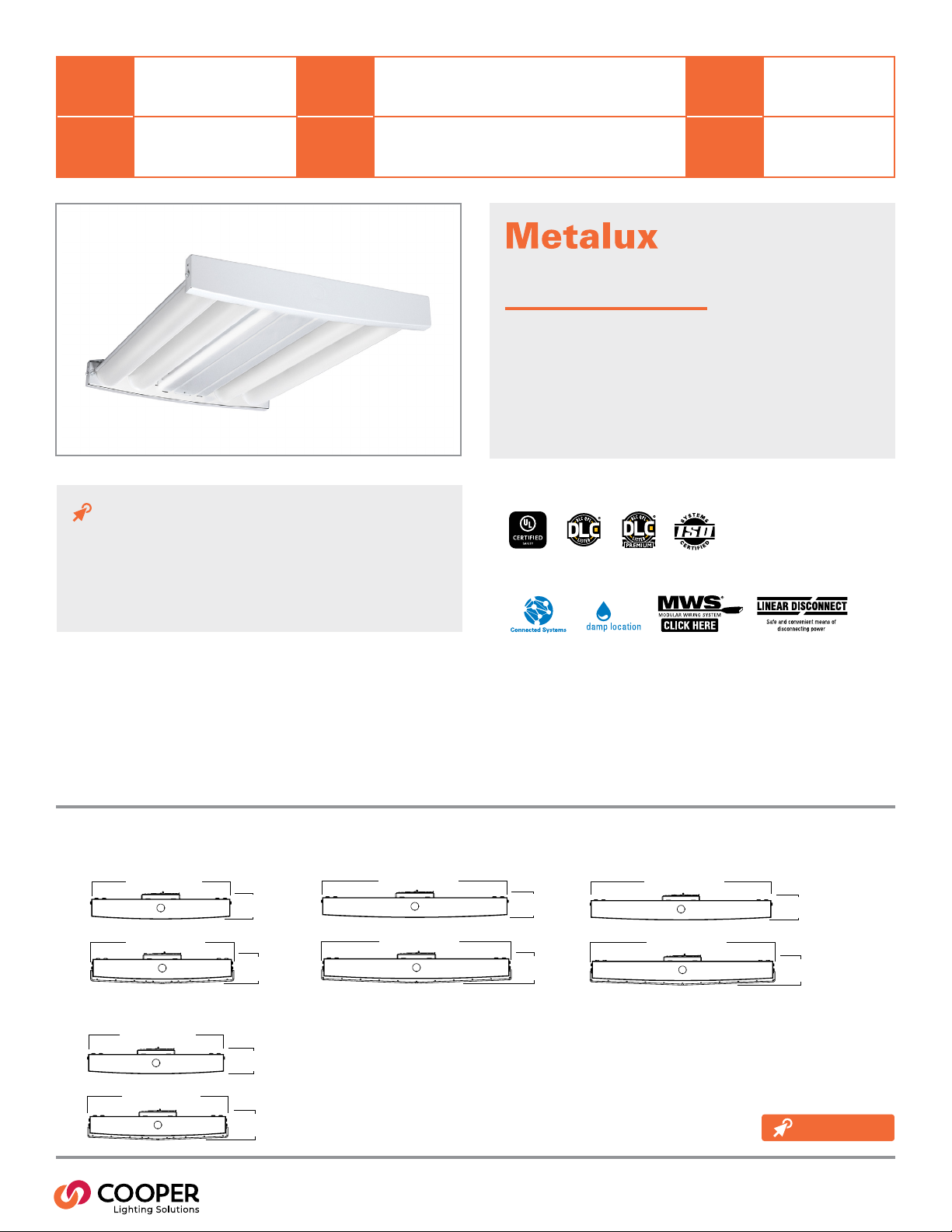
OHB LED High Ecacy
LED High Bay Eciency Luminaire
Typical Applications
Industrial • Commercial • Manufacturing • Food Processing •
Sports / Multi-Purpose
Interactive Menu
• Order Information page 2
• Photometric Data page 3
• Connected Systems page 5
• Product Warranty
Top Product Features
• Precision designed optical performance
• Offered in both standard and high ecacy versions
• High performance ecacy up to 210 lm/W
• Ecient 1-for-1 replacement of linear uorescent & HID xtures
• Lumen packages – 12K, 15K, 18K, 24K, 30K, 36K, 48K, 60K
• Narrow, medium, and wide distribution
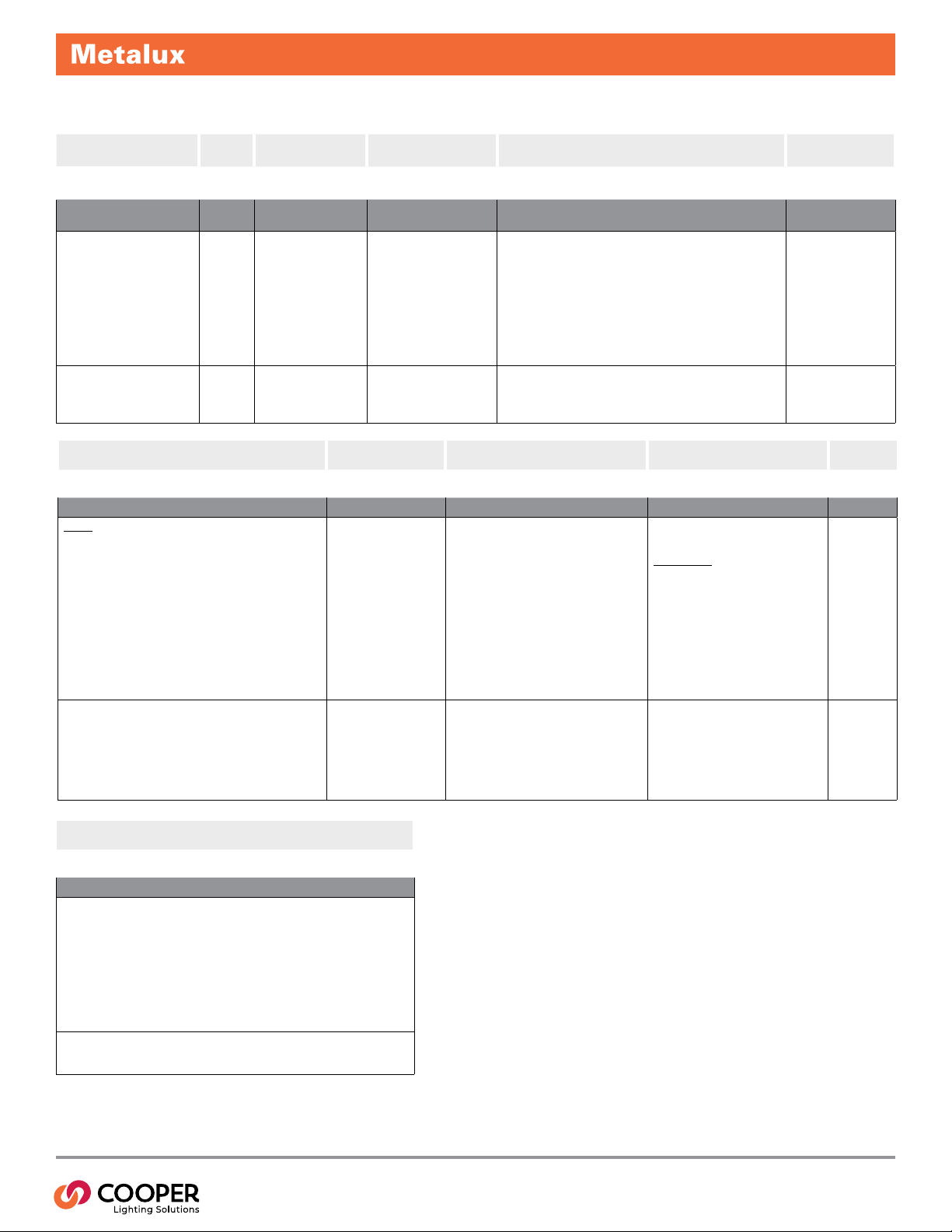
Dimensional and Mounting Details
OHB-12HE, 15HE, 18HE
2-7/8"
[7
OHB-24HE, 30HE
Product Certication
Product Features
OHB-48HE, 60HE
2-7/8"
[7
[7
OHB-36HE
3-3/8"
2-7/8"
[7
3-3/8"
3-3/8"
3-27/64
[87mm]
additional
product diagrams
PS507034EN page 1
February 24, 2021 8:18 AM
Page 2
Order Information
SAMPLE ORDER NUMBER: OHB-24HE-MFL-UNV-L840-CD-U Includes V Hangers for rapid installation
OHB HE
Series Revision Lumen Packages/
(17)
Series
Revision
OHB=Optimized High Bay [Blank] 12HE=12,000 Lumens
(17) DesignLights Consortium® Qualied
and classied for both DLC Standard and
DLC Premium, refer to www.designlights.
org for details.
Notes Notes Notes Notes
High Ecacy
Lumen Packages / High
Ecacy
15HE=15,000 Lumens
18HE=18,000 Lumens
24HE=24,000 Lumens
30HE=30,000 Lumens
36HE=36,000 Lumens
48HE=48,000 Lumens
60HE=60,000 Lumens
(7) 60HE conguration not
available with the combination
of Sensors or EBP plus 347V,
480V, or UNC.
Options Driver Type Wiring Options Packaging
Options Driver Type Wiring Options Packaging
EBP/TD
EL20W=20-watt 120V-277V emergency battery pack installed
EL20-W-REM=20-watt 120V-277V emergency battery pack remote
(4), (5), (8)
mounted
GTR2=Bodine Generator Transfer Device
ETRD=Iota Emergency Transfer Relay with dimming control
(4) With integral test switch/indicator/laser test. For approximate delivered lumens
multiply the lumens per watt of the desired xture by the wattage of the emergency
battery pack. (5) EM options available in 0°C - 45°C ambient. (6) Used to transfer
xture to secondary power during outage. Must be used in conjunction with UL
1008 device (provided by others). These options require 2 relays on xtures with
dimming drivers. ETRD option only requires one relay when used on a dimming
xture. A maximum of two devices can be used on one product. (8) GTR2 option is
only available with 4ft xtures (36K, 48K, and 60K lumens). (10) High Ambient not
available with integrated emergency.
(8)
Notes Notes Notes
(4), (5), (10)
(6)
Distribution/Shielding Voltage CCT/CRI
Distribution/Shielding Voltage
N=Narrow
MFL=Medium Frosted
MCL=Medium Clear
W=Wide
NL=No Lens
(7)
(14) NL (Non Lensed) versions not
available with 36HE, 48HE, and 60HE
lumen packages.
CD=0-10V Dimming Driver
5LTD=Fifth Light DALI
(15) Sensor or UNC not available
in conjunction with 5LTD driver.
(16) Ambient temperatures limited
to 40C when using emergency,
sensors, or 5LTD in conjunction
with 347V or 480V.
(14)
(15), (16)
120V=120 Volt
277V=277 Volt
347V=347 Volt
480V=480 Volt
UNV=Universal Voltage 120-277
UNC=Universal Voltage 347/480
(1) Voltage must be specied when ordered with plugs or emergency drivers. (2) When
ordering sensors option, specify as UNV (for 120V or 277V), 347V or 480V. (16) Ambient
temperatures limited to 40C when using emergency, sensors, or 5LTD in conjunction with
347V or 480V.
C3 (1)=1 Circuit, 3’ Cord with no Plug
C3 (2)=2 Circuits, 3’ Cord with no Plug
C6 (1)=1 Circuit, 6’ Cord with no Plug
C6 (2)=2 Circuits, 6’ Cord with no Plug
PC3/120=(NEMA L5-15P) 3’ Cord with NEMA Plug
PC3/277=(NEMA L7-15P) 3’ Cord with NEMA Plug
PC3/347=(NEMA L24-20P) 3’ Cord with NEMA Plug
PC3/480=(NEMA L8-20P) 3’ Cord with NEMA Plug
PC6/120=(NEMA L5-15P) 6’ Cord with NEMA Plug)
PC6/277=(NEMA L7-15P) 6’ Cord with NEMA Plug)
PC6/347=(NEMA L24-20P) 6’ Cord with NEMA Plug
PC6/480=(NEMA L8-20P) 6’ Cord with NEMA Plug
(1), (2), (16)
MP=Modular Plug
PAF =Painted After Fabrincation
HA=High Ambient
Motion Sensors
MS=360° or 180° Motion Sensor Installed,
(specify voltage)
SVPD3=Integrated Occupancy and Daylight
Dimming Sensor, 1200 sq. ft. coverage
OEFP010VMV=Occupancy Sensor with
Integrated Photocell
FSP-211/L7-U=PIR Occupancy Sensor with
Integral 0-10V Dimming
LWR=Enlighted Sensor system
ZW-SWPD3=Integrated Wavelinx Wireless
Sensor, 1200 sq ft. coverage
ZW=WaveLinx Wireless Ready (does not
include sensor)
(2) When ordering sensor or EBP/TD option, specify
as UNV (for 120V or 277V), 347V or 480V. (3) Requires
use of MC or MPC cord accessories, specify voltage
for plugs (MP). (10) High Ambient not available with
integrated emergency. (13) Refer to Ambient Chart for
temperature ratings.
(3)
(10), (13)
(2)
(2)
(2)
(2)
(2)
(2)
CCT/CRI
L730=70CRI / 3000K
L735=70CRI / 3500K
L740=70CRI / 4000K
L750=70CRI / 5000K
L830=80CRI / 3000K
L835=80CRI / 3500K
L840=80CRI / 4000K
L850=80CRI / 5000K
L930=90CRI / 3000K
L935=90CRI / 3500K
L940=90CRI / 4000K
L950=90CRI / 5000K
U=Unit Pack
PAL C=Job
Pack, in carton
(2)
Accessories
Accessories (order separately)
OHB-WG162=Wire guard for 12HE, 15HE, and 18HE
OHB-WG222=Wire guard for 24HE and 30HE
OHB-WG164=Wire guard for 36HE
OHB-WG224=Wire guard for 48HE and 60HE
FH-1=Fixture Hook
FL-1=Fixture Loop
OHB-SPM=Single Point Mounting Hub
MPC3=3’ Modular Power Cord & Plug (Specify Voltage)
MPC6=6’ Modular Power Cord & Plug (Specify Voltage)
MC3=3’ Modular Power Cord
MC6=6’ Modular Power Cord
SWPD3=WaveLinx Wireless Sensor (to be installed with “ZW” sensor ready xtures only)
(9) OHB-SPM mounting not available with EL20W or ETRD options. (12) Must be used in conjunction with OHBSPM accessory for proper installation.
(12)
(12)
(9)
Notes
PS507034EN page 2
February 24, 2021 8:18 AM
Page 3

0˚ 30˚
˚
˚
˚
˚
20˚
˚
˚
10˚
0˚ 30˚
˚
˚
˚
˚
20˚
˚
˚
10˚
0˚ 30˚
˚
˚
˚
˚
20˚
˚
˚
10˚
0˚ 30˚
˚
˚
˚
˚
20˚
˚
˚
10˚
Product Specications
Construction
• Rugged and durable scalable design with
rigid, steel center channel
• Mechanically attached end caps provide
strength and durability
• Suspension mounting with optional wire
hook and chain set or cable; Single
monopoint mounting with SPM tong hanger
Electrical
• Long-Life LED system coupled with electrical
driver for optimal performance
• LED’s available in 3000K, 3500K, 4000K and
5000K with 70 CRI, 80 CRI and 90 CRI options
• Electronic drivers are available for 120-277V,
347V and 480V applications
• 0-10V dimming control (standard)
• Operating temperature of -40°C to 55°C (refer
to chart)
Emergency Battery Pack Option
• 20-watt, 120-277V integral emergency battery
pack available to meet critical life-safety lighting
requirements
• 90-minute batteries provide constant power to
the LED system, ensuring code- compliance
• Emergency/generator transfer options available
(see ordering information for details)
Optics
• Precision designed optics deliver even
illumination
• Offered in Narrow, medium and wide
distributions
Shielding
• Standard lensing provides additional LED
protection and optical control
• Optional wire guards available for more complex
environments
Controls
• Integral occupancy sensor (SVPD3) option provides
600 sq. ft. to up to 1250 sq. ft. of coverage for
occupancy sensing and daylight harvesting
• Integral 360° or 180° motion sensor
• Integrated Wavelinx Wireless Sensor option
provides 1200 sq. ft. coverage
• WaveLinx wireless enabled (does not include
sensor)
Finish
• White enamel nish preceded by a multistage
cleaning cycle
• Iron phosphate coating with rust inhibitor
protects against contaminnts and oxidation
OHB HE
Compliance
• cULus listed for damp locations
• LED modules comply with IESNA LM-79 and
LM-80 standards
• DesignLights Consortium® Qualied and
classied for both DLC Standard and
DLC Premium (refer to www.designlights.org for
details)
Warranty
• Five year warranty standard.
Photometric Data
90
2133
4266
6399
8532
4471
8941
13412
17883
80
70
60
50
40
90
80
70
60
50
40
OHB-24HE-MCL-UNV-L850-CD-U
Electronic Driver
Linear LED 5000K
Spacing criterion: (II) 1.3 x mounting height,
(⊥) 1.27 x mounting height
Lumens: 24645
Input Watts: 132W
Ecacy: 186.7 LPW
Test Report: OHB-24HE-MCL-UNV-L850-CD-U.IES
OHB-24HE-N-UNV-L850-CD-U
Electronic Driver
Linear LED 5000K
Spacing criterion: (II) 1.51 x mounting height,
(⊥) 0.53 x mounting height
Lumens: 24029
Input Watts: 132W
Ecacy: 182 LPW
Test Repor t: OHB-24HE-N-UNV- L850- CD-U.IES
2101
4202
6303
8404
2556
5113
7669
10226
OHB-24HE-MFL-UNV-L850-CD-U
90
Electronic Driver
80
Linear LED 5000K
70
Spacing criterion: (II) 1.2 x mounting height,
(⊥) 1.28 x mounting height
60
Lumens: 23894
50
Input Watts: 132W
Ecacy: 181 LPW
40
Test Report: OHB-24HE-MFL-UNV-L850-CD-U.IES
OHB-24HE-W-UNV-L850-CD-U
90
Electronic Driver
80
Linear LED 5000K
70
Spacing criterion: (II) 1.16 x mounting height,
(⊥) 2.19 x mounting height
60
Lumens: 24377
50
Input Watts: 132W
Ecacy: 184.7 LPW
40
Test Report: OHB-24HE-W-UNV-L850- CD-U.IES
View IES les
PS507034EN page 3
February 24, 2021 8:18 AM
Page 4

Energy and Performance Data
OHB - High Ecacy 5000K 70CRI
Lumen Output Watts Ecacy (LPW)
Catalog Number
OHB-12HE 13045 12971 13379 13234 13907 68 193 192 198 196 206
OHB-15HE 16113 16022 16526 16346 17178 83 193 192 198 196 206
OHB-18HE 19594 19484 20097 19879 20890 102 192 191 197 195 204
OHB-24HE 25526 25383 26181 25896 27214 132 194 193 199 197 207
OHB-30HE 32410 32228 33241 32880 34552 172 189 188 194 191 201
OHB-36HE 38345 38129 39328 38901 – 201 190 189 195 193 –
OHB-48HE 51874 51583 53205 52626 – 261 199 197 204 201 –
OHB-60HE 62913 62560 64527 63825 – 333 189 188 194 192 –
Catalog Number
OHB-12HE 12279 12210 12594 12457 13091 68 182 181 187 185 194
OHB-15HE 15167 15082 15557 15387 16170 83 182 181 187 185 194
OHB-18HE 18445 18341 18918 18712 19664 102 180 179 185 183 192
OHB-24HE 24029 23894 24645 24377 25617 132 183 182 187 185 195
OHB-30HE 30509 30337 31291 30951 32525 172 178 177 182 180 189
OHB-36HE 36095 35893 37021 36619 – 201 179 178 184 182 –
OHB-48HE 48831 48557 50084 49539 – 261 187 186 192 190 –
OHB-60HE 59222 58890 60742 60081 – 333 178 177 182 180 –
N MFL MCL W NL 277V N MFL MCL W NL
OHB - High Ecacy 5000K 80CRI
Lumen Output Watts Ecacy (LPW)
N MFL MCL W NL 277V N MFL MCL W NL
OHB HE
Ambient Ratings
Lumen Package Ambient Rated
OHB-12HE 55°C – 45ºC
OHB-15HE 55°C – 45ºC
OHB-18HE 45°C 55°C 45ºC
OHB-24HE 55°C – 45ºC
OHB-30HE 55°C – 45ºC
OHB-36HE 45°C 55°C 45ºC
OHB-48HE 55°C – 45ºC
OHB-60HE 55°C – 45ºC
(HA) High
Ambinet EM
Energy Data
Input Watts:
12HE (12,000 lumens)=68W
15HE (15,000 lumens)=83W
18HE (18,000 lumens)=120W
24HE (24,000 lumens)=132W
30HE (30,000 lumens)=172W
36HE (36,000 lumens)=2101W
48HE (48,000 lumens)=263W
60HE (60,000 lumens)=334W
Modular Power Supply Option
Modular Power Supply option is available for use with all F-Bay products. The modular power supply allows external xture access for safe and easy servicing. There is no need to remove lamps or reectors
to disconnect xture power with Modular Power Supply. Access to the individual xture’s power supply
allows servicing without turning off all the xtures, disrupting occupants. F-Bay Modular Power Supply is
a time saver in installation – simply plug & power.
Code Compliance
• UL/cUL Certied for Make/Break
under load (UL2549)
• Meets NEC requirements for
ballast disconnect (NEC 410.73G)
• Receptacle complete with
insulating/dust cap
Shipping Data
Catalog No. Wt.
OHB-12HE 10 lbs.
OHB-15HE 13 lbs.
OHB-18HE 13 lbs.
OHB-24HE 13 lbs.
OHB-30HE 16 lbs.
OHB-36HE 20 lbs.
OHB-48HE 20 lbs.
OHB-60HE 20 lbs.
Lumen Maintenance
Ambient
Temperature
25ºC > 96% > 240,000
TM-21 Lumen
Maintenance
(60,000 hours)
Theoretical
L70
(Hours)
1. Modular Power Supply Receptacle supplied
mounted into xture Access Plate.
2. Modular Power Cord & Plugs in 120, 277, 347,
& 480V congurations for easy plug & power
into existing supply.
No internal xture
access required
for installation or
disconnecting power.
PS507034EN page 4
February 24, 2021 8:18 AM
Page 5

Control Systems
• WaveLinx Wireless
• WaveLinx Wired
• WaveLinx Lite
OHB HE
Systems comparison chart
Cooper Lighting Solutions provides many lighting system solutions
designed to satisfy code requirements and meet the unique needs of
any project.
Standalone Controlled Connected Enterprise
WaveLinx Lite WaveLinx Wireless Trellix
Occupancy Yes Yes Yes Yes
Daylighting Yes Yes Yes Yes
Gateways – – 1 WAC 300 WACs
Devices – 50 per Area (1400 per site) 150 per WAC 45,000 per Core Enterprise
Software – WaveLinx Lite Mobile App WaveLinx Mobile App Trellix Core
Areas – 28 per Site 16 per WAC up to 4,800
Zones – 16 per Area 16 per Area up to 76,800
Scheduling – – Local Global
VividTune™ – – Yes Yes
Plug-Load Control – – Yes Yes
Integration – – – BACnet, API
Dashboards – – – Energy, Occupancy
Configuration – Installer Technician Technician / IT
SCALABILITY
devices areas floors buildings
PS507034EN page 5
February 24, 2021 8:18 AM
Page 6

Dimensional and Mounting Details
4mm]
15-5/8" [398mm]
[86mm]
16-1/2" [411mm]
23-1/2" [595mm]
23-1/2" [595mm]
[86mm]
21-3/8" [543mm]
4mm]
20-7/8" [530mm]
23-1/2" [599mm]
23-1/2" [599mm]
4mm]
15-5/8" [398mm]
16-1/2" [411mm]
[85mm]
45-3/8" [1152mm]
45-3/8" [1152mm]
20-7/8" [530mm]
2-29/32"
"
[87mm]
21-3/8" [543mm]
45-3/8" [1152mm]
45-3/8" [1152mm]
OHB-12HE, 15HE, 18HE
OHB HE
OHB-36HE
2-7/8"
[7
3-3/8"
2-7/8"
[7
3-3/8"
OHB-24HE, 30HE
2-7/8"
[7
3-3/8"
OHB-48HE, 60HE
[74mm]
3-27/64
Cooper Lighting Solutions
1121 Highway 74 South
Peachtree City, GA 30269
P: 770-486-4800
www.cooperlighting.com
© 2021 Cooper Lighting Solutions
All Rights Reserved.
Specifications and dimensions
subject to change without notice.
PS507034EN page 6
February 24, 2021 8:18 AM
 Loading...