

Page 1
Project Catalog # Type
Prepared by Notes Date
Portfolio
LD8B ER8B 8LB
8" Narrow, Medium, or Wide
New Construction Downlight
1,000-20,000 Lumen
Typical Applications
Oce • Education • Healthcare • Hospitality
Interactive Menu
Product Certication
• Order Information page 2
• Product Specications page 4
• Energy Data page 5
• Photometric Data page 6
Product Features
• Connected Systems page 8
• Product Warranty
Top Product Features
• 1,000 to 20,000 lumens; Offered in 80, 90 and 97 CRI; narrow beam, medium beam and wide beam distributions
• Two-stage reector system produces smooth beam; Color variation within 3-step MacAdam ellipses
• Flexible disconnect for easy LED engine replacement and installation
• 2400K, 2700K, 3000K, 3500K, 4000K, 5000K; D2W™ option from 3000K to 1850K
• W2N tunable white CCT range 2700K to 6500K or 2000K to 5000K
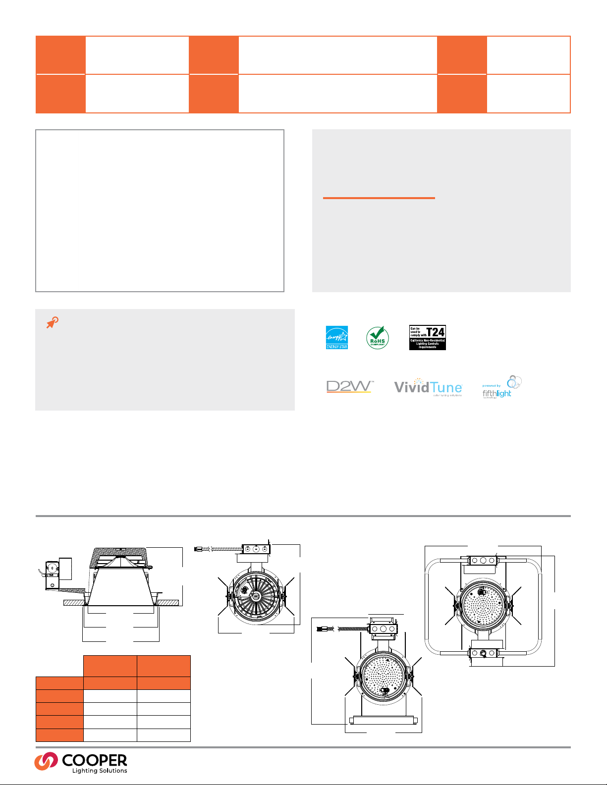
Dimensional and Mounting Details
21-1/2"
[544mm]
14-3/4"
[375mm]
with Battery
8-3/8"
[211mm]
Ø 9-3/8"
[238mm]
Ø 9-3/4"
[248mm]
MAX. HEIGHT
SEE TABLE
13-31/32"
[355mm]
20-1/4"
[514mm]
Low Lumen
(1000-7000)
Distribution Max. Height Max Height
Narrow
Medium
Wide
Shallow
7-25/32" 9-3/4"
7-5/16" 9-9/32"
6-11/16" 8-11/16"
4-26/32" 6-26/32"
High Lumen
(8000-20000)
19-7/8"
[505mm]
13-31/32"
[355mm]
PS502114EN page 1
April 16, 2021 10:12 AM
Page 2
Portfolio
Order Information
SAMPLE ORDER NUMBER: LD8B50D010IEMBOD
Housing Lumens Voltage Driver Options
Housing Lumens
LD8B=LED Downlight
8" Nominal Aperture
LD8BCP=LED
Downlight 8" Nominal
Aperture, Chicago
Plenum
10=1000 lumens
15=1500 lumens
20=2000 lumens
30=3000 lumens
40=4000 lumens
50=5000 lumens
60=6000 lumens
70=7000 lumens
80=8000 lumens
90=9000 lumens
100=10000 lumens
120=12000 lumens
150=15000 lumens
175=17500 lumens
200=20000 lumens
(1) Nominal Lumens will vary depending on
selected color, driver and reflector nish.
(8) Product is marked spacing and must be
installed with the following minimum spacing
-Center to center of adjacent luminaires: 36"
-Center of luminaire to side of building member: 18"
-Minimum overhead: 1/2"
-20,000 Lumens minimum overhead: 6"
(8)
(8)
(8)
(8)
Notes
(1)
Blank=120-277 7000 lumen and below.
3=347V step down transformer
(8)
(8)
(8)
(8)
(8)
(10) For single driver.
(11) 347V step down transformer only available up to
7000 Lumen
Voltage
Notes
(10)
(11)
1000-4000 Lumen
D010=0-10V 120-277V Dimming, 1 to 100%
D010TR=0-10V 120-277V or 120V Line Voltage
Dimming, 1% to 100%
DE010=0-10V Linear Dimming, 0% to 100%, 120V-277V
D5LT=Fifth Light® DALI DT6 Logarithmic Dimming,
0% to 100%, 120V-277V
DMX=DMX/RDM Logarithmic Dimming, 0% to 100%,
120V-277V
DMXC5=DMX/RDM Logarithmic Dimming, 0% to 100%,
120V-277V, with RJ45 connection
DL2=Lutron® Hi-Lume Forward Phase Dimming, 1%
to 100%, 120V Only
DLE=Lutron Ecosystem dimming 1% to 100%
DMXC5=DMX/RDM Logarithmic Dimming 0% to
100% with RJ45 connection
1000-3000 Lumen
DLV =Low voltage dimming driver (1-100%) for use with
DLVP system
5000, 6000, and 7000 Lumen
D010TE=0-10V or Trailing Edge Dimming,
5% to 100%, 120V-277V (120V Only for Trailing Edge
Dimming)
Tunable white 1000-2000
DE010W2N=0-10V dimming, 0% to 100%,120V
D5LTW2N=Fifth Light DALI DT6 Logarithmic Dimming,
0% to 100%
(12) DMX xtures default to full on upon loss of DMX signal.
(13) For D2W up to 3000 lumens.
(14) Not for use with D2W.
1 Driver 2 and 3 Drivers
(13)
(12)
(14)
LD8B ER8B 8LB
Driver Options
4000 and 6000 Lumen D2W (2 Drivers)
6000, 8000 and 9000 Lumen (2 Drivers)
9000 Lumen D2W (3 Drivers)
12,000 Lumen (3 Drivers)
1D010=0-10V, 120V Dimming, 1% to 100%
2D010=0-10V, 277V Dimming, 1% to 100%
1D010TR=0-10V or 120V Line Voltage Dimming, 1%
to 100%
2D010TR=0-10V, 277V Dimming, 1% to 100%
1DE010=0-10V, 120V Linear Dimming, 0% to 100%
2DE010=0-10V, 277V Linear Dimming, 0% to 100%
1D5LT=120V Fifth Light® DALI DT6 Logarithmic
Dimming, 0% to 100%
2D5LT=277V DALI DT6 Logarithmic Dimming,
0% to 100%
1DMX=120V, DMX/RDM Logarithmic Dimming,
(12)
0% to 100%
2DMX=277V, DMX/RDM Logarithmic Dimming,
(12)
0% to 100%
1DMXC5=120V, DMX/RDM Logarithmic Dimming
0% to 100% with RJ45 connection
2DMXC5=277V, DMX/RDM Logarithmic Dimming
0% to 100% with RJ45 connection
1DL2=120V Lutron® Hi-Lume Forward Phase
Dimming, 1% to 100%
1DLE=120V, Lutron Ecosystem dimming 1% to 100%
2DLE=277V, Lutron Ecosystem dimming 1% to 100%
10,000, 12,000, 15,000, 17,500, 20,000 Lumen
1D010TE=0-10V or Trailing Edge Dimming,
5% to 100%, 120V
2D010TE=0-10V, 5% to 100%
Tunable white 3000-4000
1DE010W2N=0-10V dimming, 0% to 100%,120V
2DE010W2N=0-10V dimming, 0% to 100%,277V
1D5LTW2N=120V, Fifth Light DALI DT6 Logarithmic
Dimming, 0% to 100%
2D5LTW2N=277V, Fifth Light DALI DT6 Logarithmic
Dimming, 0% to 100%
Notes
Color Control Options
Color Control
Blank=No color control or D2W for 2000
lumens and below
D2W=For 4000, 6000 and 9000 dim
2 warm
2050=For W2N 2000K - 5000K
2765= For W2N 2700K - 6500K
(9)
WTA=Factory installed WaveLinx Sensor Kit
(2) (3) (16)
WTK=Factory installed WaveLinx Lite Sensor Kit
(2) (3) (17)
EMBOD=Bodine® Emergency Module with Remote Test Switch
EMBOD7ST =Bodine® Emergency Module with Self Test Remote
Test Switch
EM7=7W Emergency Module with Remote Test Switch
EM14=14W Emergency Module with Remote Test Switch
IEMBOD=Bodine® Emergency Module with Integral Test Switch
IEM7=7W Emergency Module with Integral Test Switch
IEM14=14W Emergency Module with Integral Test Switch
Notes
(9) Field required for D2W 4000, 6000 and 9000
lumens only.
(2) Refer to system specications for additional information, features and benets. Order either factory installed option or accessory, use with 0-10V driver.
(3) Not available with Chicago Plenum or IC rating.
(4) ULus listed only.
(16) WTA = WaveLinx wireless sensor kit for daylight dimming, PIR motion sensing, and optional RLTS - Real Time Location Services, use with 0-10V only.
(17) WTK = WaveLinx Lite tile mount sensor kit for daylight dimming, PIR motion sensing, use with D010 only (Refer to WaveLinx Lite system specications)
(3)
Options
(3)
EMV7=7W Low Voltage Emergency Module with Remote
(4)
(3)
(3)
(3)
(3)
(3)
Test Switch
EMV14=14W Low Voltage Emergency Module with
Remote Test Switch
IEMV7=7W Low Voltage Emergency Module with
(3)
Integral Test Switch
IEMV14=14W Low Voltage Emergency Module with
Integral Test Switch
(4)
(4)
(4)
Notes
PS502114EN page 2
April 16, 2021 10:12 AM
Page 3

Portfolio
Order Information
SAMPLE ORDER NUMBER: ER8B30408035
Power Module Lumen Levels Color
Notes
(1)
80 CRI
8027= 80CRI, 2700K
8030= 80CRI, 3000K
8035= 80CRI, 3500K
8040= 80CRI, 4000K
8050= 80CRI, 5000K
Dim 2 Warm 1 Driver
109030D2W=1000 Lumen, 90 CRI, Dim 2 Warm, IC Rated
159030D2W=1500 Lumen, 90 CRI, Dim 2 Warm, IC Rated
209030D2W=2000 Lumen, 90 CRI, Dim 2 Warm, IC Rated
309030D2W=3000 Lumen, 90 CRI, Dim 2 Warm
Dim 2 Warm 2 Drivers
409030D2W=4000 Lumen, 90 CRI, Dim 2 Warm
609030D2W=6000 Lumen, 90 CRI, Dim 2 Warm
Dim 2 Warm 3 Drivers
909030D2W=9000 Lumen, 90 CRI, Dim 2 Warm
(16) Non-IC.
90 CRI
9027= 90CRI, 2700K
9030= 90CRI, 3000K
9035= 90CRI, 3500K
9040= 90CRI, 4000K
9050= 90CRI, 5000K
Power Module Lumen Levels
ER8B=8" LED Module 1 Driver
1020=1000, 1500, or 2000 Lumens
3040=3000 or 4000 Lumens
5070=5000, 6000, or 7000 lumens
2 Drivers
60=6000 lumens, 2 LEDs
80120=8000, 9000, 10000, or 12000 lumens
3 Drivers
120=12000 lumens, 3 LEDs
150200=15000, 17500 or 20000 lumens
(1) Nominal Lumens will vary depending on selected color,
driver and reflector nish.
LD8B ER8B 8LB
Color
97 CRI
9727= 97CRI, 2700K
9730= 97CRI, 3000K
W2N Tunable White 1 Driver
10W2N902050=1000 lumens, 90 CRI, Tunable white 2000K - 5000K
10W2N902765=1000 lumens, 90 CRI, Tunable white 2700K - 6500K
15W2N902050=1500 lumens, 90 CRI, Tunable white 2000K - 5000K
15W2N902765=1500 lumens, 90 CRI, Tunable white 2700K - 6500K
20W2N902050=2000 lumens, 90 CRI, Tunable white 2000K - 5000K
20W2N902765=2000 lumens, 90 CRI, Tunable white 2700K - 6500K
W2N Tunable White 2 Drivers
30W2N902050=3000 lumens, 90 CRI, Tunable white 2000K - 5000K
30W2N902765=3000 lumens, 90 CRI, Tunable white 2700K - 6500K
40W2N902050=4000 lumens, 90 CRI, Tunable white 2000K - 5000K
40W2N902765=4000 lumens, 90 CRI, Tunable white 2700K - 6500K
Notes
(16)
SAMPLE ORDER NUMBER: 8LBM1LI
Trim Distribution Flange Finish Options
Notes
(16)
(5)
0=White Polymer Trim Ring
1=Self-flanged
2=White Painted Self-flanged
Flange Finish Options
(7)
LI=Specular Clear
H=Semi-Specular Clear
WMH=Warm Haze
WH=Wheat
GPH=Graphite Haze
B=Specular Black
MW=Matte White
E=Integral Emergency Test Switch Hole
Notes
(7) Flange is the same nish as the reflector.
(6) Only available with Narrow, Medium and Wide Spun Aluminum trims. Required for use
with all IEMBOD, IEM7, IEM14, IEMV7 and IEMV14 housings.
Accessories
Accessories
(15)
(17)
Notes
Trim Distribution
8LB=8”
Reflector
HSA8=Slope Adapter for 8" Aperture Housings, Specify Slope
Bar Hangers
HB26=C-channel Bar Hanger, 26” Long, Pair
HB50=C-channel Bar Hanger, 50” Long, Pair
Transformers
H347=347 to 120V Step Down Transformer, 75VA
H347200=347 to 120V Step Down Transformer, 200VA
Connected Lighting Systems
WTA = Field installed WaveLinx sensor Kit
WTK = Field installed WaveLinx Lite Sensor Kit
(2) Refer to system specications for additional information, features and benets. Order either factory installed option or accessory, use with 0-10V driver.
(15) Consult accessory specication sheet for ordering information.
(16) WTA = WaveLinx wireless sensor kit for daylight dimming, PIR motion sensing, and optional RLTS - Real Time Location Services, use with 0-10V only.
(17) WTK = WaveLinx Lite tile mount sensor kit for daylight dimming, PIR motion sensing, use with D010 only (Refer to WaveLinx Lite system specications)
N=Narrow Spun Aluminum
M=Medium Spun Aluminum
W=Wide Spun Aluminum
S=Shallow Spun Aluminum
(5) Beam angles are nominal with LI nish trims. See chart.
(2)
(6)
Notes
PS502114EN page 3
April 16, 2021 10:12 AM
Page 4

Portfolio
Product Specications
Lower Shielding Reflector
• Self-anged, spun .060" thick aluminum lower
reector
• Lensed upper optical chamber
• Provides superior lumen output with minimal
source brightness
• Available in all Portfolio Alzak
Trim Retention
• Two torsion springs hold lower reector ange
tightly to the nished ceiling surface
Plaster Frame/Collar
• Die-cast aluminum 1-1/2" deep collar
accommodates ceiling materials up to 2"
Universal Mounting Bracket
• Accepts 1/2" Electric Metallic Tube (EMT),
C-channel and bar hangers
• Adjusts 5" vertically from above and below the
ceiling
Junction Box
• Four 1/2" and two 3/4" trade size pry outs
positioned to allow straight conduit runs
• Listed for eight #12 AWG (four in, four out) 90°C
conductors and feed-through branch wiring
Thermal
• Aluminum heat sink conducts heat away from the
LED module for improved performance and longer
life
LED System
• Contains a plurality of high brightness white LED’s
combined with a high reectance upper reector
and transitional lens producing even distribution
with no pixilation
• Lumen output shall not decrease by more than
10% over the minimum life of 55,000 hours
(L90 > 55,000 hours)
• Color variation within 2-step MacAdam ellipses
• Flexible disconnect allows for tool-less replacement
of LED engine from below ceiling
• Available in 2700K, 3000K, 3500K, 4000K and
5000K correlated color temperature (CCT)
• Available in 80, 90 or 97 color rendering index (CRI)
®
nishes
VividTune™ Color Tuning Solutions
• D2W™ – Dim-to-Warm shifts CCT from 3000K to
1850K as xture dims, mimicking halogen sources
• W2N – Tunable white CCT range from 2700K to
6500K or 2000K to 5000K; 90 CRI
Driver
• Combination 0-10V/trailing edge driver provides
icker free dimming from 100% to 10%
• Optional 1% 0-10V, Fifth Light, DMX or Lutron
Ecosystem
• Driver can be serviced from above or through the
aperture
• 1,000-7,000 lumens utilize one driver; 8,000-12,000
lumens utilize two drivers; 15,000-20,000 lumens
utilize three drivers; reference ordering information
for other variations
• Distributed low voltage power system combines
power, lighting, and controls with ease of
installation.
®
Connected Lighting System Options
Two WaveLinx connected systems to choose
from. Refer to WaveLinx system specications and
application guides for details.
WaveLinx Wireless System Tilemount Sensor Kit
• WaveLinx Wireless WTA tile mount sensor kit offers
daylight dimming, PIR motion sensing, scene and
zone conguration, automatic commissioning;
and optional RLTS - Real Time Location Services
available.
WaveLinx Lite System Tilemount Sensor Kit
• WaveLinx Lite WTK tile mount sensor kit offers
daylight dimming and PIR motion sensing, scene
and grouping conguration.
WaveLinx Tilemount Kits Application
• The WTA and WTK tilemount kits include a control
module mounted on the luminaire junction box via
1/2” knock-out, and a tilemount sensor on 54-inch
whip; for ceiling installation by direct-mount spring
clips or via mounting bracket in octagon ceiling
boxes.
• The WTA and WTK tilemount kits may be ordered
as factory installed on the luminaire, or ordered
separately as a eld installed accessory kit.
LD8B ER8B 8LB
Compliance
• Thermally protected
• cULus Listed for protected wet locations
• cULus Certied IP65 below ceiling
• Optional City of Chicago environmental air (CCEA)
marking for plenum applications
• EMI/RFI emissions per FCC 47CFR Part 18 Class B
consumer limits
• Insulated ceiling (IC) rated up to 2,000 lumens;
3,000 lumens and above are non-IC rated (insulation
must be kept 3" from top and sides of housing)
• RoHS compliant
• T24 compliant
• IP20 above ceiling
• IP65 below ceiling nish
• Photometric testing completed in accordance with
IES LM-79 standards
• Lumen maintenance projections in accordance with
IES LM-80-08 and TM-21-11
• 6,000 lumens and above are marked spacing and
must follow spacing requirements
Warranty
• Five-year warranty
PS502114EN page 4
April 16, 2021 10:12 AM
Page 5

Portfolio
Color Metric Summary
LD8B ER8B 8LB
8027
R_f 93.2
R_g 94.1
CRI 81.3
R_9 0.7
9030
R_f 91.6
R_g 98.6
CRI 93.2
R_9 60.2
8030
R_f 83.4
R_g 94.4
CRI 82.4
R_9 4.5
9035
R_f 90.9
R_g 98.3
CRI 93.3
R_9 63.1
Energy
ENERGY DATA
Sound Rating: Class A standards
(Values at non-dimming line voltage)
Minimum Starting Temperature: -20°C (-4°F)
EMI/RFI: FCC Title 47 CFR, Part 15, Class B (Consumer)
Power Factor: >0.90
Input Frequency: 50/60Hz
NOMINAL BEAM ANGLES WITH LI FINISH
Narrow Medium Wide Shallow
1000-7000 15 40 73 86
8000-12000 30 44 73 86
15000-20000 34 46 73 86
1000 Lumen D010
Input Power: 11W THD <14%
Input Current: 0.09A 277V Input Current: 0.04A
1500 Lumen D010
Input Power: 15.5W THD <13%
Input Current: 0.13A 277V Input Current: 0.06A
8035
R_f 83.7
R_g 94.8
CRI 83.1
R_9 9.1
9040
R_f 89.4
R_g 96.6
CRI 91.8
R_9 58
8040
R_f 83.3
R_g 94
CRI 83.7
R_9 9.9
9050
R_f 88.4
R_g 96.8
CRI 91
R_9 55.2
Input Power: 59.7W THD <14%
Input Current:0.50A 277V Input Current:0.22A
Input Power:75.8 W THD <13%
Input Current:0.64A 277V Input Current:0.29A
Input Power:73.8 W THD <13%
Input Current:0.62A 277V Input Current:0.26A
Input Power:86.9 W THD <13%
Input Current:0.72A 277V Input Current:0.32A
Input Power:115.4 W THD <13%
Input Current:0.96A 277V Input Current:0.42A
Input Power:119.4 W THD <13%
Input Current:1.0A 277V Input Current:0.43A
8050
R_f 82.5
R_g 94.3
CRI 94.2
R_9 11.9
9727
R_f 95
R_g 100.1
CRI 98
R_9 93.9
6000 Lumen D010TE
7000 Lumen D010TE
8000 Lumen D010
9000 Lumen D010
10000 Lumen D010TE
12000 Lumen D010TE
9027
R_f 92
R_g 98.4
CRI 93.4
R_9 59.3
9730
R_f 94.2
R_g 99.6
CRI 98.5
R_9 94.7
2000 Lumen D010
Input Power:21.2 W THD <9%
Input Current:0.18A 277V Input Current:0.08A
3000 Lumen D010
Input Power:27.6 W THD <10%
Input Current:0.23A 277V Input Current:0.10A
4000 Lumen D010
Input Power: 41.6 W THD <13%
Input Current: 0.35A 277V Input Current: 0.15A
5000 Lumen D010TE
Input Power:57.9 W THD <14%
Input Current: 0.49A 277V Input Current: 0.22A
15000 Lumen D010TE
Input Power:173.7 W THD <13%
Input Current:1.45A 277V Input Current:0.63A
17500 Lumen D010TE
Input Power:179.1 W THD <13%
Input Current:1.49A 277V Input Current:0.65A
20000 Lumen D010TE
Input Power:227.4 W THD <13%
Input Current:1.9A 277V Input Current:0.82A
PS502114EN page 5
April 16, 2021 10:12 AM
Page 6

Portfolio
LD8B ER8B 8LB
Photometric Data
NAR ROW (15° BEAM)
Tes t
Number
Housing LD8 B50D010
Module ER8B5083 5
Tri m 8L BN0H
Lumens 4986
Eff icacy 94.1 Lm/W
SC 0.32
NAR ROW (15° BEAM)
Tes t
Number
Housing LD8 B50D010
Module ER8B5083 5
Tri m 8 LBN0LI
Lumens 5248
Eff icacy 99 Lm /W
SC 0.25
CANDLEPOWER DISTRIBUTION
Downlight
4577
9153
1373 0
18306
15º 30º
CANDLEPOWER DISTRIBUTION
Downlight
6427
12854
19281
25708
15º 30º
CONE OF LIGH T
90º
75º
60º
45º
0º
MH FC L W
4' 114 4.4 1.2 1.2
7' 373.7 2.2 2.2
9' 22 6.1 2.8 2.8
13' 108 .3 4 4
16' 71. 5 5 5
CONE OF LIGH T
90º
75º
60º
45º
0º
MH FC L W
4' 1607 1 1
7' 524.7 1.6 1.6
9' 317. 4 2.2 2.2
13' 15 2.1 3.2 3.2
16' 10 0.4 4 4
View IES les
CAN DEL A TABLE
Degrees
D
Vert ical
Can dela
0 18310
5 14091
15 5762
25 3117
35 10 21
45 99
55 5
65 1
75 1
85 0
90 0
CAN DEL A TABLE
Degrees
D
Vert ical
Can dela
0 25712
5 17790
15 5743
25 314 8
35 879
45 101
55 7
65 7
75 4
85 0
90 0
ZONAL LUMEN SUMMARY
Zone Lumen s % Fix ture
0-30 4214 8 4.5
0-40 4883 9 7.9
0-60 4983 99.9
0-90 4986 10 0
90 -180 0 0
0-18 0 4986 100
ZONAL LUMEN SUMMARY
Zone Lumen s % Fix ture
0-30 4514 86
0-40 5134 97. 8
0-60 5238 99.8
0-90 5248 10 0
90 -180 0 0
0-18 0 5248 100
LUMINANCE
Aver age
Can dela
Degrees
45 4330
55 253
65 88
75 143
85 0
LUMINANCE
Aver age
Can dela
Degrees
45 4422
55 382
65 518
75 429
85 0
Avera ge 0°
Luminance
Avera ge 0°
Luminance
MEDIUM (40 ° BEA M)
Tes t
Number
Housing LD8 B50D010
Module ER8B5083 5
Tri m 8L BM0H
Lumens 5426
Eff icacy 102. 4 Lm/ W
SC 0.8
MEDIUM (40 ° BEA M)
Tes t
Number
Housing LD8 B50D010
Module ER8B5083 5
Tri m 8 LBM0LI
Lumens 5711
Eff icacy 107. 8 Lm/ W
SC 0.63
CANDLEPOWER DISTRIBUTION
Downlight
1798
3596
5395
7193
15º 30º
CANDLEPOWER DISTRIBUTION
Downlight
2490
4979
7469
9959
15º 30º
CONE OF LIGH T
90º
75º
60º
45º
0º
MH FC L W
4' 4 49.8 3.2 3.2
7' 14 6.9 5.6 5.6
9' 88.8 7. 2 7. 2
13' 42.6 10.4 10 .4
16' 2 8.1 12.8 12.8
CONE OF LIGH T
0º
MH FC L W
60º
4' 6 22.7 2.4 2.4
7' 203.3 4.4 4.4
9' 12 3 5.6 5.6
45º
13' 59 8 8
16' 38.9 10 10
CAN DEL A TABLE
Degrees
D
Vert ical
Can dela
0 7197
5 7141
15 5914
25 3883
35 17 74
45 244
55 16
65 2
75 1
85 0
90 0
CAN DEL A TABLE
Degrees
D
Vert ical
Can dela
0 9963
5 9498
15 6587
25 3908
35 1559
45 219
55 27
65 7
75 2
85 0
90 0
ZONAL LUMEN SUMMARY
Zone Lumen s % Fix ture
0-30 4078 75.2
0-40 5174 95.4
0-60 5 422 99.9
0-90 5426 100
90 -180 0 0
0-18 0 5426 100
ZONAL LUMEN SUMMARY
Zone Lumen s % Fix ture
0-30 4491 78.6
0-40 5 481 96
0-60 570 2 99.8
0-90 57 11 10 0
90 -180 0 0
0-18 0 5711 100
LUMINANCE
Aver age
Can dela
Degrees
45 106 19
55 887
65 175
75 143
85 0
LUMINANCE
Aver age
Can dela
Degrees
45 9546
55 14 35
65 518
75 214
85 0
Avera ge 0°
Luminance
Avera ge 0°
Luminance
PS502114EN page 6
April 16, 2021 10:12 AM
Page 7

Portfolio
Nominal Scaling From 80 CRI 3500K
CRI CCT Lumen Mult
80 2700 0.938
80 3000 0.962
80 3500 1.000
80 4000 0.993
80 5000 1.013
90 2700 0.784
90 3000 0.826
90 3500 0.853
90 4000 0.891
90 5000 0.922
97 2700 0.696
97 3000 0.737
Nominal Scaling From 5000 lumen package
LUMEN PACKAGE LUMEN MULT
1000 LUMEN 0.207
1500 LUMEN 0.280
2000 LUMEN 0.398
3000 LUMEN 0.562
4000 LUMEN 0.799
5000 LUMEN 1.000
6000 LUMEN 1.133
7000 LUMEN 1.368
8000 LUMEN 1.535
9000 LUMEN 1.729
10,000 LUMEN 1.994
12,000 LUMEN 2.261
15,000 LUMEN 2.949
17,500 LUMEN 3.329
20,000 LUMEN 3.924
LD8B ER8B 8LB
Photometric Data
SHALLOW (86° BEAM)
Tes t
Number
Housing LD8 B50D010
Module ER8B5083 5
Tri m 8L BS0H
Lumens 6035
Eff icacy 113 .9 Lm /W
SC 1.2
SHALLOW (86° BEAM)
Tes t
Number
Housing LD8 B50D010
Module ER8B5083 5
Tri m 8LBS0LI
Lumens 6206
Eff icacy 117.1 Lm /W
SC 1.28
CANDLEPOWER DISTRIBUTION
Downlight
875
1749
2624
3498
15º 30º
CANDLEPOWER DISTRIBUTION
Downlight
875
1749
2624
3498
15º 30º
CONE OF LIGH T
90º
75º
60º
45º
0º
MH FC L W
4' 218.9 4.6 4.6
7' 71. 5 8.2 8.2
9' 43.2 10.6 10 .6
13' 20.7 15 .4 15.4
16' 13.7 19 19
CONE OF LIGH T
90º
75º
60º
45º
0º
MH FC L W
4' 216.3 5 5
7' 70.6 8.8 8.8
9' 42.7 11.4 11.4
13' 20.5 16.6 16 .6
16' 13.5 20.4 20.4
View IES les
CAN DEL A TABLE
Degrees
D
Vert ical
Can dela
0 3502
5 3 477
15 3322
25 3056
35 2525
45 16 30
55 459
65 84
75 18
85 4
90 0
CAN DEL A TABLE
Degrees
D
Vert ical
0 3460
5 3462
15 3498
25 3343
35 26 81
45 15 91
55 418
65 57
75 5
85 2
90 0
Can dela
ZONAL LUMEN SUMMARY
Zone Lu mens % Fix ture
0-30 2670 44.2
0-40 424 0 70.2
0-60 5920 9 8.1
0-90 6035 10 0
90 -180 0 0
0-18 0 6035 100
ZONAL LUMEN SUMMARY
Zone Lu mens % Fix ture
0-30 2850 4 5.9
0-40 4513 7 2.7
0-60 6132 98.8
0-90 6206 100
90 -180 0 0
0-18 0 6206 10 0
LUMINANCE
Aver age
Can dela
Degrees
45 7108 7
55 24682
65 6100
75 2121
85 1274
LUMINANCE
Aver age
Can dela
Degrees
45 69395
55 22488
65 4159
75 6 31
85 637
Avera ge 0°
Luminance
Avera ge 0°
Luminance
PS502114EN page 7
April 16, 2021 10:12 AM
Page 8

WaveLinx Lite
Integrated Ambient
WaveLinx Lite
Tilemount Sensor Kit
WaveLinx Lite
Integrated Parking Garage
WaveLinx Lite
Wallstation
WaveLinx Lite
Mobile Application
Building LAN
Wireless Area
Controller
Touchscreen
WaveLinx Mobile App
used for system
setup and
personal control
PoE
Power
Trellix Core
BACnet/IP
Public (REST) API
Third Party system
(hardware provided
by others)
BACnet Router1
(hardware provided
by others)
Desktop/Laptop
with web browser
(hardware provided
by user)
Control
Portfolio
Connected Systems
LD8B ER8B 8LB
WaveLinx Lite - WTK Tilemount Sensor
• Intuitive Android™ or Apple® iOS® app for basic system code compliant set up and conguration via Bluetooth
• Up to 28 unique areas per project site (WaveLinx Lite Bluetooth network)
• Up to 50 devices for an area, any one of 16 control zones, up to 6 occupancy sets, and custom lighting scenes
• Automatic occupancy or vacancy, sensor sensitivity, daylight dimming, etc. congurable through the app
• Refer to the WaveLinx system specications for details
Device
Security
Manual
Dimmer
Occupancy
Sensor
Daylighting
Control
Manually Switched
ON/OFF
Tuning
Lumen Maintenance
Control
Scenes
WaveLinx Lite WTK Tilemount Wiring Diagram WaveLinx Lite Bluetooth Enabled System
120-277
VAC
Black (Hot)
White (Neutral)
Includes switchleg (Blue load out wire)
and 0-10V to each fixture controlled
120-277 VAC 3A downlights with 0-10V control
Control module
(MSP3IVMVDC1EP)
Gray (Dimming)
Purple (Dimming)
Blue (Not Switched)
White (Neutral)
WaveLinx Lite
Tilemount Sensor Kit control module
(MSP3IVMVDC1EP)
(included)
0-10V
DImming Driver
54” Plenum cable
(5140-000123-00)
(included)
WaveLinx Lite Sensor and
Mounting Trim (included)
ceiling tileceiling tile
WaveLinx Wireless – WTA Tilemount Sensor
• WaveLinx Wireless functionality congures zones and customizes settings from one secure mobile app
• Automatic code commissioning that meets the strictest codes
• Fixtures and sensors integrate with Wireless Area Controller, Wall Stations, and Control Devices
• Stand-Alone Oces or Entire Building Network Installations
Downlights with
tilemount sensor
wireless communication
Highly efficient LED fixtures
120-277
VAC
120-277 VAC 3A downlights with 0-10V control
+ + +
Wireless Area
Provides centralized
coordination of multiple
area control options
Black (Hot)
White (Neutral)
Includes switchleg (Blue load out wire)
and 0-10V to each fixture controlled
Control module
(MSP3IVMVDC1EP)
Controller
Gray (Dimming)
Purple (Dimming)
Blue (Not Switched)
White (Neutral)
Tilemount Sensor Kit control module
Wireless Wall
Station/Receptacle
Provides customized
wireless control of each area
DImming Driver
WaveLinx Lite
(MSP3IVMVDC1EP)
(included)
WaveLinx Sensor and
Mounting Trim (included)
Cooper Lighting Solutions
1121 Highway 74 South
Peachtree City, GA 30269
P: 770-486-4800
www.cooperlighting.com
0-10V
54” Plenum cable
(5140-000123-00)
(included)
ceiling tileceiling tile
Mobile
Applications
Provides personalized, local
control from a tablet or
smartphone
WaveLinx Wireless Trellix Building Management IntegrationWaveLinx Lite WTA Tilemount Wiring Diagram
© 2020 Cooper Lighting Solutions
All Rights Reserved.
Specifications and dimensions
subject to change without notice.
Control
WaveLinx mobile app settings
Manual
Dimmer
Tuning
Control
Occupancy
Sensor
SchedulingReceptacle
Lumen Maintenance
Control
Daylighting
Control
Manually Switched
ON/OFF
PS502114EN page 8
April 16, 2021 10:12 AM
Demand
Response
 Loading...