

Page 1
INS #
Brand Logo
reversed out of
black
INS #
IB519021EN
Installation Instructions - TR11 LED
Instructions d’installation - DEL TR11
Instrucciones de instalación - LED TR11
WARNING
Make certain power is OFF before starting installation
or attempting any maintenance. Risk of fire/electric
shock. If not qualified, consult an electrician.
RISK OF ELECTRIC SHOCK— Disconnect power
at fuse or circuit breaker before installing or
servicing.
RISK OF BURN—Disconnect power and allow
fixture to cool before servicing.
IMPORTANT: Read before installing fixture. Retain for future reference.
GENERAL: Upon receipt of fixture thoroughly inspect for any freight damage, which should be brought to the attention
of the delivery carrier. Compare the catalog description listed on the packing slip with the fixture label on the housing to
assure you have received the correct merchandise.
SAFETY: This fixture must be wired in accordance with the National Electrical Code and applicable local codes and
ordinances. Proper grounding is required to insure personal safety. Carefully observe grounding procedure under
installation section.
CLEANING: The reflector and lens may be cleaned with any non-abrasive cloth and mild detergent (i.e. 409 Cleaner).
Cleaning should be done on the lens at room temperature, and out of direct sunlight. To remove paint, lipstick, marker,
etc., the following solvents may be used.
RECOMMENDED:
1. A solution of three (3) parts alcohol, one (1) part TOLUOL.
OR
2. Four (4) parts alcohol, one (1) part Methylethylketone MEK). Also safe, but less effective: Naphtha, Butyl Celiosolve,
Kerosene.
RISK OF PERSONAL INJURY— Fixture may
become damaged and/or unstable if not installed
properly.
NOTICE: These instructions do not claim to cover all
details or variations in the equipment, procedure, or
process described, or to provide directions for meeting
every possible contingency during installation, operation
or maintenance. When additional information is desired
to satisfy a problem not covered sufficiently for user’s
purpose, please contact your nearest representative.
Design specifications and dimensions are subject to
change without notice.
Page 2
COOPER LIGHTING SOLUTIONS IB519021EN Installation instructions
Installation Instruc tions - TR11 LED
INSTALLA
TION
Identify what type of unit is being installed. This will aid you
through the remaining of the installation instructions. Refer
to each section for each specific type of unit. There are
two styles of units (flat and shallow) as described by their
depth of protrusion from the mounting surface (see figures
below). Begin by removing lens assembly using a Torx T20
screwdriver for screws with center pin. (Screwdriver sold
separately, Cooper Lighting Solutions catalog number
VRSD or 1/4” bit VRSB).
Flat Unit Installation
1. Remove lens, using a TORX T20 center pin reject
screwdriver.
2. Select the correct type fasteners to use for the
mounting surface, 1/4” nominal diameter (not supplied).
3. Center mounting plate on flat smooth ceiling or wall
over junction box. Use mounting plate as a template to
layout fastener locations. (Figure 4.)
4. Connect fixture wires to the proper supply wires and
place in junction box. Minimum 90 deg supply wire
required. Ground fixture with wire provided.
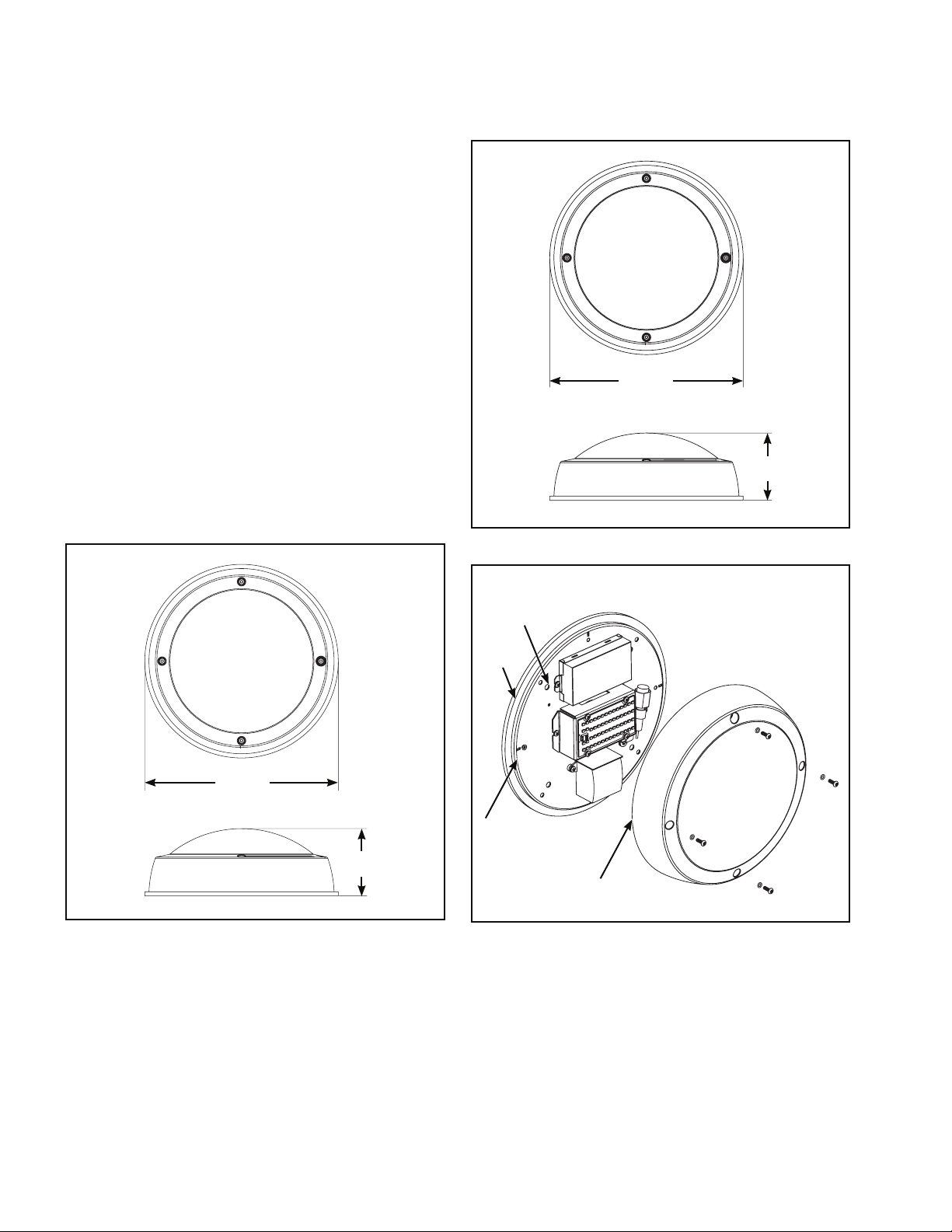
Figure 2. Shallow Unit
ø11.44
(290.53)
5.60
(142.24)
Figure 1. Flat Unit
ø11.50
(292.10)
4.00
(101.60)
Clearance
Hole for
1/4” Bolt
Gasket
Back - Plate
Lens
Figure 3. Flat Unit Installation
2
Page 3

COOPER LIGHTING SOLUTIONS IB519021EN Installation instructions
Installation Instruc tions - TR11 LED
CAUTION
Do not touch LEDs on fixture, care must be taken to not
come in contact with LED board(s) or connector(s) during
fixture installation.
5. Align fixture without lens to four mount holes. For wall
mounted, note that the driver will be oriented at the
top as shown in (Figure 4). Tighten all four mounting
fasteners sufficiently to compress housing into gasket.
ote:N If mounting surface is uneven or rough, it will
be necessary to caulk around fixture to provide
water tight seal.
6. Replace the lens by aligning (3) lens pins and mounting
plate slots. On the plate, they should be located at the
3, 9 and 12 O’clock positions. Use O-ring (Supplied)
with all four screws.
ote:N If using eyelid option, the lens should be
attached first using the shorter screws at the
“12 and 6 O’clock” position and fastened
securely. The eyelid should then be installed
with the longer screws at the “3 and 9 O’clock”
positions and fastened securely. If using Eyelid
option make sure the eyelid is also in the “UP”
position. (Figure 5) Do not over torque screws
during installation of lens.
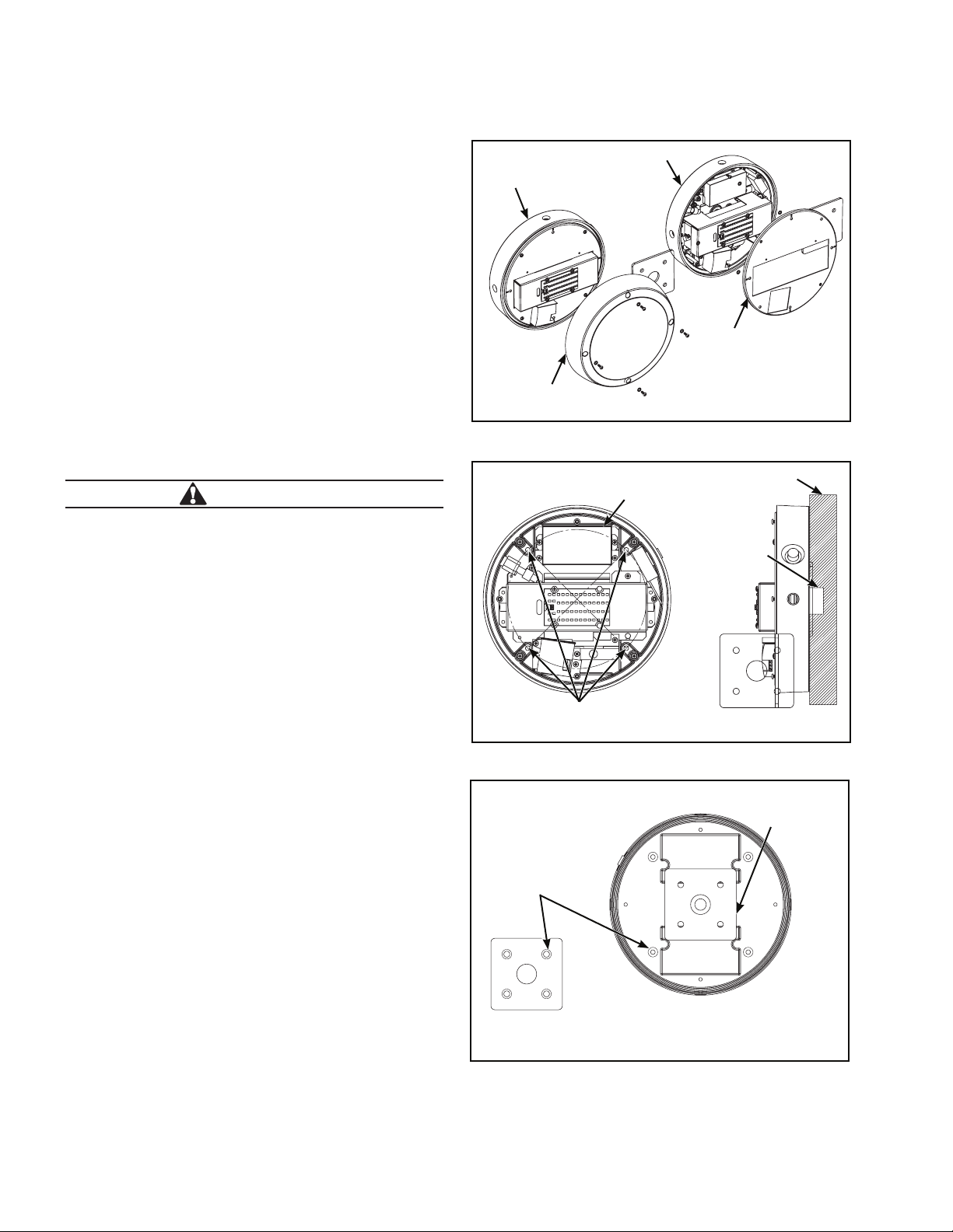
Driver will
Gasket
Back - Plate
Diagonal Mounting Holes
always be on
top
Figure 4. Flat Unit Installation
Clearance
Hole for
1/4” Bolt
Junction
Box
Wall
Figure 5. Eyelid (Downlight Installation)
3
Page 4
COOPER LIGHTING SOLUTIONS IB519021EN Installation instructions
Installation Instruc tions - TR11 LED
Shallow Cast Unit Installation
1. Remove lens, using a TORX T20 center pin reject
screwdriver.
2. Remove back plate using Philips screwdriver.
3. Select the correct type fasteners to use for the
mounting surface, 1/4” nominal diameter (not supplied).
4. Center cast housing on flat smooth ceiling or wall over
junction box. Use cast housing as a template to layout
fastener locations. (Figure 7.)
5. Remove the four donut gaskets from the supplied
square gasket set. Peel the backing from each of the
four donut gaskets and apply them to the back side of
the cast housing at each of the four mounting holes
(gasket has adhesive on one side). Use the remaining
gasket square to seal cast housing to J-Box.
6. Connect fixture wires to the proper supply wires and
place in junction box. Minimum 90 deg. supply wire
required. Ground fixture with wire provided.
CAUTION
Do not touch LEDs on fixture, care must be taken to not
come in contact with LED bar(s) or connector(s) during
fixture installation.
7. Align fixture without lens to four mount holes. For wall
mounted, note the driver will be oriented at the top as
shown in (Figure 7). Tighten all four mounting fasteners
sufficiently to compress housing into gasket.
ote:N If mounting surface is uneven or rough, it will
be necessary to caulk around fixture to provide
water tight seal.
8. Replace the back plate which was removed in step 2.
Replace the lens by aligning (3) lens pins and mounting
plate slots. On the plate, they should be located at the
3,9 and 12 O’clock” positions. Use ‘O’ ring (Supplied)
with all four screws.
ote:N If using eyelid option, the lens should be
attached first using the shorter screws at the
“12 and 6 O’clock” position and fastened
securely. The eyelid should then be installed
with the longer screws at the “3 and 9 O’clock”
positions and fastened securely. If using Eyelid
option make sure the eyelid is also in the “UP”
position. (Figure.5) Do not over-torque screws
during installation of lens.
Shallow Casting
Shallow Casting
Lens
Figure 6. Shallow Cast Unit Installation
Driver will always
be on top
Junction Box
Diagonal Mounting Holes
Figure 7. Shallow Cast Unit Installation
Donut Gasket
Back-Plate
Wall
Square Gasket
Mounting
Maintenance: Verify that the power is OFF.
Lens panel should be cleaned on a regular schedule (6 to 12
month intervals based on local conditions).
4
Figure 8. Shallow Cast Gasket Location
Page 5
COOPER LIGHTING SOLUTIONS IB519021EN
Instr uctions d’installation
Instruct ions d’installation - DEL TR11
AVERTISSEMENT
Assurez-vous que l'alimentation électrique soit HORS
TENSION avant de commencer l'installation ou de
procéder à l'entretien. Risque d'incendie et de décharge
électrique. Si vous n’êtes pas qualifié, consultez un
électricien.
RISQUE DE DÉCHARGE ÉLECTRIQUE - Débranchez
la source d'alimentation en enlevant le fusible ou
en déclenchant le disjoncteur avant l'installation ou
l'entretien.
RISQUE DE BRÛLURE - Débranchez la source
d'alimentation et laissez refroidir le luminaire avant
de procéder à son entretien.
IMPORTANT: À lire avant l'installation du luminaire. Conservez pour consultation ultérieure.
GÉNÉRALITÉS: Dès sa réception, examinez entièrement le luminaire pour déceler tous les dommages occasionnés par le
transport, lesquels devraient être signalés au transporteur livreur. Comparez la description cataloguée sur le bordereau de
marchandises avec l'étiquette du luminaire sur le boîtier pour confirmer la réception de la bonne marchandise.
SÉCURITÉ: Ce luminaire doit être câblé conformément au Code National de l'Électricité et à tous les codes et règlements
locaux en vigueur. Une mise à la terre adéquate est requise afin d'assurer votre sécurité personnelle. Observez
attentivement la procédure de mise à la terre dans la section sur l'installation.
NETTOYAGE: On peut nettoyer le réflecteur et la lentille à l'aide d'un chiffon non abrasif et de détergent doux (par ex.:
nettoyant 409). Le nettoyage de la lentille doit être effectué à température ambiante et sans être directement exposé à la
lumière du soleil. Pour retirer les traces de peinture, de rouge à lèvres, de marqueur, etc., les solvants suivants peuvent être
utilisés.
RECOMMANDÉ:
1. Une solution de trois (3) parties d'alcool, une (1) partie de TOLUOL.
OU
2. Quatre (4) parties d'alcool, une (1) partie de méthyléthylcétone (MEC). Également sûr, mais moins efficace: Naphte,
butylcellosolve, kérosène.
RISQUE DE BLESSURES - Ce luminaire peut
s'endommager s'il n'est pas installé correctement
ou s'il est instable.
REMARQUE: Ces instructions ne prétendent pas couvrir
tous les détails ou toutes les variations de l'équipement,
des procédures ou des processus décrits et ne fournissent
pas de directives qui tiennent compte de toutes les
éventualités possibles durant l'installation, le fonctionnement
ou l'entretien. Si vous désirez obtenir de l'information
supplémentaire pour résoudre un problème qui n'est pas
suffisamment traité, communiquez avec votre représentant
le plus proche. Les caractéristiques de conception et les
dimensions sont indiquées sous réserve de modifications.
INSTALLATION
Identifier quel type de luminaire est installé. Ceci vous
guidera à travers le reste des directives d’installation.
Consultez chacune des sections pour chaque type de
luminaire en particulier. Il y a deux modèles de luminaires
(plats et peu profonds) la profondeur de protubérance
à partir de la surface d'installation (voir les schémas
ci-dessous). Commencez par retirer le module de la
lentille à l'aide d'un tournevis Torx T20 pour les vis avec
goupille centrale. (Tournevis vendu séparément, nombre de
catalogue Cooper Lighting Solutions VRSD ou mèche VRSB
de 6,35mm (1/4 po).
Installation du modèle plat
1. Retirez la lentille, à l'aide d'un tournevis TORX T20 pour
retirer une vis à goupille centrale.
2. Choisissez les fixations appropriées à la surface de
montage, diamètre nominal 6,35mm (1/4 po) (non
fournies).
Figure 1 Modèle plat
ø11,50
(292,10)
4,00
(101,60)
5
Page 6

COOPER LIGHTING SOLUTIONS
IB519021EN Instruc tions d’installation
Instruct ions d’installation - DEL TR11
3. Centrez la plaque centrale sur un plafond ou mur plat
et lisse au-dessus de la boîte de jonction. Utilisez la
plaque centrale comme modèle pour disposer les
emplacements des fixations. (Figure 4).
4. Raccordez les fils du luminaire aux fils d'alimentation
appropriés et mettez-les dans la boîte de jonction.
Des câbles d'alimentation de 90°C minimum sont
nécessaires. Mettez le luminaire à la terre à l'aide du fil
fourni.
MISE EN GARDE
Ne touchez pas les DEL sur le luminaire, faites attention
à ne pas entrer en contact avec la/les plaque(s) ou
connecteur(s) pendant l'installation du luminaire.
Trou de dégagement pour
boulon de 6,35mm (1/4po)
Joint
5. Alignez le luminaire sans la lentille aux quatre trous de
montage. Pour une installation murale, notez que le
tournevis sera orienté au sommet, tel qu'illustré à la
(figure 4). Serrez les quatre fixations de montage de
manière suffisante pour comprimer le boîtier au joint.
emarque:R Si la surface de montage est accidentée
ou rugueuse, vous devrez calfeutrer autour
du luminaire pour assurer un joint étanche.
ø11,44
(290,53)
5,60
(142,24)
Plaque dorsale
Lentille
Figure 3 Installation du modèle plat
Plaque
dorsale
Le tournevis
Joint
doit toujours
être au sommet
Trous d'installation en diagonale
Trou de
dégagement
pour boulon
de 6,35mm
(1/4po)
Mur
Boîte de
jonction
Figure 2 Modèle à boîtier peu profond
6
Figure 4 Installation du modèle plat
Page 7

COOPER LIGHTING SOLUTIONS IB519021EN
Instr uctions d’installation
Instruct ions d’installation - DEL TR11
6. Remettez la lentille en place en alignant (3) goupilles
de lentille et les fentes de la plaque de montage. Sur
la plaque, doivent être disposées à 3, 9 et 12 heures.
Installez le joint torique (fourni) avec les quatre vis.
emarque:R l'aide des vis plus courtes 12 et 6
heures. La «paupière» doit ensuite être
solidement fixée à l'aide des vis plus
longues 3 et 9 heures. Si vous utilisez
l'option «paupière», assurez-vous que
celle-ci est également en position relevée
(Figure 5). Ne serrez pas trop les vis lors
de l'installation de la lentille.
Installation du modèle à boîtier moulé peu profond
1. Retirez la lentille, à l'aide d'un tournevis TORX T20 pour
retirer une vis à goupille centrale.
2. Retirez la plaque dorsale à l'aide d'un tournevis
cruciforme.
3. Choisissez les fixations appropriées à la surface de
montage, diamètre nominal 6,35mm (1/4 po) (non
fournies).
4. Centrez le boîtier moulé sur un plafond ou mur plat et
lisse au-dessus de la boîte de jonction. Utilisez le boîtier
moulé comme modèle pour disposer les emplacements
des fixations. (Figure7.)
5. Retirez les quatre rondelles d'étanchéité des quatre
ensembles de joints carrés fournis. Décollez la pellicule
protectrice de l'arrière de cha rondelle d'étanchéité et
appliquez-les derrière le boîtier moulé au niveau des
quatre trous de fixation (le joint d'étanchéité est adhésif
d'un côté). Utilisez le joint carré restant pour sceller le
boîtier moulé à la boîte de jonction.
6. Raccordez les fils du luminaire aux fils d'alimentation
appropriés et mettez-les dans la boîte de jonction.
Des câbles d'alimentation de 90°C minimum sont
nécessaires. Mettez le luminaire à la terre à l'aide du fil
fourni.
Figure 5 Paupière (installation de plafonnier)
Moulage peu profond
Moulage peu profond
Plaque dorsale
Lentille
Figure 6 Installation du modèle à boîtier moulé peu
profond
MISE EN GARDE
Ne touchez pas les DEL sur le luminaire, faites attention
à ne pas entrer en contact avec la/les barre(s) ou
connecteur(s) pendant l'installation du luminaire.
7. Alignez le luminaire sans la lentille aux quatre trous de
montage. Pour une installation murale, notez que le
tournevis sera orienté au sommet, tel qu'illustré à la
(figure 7). Serrez les quatre fixations de montage de
manière suffisante pour comprimer le boîtier au joint.
emarque:R Si la surface de montage est accidentée ou
rugueuse, vous devrez calfeutrer autour du
luminaire pour assurer un joint étanche.
Le tournevis doit
toujours être au
sommet
Boîte de jonction
Trous d'installation en diagonale
Mur
Figure 7 Installation du modèle à boîtier moulé peu
profond
7
Page 8

COOPER LIGHTING SOLUTIONS
IB519021EN Instruc tions d’installation
Instruct ions d’installation - DEL TR11
8. Replacez la plaque dorsale retirée à l'étape 2. Remettez
la lentille en place en alignant (3) goupilles de lentille et
les fentes de la plaque de montage. Sur la plaque, elles
doivent être disposées à 3, 9 et 12 heures. Installez le
joint torique (fourni) avec les quatre vis.
emarque:R Lorsque l'option «paupière» est utilisée,
la lentille doit être solidement fixée
d'abord à l'aide des vis plus courtes12
et 6 heures. La «paupière» doit ensuite
être solidement fixée à l'aide des vis plus
longues 3 et 9 heures. Si vous utilisez
l'option «paupière», assurez-vous que
celle-ci est également en position relevée
(figure 5). Ne serrez pas trop les vis lors de
l'installation de la lentille.
Montage du
joint carré
Rondelle
d'étanchéité
Entretien : Assurez-vous que l'alimentation électrique
est HORS TENSION.
Le panneau de la lentille doit être nettoyé régulièrement (à
intervalles de 6 à 12 mois selon les conditions locales).
Figure 8 Emplacement du boîtier moulé peu profond
8
Page 9

COOPER LIGHTING SOLUTIONS
IB519021EN Instr ucciones de instalación
Instrucciones de instalación - LED TR11
ADVERTENCIA
Asegúrese de que la alimentación esté desconectada
antes de comenzar la instalación o intentar realizar el
mantenimiento. Riesgo de incendio y descarga eléctrica.
Si no está cualificado, consulte con un electricista.
RIESGO DE DESCARGA ELÉCTRICA: Desconecte
la alimentación en el disyuntor o fusible antes de
instalar o realizar tareas de mantenimiento.
RIESGO DE QUEMADURAS: Desconecte la
alimentación y espere a que se enfríe la luminaria
antes de realizar tareas de mantenimiento.
IMPORTANTE: Lea antes de instalar la luminaria. Conserve estas instrucciones para tenerlas como referencia futura.
GENERAL: Al recibir la luminaria, controle en detalle que no se haya dañado durante su transporte. Si hubiera daños, informe
al transportista de la entrega. Compare la descripción del catálogo en el recibo de envío con la etiqueta de la luminaria sobre
la cubierta para asegurarse de haber recibido la mercadería correcta.
SEGURIDAD: Esta luminaria debe cablearse de conformidad con el Código Eléctrico Nacional y las ordenanzas y los códigos
locales aplicables. Se requiere una correcta conexión a tierra para garantizar la seguridad personal. Consulte atentamente el
procedimiento de conexión a tierra en la sección de instalación.
LIMPIEZA: Puede limpiar el reflector y la lente con cualquier paño no abrasivo y un detergente suave (como el 409 Cleaner).
Se debe hacer la limpieza de la lente a temperatura ambiente y fuera de la luz solar directa. Para quitar pintura, lápiz labial,
marcador, etc., pueden utilizarse los siguientes solventes:
RECOMENDADOS:
9. Una solución de tres (3) partes de alcohol y una (1) parte de TOLUENO.
O:
10. Cuatro (4) partes de alcohol y una (1) parte de metiletilcetona (MEK). También seguros, pero menos eficaces: Nafta, éter
monobutílico de etilenglicol y keroseno.
RIESGO DE LESIONES FÍSICAS: La luminaria puede
dañarse o convertirse en un objeto inestable si no
se la instala correctamente.
AVISO: Por medio de estas instrucciones, no se pretende
cubrir todos los detalles ni todas las variaciones en el
equipamiento, procedimiento o proceso descritos, ni aportar
directivas para tratar cualquier posible contingencia durante
la instalación, la operación o el mantenimiento. Cuando
se requiera mayor información para tratar un problema
que no está cubierto suficientemente para los fines del
usuario, contacte a su representante más cercano. Las
especificaciones de diseño y las dimensiones de la luminaria
quedan sujetas a modificaciones sin previo aviso.
INSTALACIÓN
Identifique qué tipo de unidad se instalará. Esto lo ayudará
con el resto de las instrucciones de instalación. Consulte
cada sección para cada tipo específico de unidad. Hay dos
estilos de unidades (planas y poco profundas), según lo
determina la distancia que sobresale desde la superficie
de montaje (vea las figuras a continuación). Comience
por quitar la unidad de la lente con un destornillador Torx
T20 para tornillos con cabeza de forma estrellada. (El
destornillador se vende por separado, número de catálogo
Cooper Lighting Solutions VRSD o broca VRSB de 1/4”.)
Instalación de la unidad plana
1. Retire la lente con un destornillador TORX T20 con
cabeza de forma estrellada.
2. Seleccione tipos de tornillos apropiados para utilizar en
la superficie de montaje, de diámetro nominal de 1/4"
(no incluidos).
3. Centre la placa de montaje en un techo o pared planos
por encima de la caja de derivación. Utilice la placa de
montaje como plantilla para presentar las ubicaciones
de los tornillos. (Figura 4.)
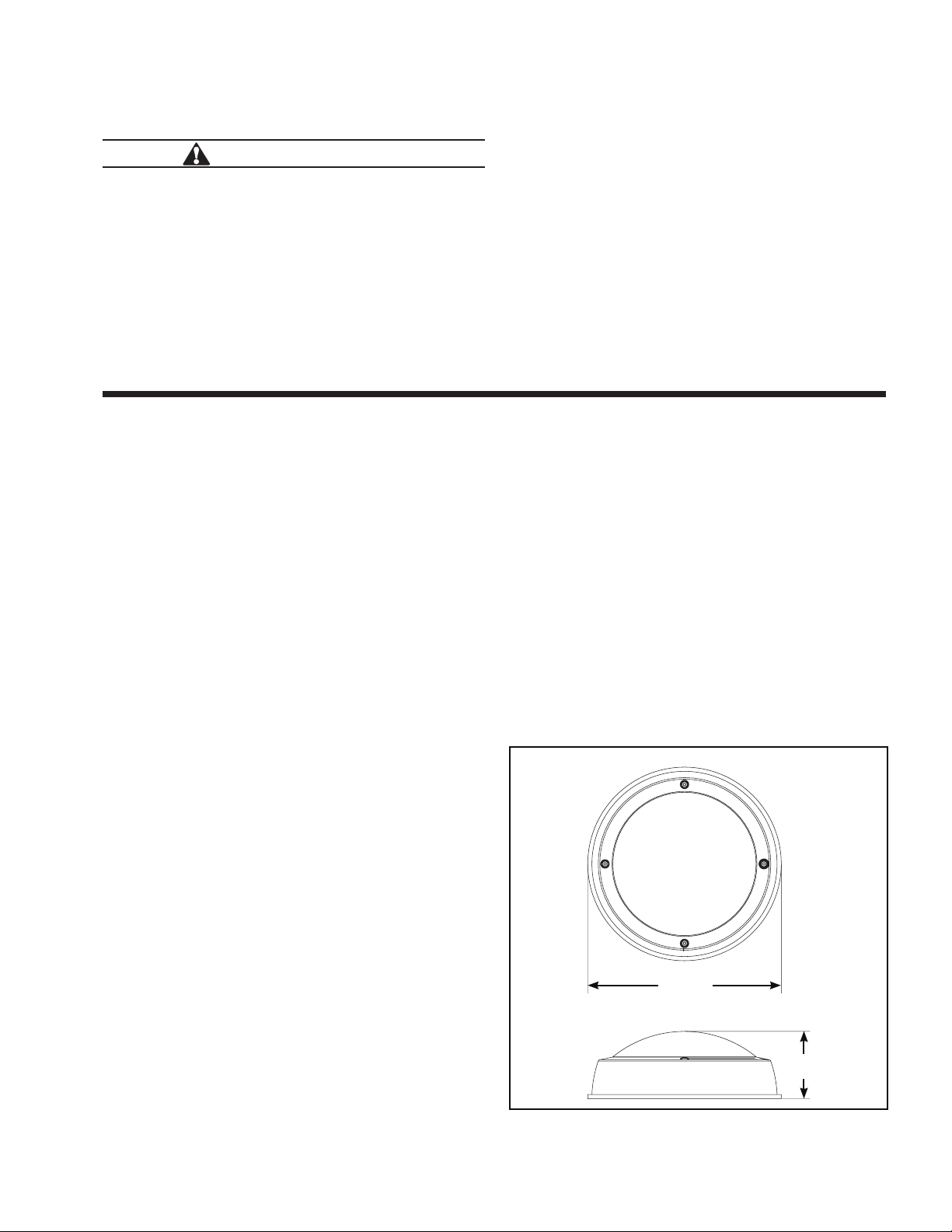
Figura 1. Unidad plana
ø11,50
(292.10)
4,00
(101,60)
9
Page 10

COOPER LIGHTING SOLUTIONS IB519021EN
Instr ucciones de instalación
Instrucciones de instalación - LED TR11
4. Conecte los cables de la luminaria a los cables de
alimentación correspondientes y colóquelos en la caja
de derivación. Necesitará un cable de alimentación de
90 grados como mínimo. Conecte la luminaria a tierra
con el cable suministrado.
Orificio de
paso para el
tornillo de 1/4”
PRECAUCIÓN
No toque los LED en la luminaria. Debe tenerse cuidado
de no tocar los tableros LED ni los conectores durante la
instalación de la luminaria.
5. Alinee la luminaria sin la lente con los cuatro orificios
de montaje. Para el montaje en pared, tenga en
cuenta que el controlador estará orientado hacia arriba
como se muestra (Figura 4). Ajuste los cuatro tornillos
de montaje lo suficiente como para comprimir el
alojamiento contra la junta.
ota:N Si la superficie de montaje es despareja
o áspera, será necesario colocar sellador
alrededor de la luminaria para generar un sellado
hermético.
Junta
Placa trasera
Lente
Figura 3. Instalación de la unidad plana
El controlador
Placa
trasera
Junta
siempre estará
en la parte
superior
Orificio de
paso para el
tornillo de
1/4”
Caja de
derivación
Pared
ø11,44
(290.53)
Figura 2. Unidad superficial
10
5.60
(142,24)
Orificios de montaje en diagonal
Figura 4. Instalación de la unidad plana
Page 11

COOPER LIGHTING SOLUTIONS
IB519021EN Instr ucciones de instalación
Instrucciones de instalación - LED TR11
6. Vuelva a colocar la lente alineando las (3) clavijas con
las ranuras de la placa de montaje. Debe colocarlos
sobre la placa en las posiciones de las 3, 9 y 12, como
si fuera un reloj. Use la junta tórica (incluida) con los
cuatro tornillos.
ota:N Si utiliza el modelo con reborde, debe sujetar
primero la lente con los tornillos más cortos en
la posición de las 12 y las 6 en punto, debiendo
fijarlos firmemente. Entonces deberá instalar
el reborde con los tornillos más largos en las
posiciones de las 3 y las 9 en punto, y ajustarlos
firmemente. Si utiliza la opción con reborde,
asegúrese de que el reborde esté en posición
hacia arriba. (Figura 5) No ajuste excesivamente
los tornillos durante la instalación de la lente.
Instalación de la unidad de empotramiento en
superficie
1. Retire la lente con un destornillador TORX T20 con
cabeza de forma estrellada.
2. Retire la placa trasera con un destornillador Phillips.
3. Seleccione tipos de tornillos apropiados para utilizar en
la superficie de montaje, de diámetro nominal de 1/4"
(no incluidos).
4. Centre el alojamiento de empotramiento en un techo o
pared planos por encima de la caja de derivación. Utilice
dicho alojamiento como una plantilla para presentar las
ubicaciones de los tornillos. (Figura 7.)
5. Retire las cuatro juntas en forma de rosquilla del juego
de juntas cuadradas incluido. Retire el reverso de
cada una de las cuatro juntas en forma de rosquilla y
colóquelas en el lado trasero del alojamiento empotrado
en cada uno de los cuatro orificios de montaje (la
junta tiene adhesivo en uno de los lados). Use la junta
cuadrada restante para sellar el alojamiento a la caja de
derivación.
6. Conecte los cables de la luminaria a los cables de
alimentación correspondientes y colóquelos en la caja
de derivación. Necesitará un cable de alimentación de
90 grados como mínimo. Conecte la luminaria a tierra
con el cable suministrado.
Figura 5. Reborde (instalación con iluminación hacia
abajo)
Empotramiento en superficie
Empotramiento en superficie
Placa trasera
Lente
Figura 6. Instalación de la unidad de empotramiento en
superficie
Le tournevis doit toujours être au sommet
Mur
No toque los LED en la luminaria. Debe tenerse cuidado de
no tocar la(s) barra(s) de LED o el o los conectores durante
la instalación de la luminaria.
7. Alinee la luminaria sin la lente con los cuatro orificios
de montaje. Para el montaje en pared, tenga en
cuenta que el controlador estará orientado hacia arriba
como se muestra (Figura 7). Ajuste los cuatro tornillos
de montaje lo suficiente como para comprimir el
alojamiento contra la junta.
ota:N Si la superficie de montaje es despareja
PRECAUCIÓN
o áspera, será necesario colocar sellador
alrededor de la luminaria para generar un sellado
hermético.
Boîte de jonction
Trous d'installation en diagonale
Figure 7 Installation du modèle à boîtier moulé peu
profond
11
Page 12

COOPER LIGHTING SOLUTIONS IB519021EN
Instr ucciones de instalación
Instrucciones de instalación - LED TR11
8. Coloque nuevamente la placa trasera que retiró en
el paso 2. Vuelva a colocar la lente alineando las (3)
clavijas con las ranuras de la placa de montaje. Debe
colocarlos sobre la placa en las posiciones de las 3, 9 y
12, como si fuera un reloj. Use la junta tórica (incluida)
con los cuatro tornillos.
ota:N Si utiliza el modelo con reborde, debe sujetar
primero la lente con los tornillos más cortos en
la posición de las 12 y las 6 en punto, debiendo
fijarlos firmemente. Entonces deberá instalar
el reborde con los tornillos más largos en las
posiciones de las 3 y las 9 en punto, y ajustarlos
firmemente. Si utiliza la opción con reborde,
asegúrese de que el reborde esté en posición
hacia arriba. (Figura 5) No ajuste excesivamente
los tornillos durante la instalación de la lente.
Montaje con
junta cuadrada
Junta redonda
Mantenimiento: Verifique que la alimentación esté
desconectada.
Se debe limpiar el panel de la lente en forma periódica (cada
6-12 meses según las condiciones locales).
Figura 8. Ubicación de la junta de empotramiento
superficial
12
Page 13

131415
Page 14

Page 15

Page 16

Warranties and Limitation of Liability
Please refer to www.cooperlighting.com for our terms and conditions.
Garanties et limitation de responsabilité
Veuillez consulter le site www.cooperlighting.com pour obtenir les conditions générales.
Garantías y Limitación de Responsabilidad
Visite www.cooperlighting.com para conocer nuestros términos y condiciones.
Cooper Lighting Solutions
121 Highway 74 South
1
Peachtree City, GA 30269
P:770-486-4800
www.cooperlighting.com
© 2020 Cooper Lighting Solutions
All Rights Reserved
Printed in USA
Imprimé aux États-Unis
Impreso en los EE. UU.
Publication No. IB519021EN
May 30, 2016
Cooper Lighting Solutions is a
registered
All trademarks are property
of their respective owners.
Cooper Lighting Solutions est une
marque de commerce déposée. Toutes
les autres marques de commerce sont
la propriété de leur propriétaire
respectif.
Cooper Lighting Solutions es una
marca comercial registrada. Todas las
marcas comerciales son propiedad de
sus respectivos propietarios.
trademark.
Product availability, specifications,
and compliances
change without notice
La disponibilité du produit, les
spécifications et les conformités
peuvent être modifiées sans préavis
La disponibilidad de productos, las
especificaciones y los cumplimientos
están sujetos a cambio sin previo
aviso
are subject to
 Loading...