

Page 1
INS #
Brand Logo
reversed out of
black
INS #
IB506004EN
Installation Instructions - NFFLD-L/UFLD-L
Instructions d’installation - NFFLD-L/UFLD-L
Instrucciones de instalación - NFFLD-L/UFLD-L
WARNING
Make certain power is OFF before starting installation
or attempting any maintenance.
WARNING
Risk of fire/electric shock. If not qualified, consult an
electrician.
WARNING
Risk of Electric Shock – Disconnect power at fuse or
circuit breaker before installing or servicing.
WARNING
Risk of Personal Injury – Fixture may become damaged
and/or unstable if not installed properly.
Do not mount luminaire within 6” of a
combustible surface.
Do not handle luminaire by the glass. Do not
touch LEDs.
IMPORTANT: Read carefully before installing fixture. Retain for future reference.
GENERAL: Upon receipt of the fixture, thoroughly inspect for any freight damage which should be brought to the
attention of the delivery carrier. Compare the catalog description listed on the packing slip with the fixture label on the
housing to assure you have received the correct material.
SAFETY: This fixture must be wired in accordance with the National Electrical Code and applicable local codes and
ordinances. Proper grounding is required to insure personal safety. Carefully observe grounding procedure under
installation section.
APPLICATIONS: This lighting fixture is designed for outdoor lighting services, and should not be used in area of limited
ventilation or inside high ambient temperature enclosures. It must be stored in a dry location prior to installation. Do not
expose lighting fixture to rain, dust or other environmental conditions prior to installation and insertion of photocontrol
or shorting cap (if so equipped). Do not install the fixture near combustible materials or locate next to airflow
blocking surfaces within 6 inches. Best results will be obtained if installed and maintained according to the following
recommendations.
Risk of Burn – Disconnect power and allow fixture to
cool before servicing.
ote:N These instructions do not claim to cover all
details or variations in the equipment, procedure,
or process described, nor to provide directions
for meeting every possible contingency during
installation, operation or maintenance. When
additional information is desired to satisfy a
problem not covered sufficiently for user’s purpose,
please contact your nearest representative.
ote:N This lighting fixture has been shipped complete
with one of several mounting options. Please follow
the installation instructions specific to the catalog
part that you ordered.
ote:N Care must be taken not to set lighting fixture down
on optical lenses or lift the fixture in the lens area.
ote:N Specifications and dimensions subject to change
without notice.
WARNING
Page 2
COOPER LIGHTING SOLUTIONS IB506004EN Installation instructions
Installation Instruc tions - NFFLD-L/UFLD-L
INSTALLATION
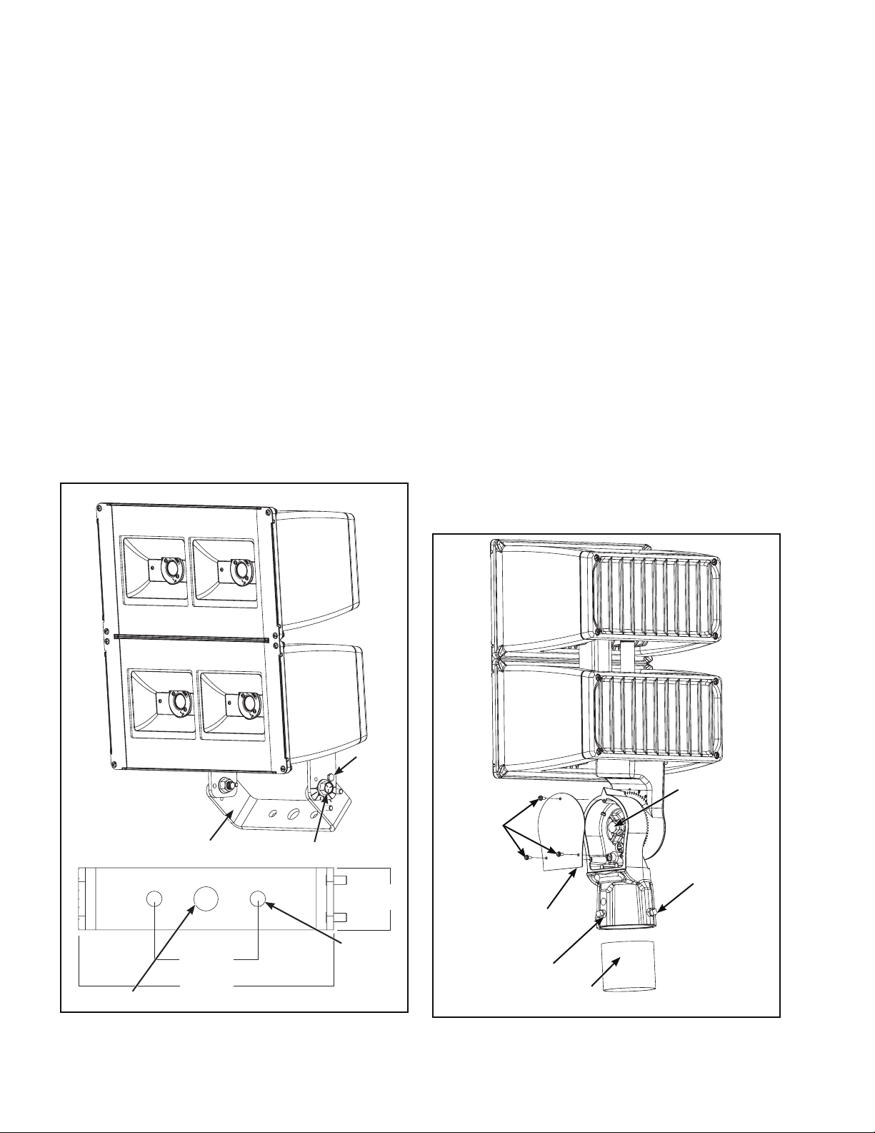
Trunnion Mounting (Figure 1.)
Tools Required
Torque wrench (ft-lbs), torque wrench (in-lbs), 3/4" socket
and 7/16” socket.
1. Mount luminaire to surface using the hole pattern
provided on the trunnion bracket.
ote:N Hardware recommended: 1/2" diameter bolt x 1-1/2"
long. (Supplied by others)
2. Loosen but do not remove (2) center bolts and (1) set
screw. (Figure 1.)
3. Rotate luminaire to desired aiming position and tighten
center bolts to 75 ft-lbs.
4. Tighten set screw to 30 in-lbs.
5. Refer to wiring diagrams for power connection.
(Figure 4.)
Slipfitter Mounting (Figure 2.)
Tools Required
Torque wrench (ft-lbs), torque wrench (in-lbs), 3/4” socket,
3/8” allen drive, #2 phillips head screw driver and
3/8” square nut driver.
1. If angle adjustment is required please proceed to
step 2, if not skip to step 5.
2. Remove (3) cover plate screws and cover plate with #2
Philips screwdriver. (Figure 2.)
3. To change luminaire tilt angle, loosen center bolt, rotate
fixture to the desired angle, and tighten center bolt to
30 ft-lbs.
4. Replace cover plate and tighten cover plate screws with
#2 Philips screwdriver to 15 in-lbs.
5. Make wiring connections per wiring diagram and place
connections into pole or mounting bracket. (Figure 4.)
6. Loosen (4) set screws and slide the slipfitter onto pole
or mounting bracket.
7. Position luminaire into the desired direction and tighten
(4) set screws to 10 ft-lbs. (Figure 2.)
8. Tighten lock nuts to 15 ft-lbs. (Figure 2.)
Set
Screw
7/8” (23mm)
Trunnion Bracket
3-13/16”
(97mm)
9-5/16”
(237mm)
Center Bolt
2-5/16”
(59mm)
(2) 9/16”
(15mm)
Figure 1.
2
Center Bolt
Cover Plate
Screws (3)
Set Screws (4)
Cover Plate
Lock Nuts (4)
Pole
Figure 2.
Page 3
COOPER LIGHTING SOLUTIONS IB506004EN Installation instructions
Installation Instruc tions - NFFLD-L/UFLD-L
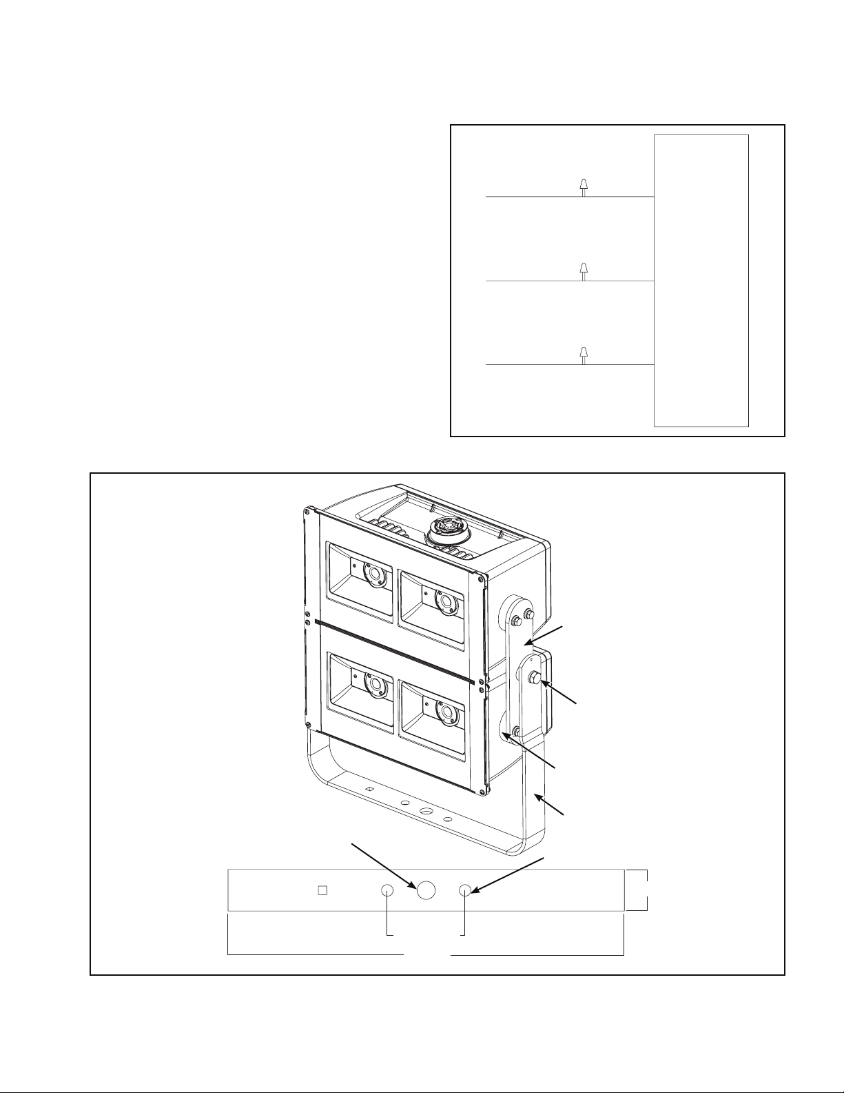
Yoke Mounting (Figure 3.)
Tools Required
Torque wrench (ft-lbs) and 3/4” socket.
1. Mount luminaire to surface using the hole pattern
provided on the yoke.
ote:N Hardware recommended 1/2" diameter bolt x 1-1/2"
long. (Supplied by others)
2. Loosen but do not remove (2) center bolts. (Figure 3.)
3. Rotate luminaire to desired aiming position and tighten
center bolts to 75 ft-lbs.
4. Refer to wiring diagrams for power connection.
(Figure 4.)
Figure 4.
(+) Line
(-) Common
Ground
Black
White
Green
Fixture
Figure 3.
7/8”
(23mm)
Yoke Connector
Center Bolt
Mounting Block
Yoke Bracket
(2) 9/16” (15mm)
2” (51mm)
3-13/16”
(97mm)
19”
(485mm)
3
Page 4
COOPER LIGHTING SOLUTIONS IB506004EN Installation instructions
Installation Instruc tions - NFFLD-L/UFLD-L
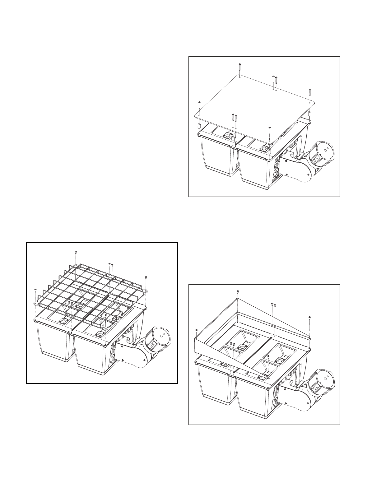
Accessories
Tools Required
Phillips screwdriver.
Wire Guard (Figure 5.)
1. Loosen and remove the existing (8) 10-24 Philips head
screws on the face of the fixture and retain for future
reference.
2. Align wire guard on top of lens clips matching the four
existing holes. (Figure 5.)
3. Retighten (8) 10-24 Philips head screws from step 1, to
the face of the fixture.
4. To remove wire guard follow steps 1-3 in reverse order.
Vandal Shield (Figure 6.)
1. Loosen and remove the existing (8) 10-24 Philips head
screws on the face of the fixture.
2. Align (8) 7/8” long spacers with existing holes.
3. Use (8) 10-24 x 1-1/2” screws to secure vandal shield
on top of fixture. (Figure 6.)
4. To remove vandal shield follow steps 1-3 in reverse
order.
Figure 6.
Visor (Figure 7.)
1. Loosen and remove the existing (4) 10-24 Philips head
screws on the face of the fixture and retain for future
reference.
2. Align visor on top of lens clips matching the (4) existing
holes. (Figure 7.)
3. Use the existing (4) 10-24 Philips head screws to
secure visor.
4. To remove visor follow steps 1-3 in reverse order.
Figure 5.
4
Figure 7.
Page 5
COOPER LIGHTING SOLUTIONS I
B506004EN Instru ctions d’installation
Instructions d’installation - NFFLD-L/UFLD-L
AVERTISSEMENT
Assurez-vous que l'alimentation électrique soit HORS
TENSION avant de commencer l'installation ou de
procéder à l'entretien.
AVERTISSEMENT
Risque de brûlures – Mettez l’alimentation électrique
hors tension et laissez refroidir le luminaire avant
l'entretien.
AVERTISSEMENT
Risque d'incendie et de décharge électrique. Si vous
n’êtes pas qualifié, consultez un électricien.
AVERTISSEMENT
Risque de décharge électrique – Mettez l’alimentation
électrique hors tension en enlevant le fusible ou en
déclenchant le disjoncteur avant l'installation ou
l'entretien.
AVERTISSEMENT
Risques de blessures – Le luminaire peut être
endommagé ou instable s'il n'est pas installé
correctement.
N'installez pas le luminaire à moins de 15 cm (6 po)
d'une surface combustible.
Ne manipulez pas le luminaire par le verre. Ne
touchez pas les DEL.
IMPORTANT: Lisez attentivement avant d'installer le luminaire. Conservez pour consultation ultérieure.
GÉNÉRALITÉS: Inspectez minutieusement le luminaire dès sa réception pour déceler les dommages occasionnés par le
transport, lesquels devront être signalés au transporteur. Comparez la description du catalogue indiquée sur le bordereau
d'expédition avec l'étiquette du luminaire située sur le boîtier pour vous assurer qu'elle correspond au luminaire commandé.
SÉCURITÉ: Ce luminaire doit être câblé conformément au Code National de l'Électricité et à tous les codes et règlements
locaux en vigueur. Une mise à la terre adéquate est requise afin d'assurer votre sécurité personnelle. Observez
attentivement la procédure de mise à la terre dans la section sur l'installation.
APPLICATIONS: Ce luminaire a été conçu pour l'éclairage extérieur et ne doit pas être utilisé dans un endroit peu ventilé ou
dans une enceinte à haute température ambiante. Il doit être entreposé dans un endroit sec jusqu'à l'installation. N'exposez
pas le luminaire à la pluie, à la poussière ni à toute autre condition environnementale avant de procéder à l'installation et à
l'insertion de la cellule photoélectrique ou du capuchon de mise en court-circuit (si le luminaire en est muni). N'installez pas
le luminaire près de matériaux combustibles et ne le placez pas à proximité de surfaces bloquant la circulation de l'air dans
un rayon de 15,2cm (6po). Les résultats seront meilleurs si le luminaire est installé et entretenu selon les recommandations
suivantes.
emarque:R Ces instructions ne prétendent pas couvrir
tous les détails ou toutes les variations de
l'équipement, des procédures ou des processus
décrits et ne fournissent pas de directives qui
tiennent compte de toutes les éventualités
possibles durant l'installation, le fonctionnement
ou l'entretien. Si vous désirez obtenir de
l'information supplémentaire pour résoudre un
problème qui n'est pas suffisamment traité,
communiquez avec votre représentant le plus
proche.
emarque:R Ce luminaire est livré monté avec une des
multiples options de montage spécifiques.
Veuillez suivre les instructions d'installation se
rapportant au modèle que vous avez commandé.
emarque:R Faites attention de ne pas poser le luminaire
côté lentilles optiques vers le bas ou de le
soulever en le prenant par l'emplacement des
lentilles optiques.
emarque:R Les spécifications et dimensions sont indiquées
sous réserve de modifications.
5
Page 6

COOPER LIGHTING SOLUTIONS I
B506004EN Instr uctions d’installation
Instructions d’installation - NFFLD-L/UFLD-L
INSTALLATION
Montage à tourillon (Figure1).
Outillage nécessaire
Clé dynamométrique (pi-lb), clé dynamométrique (po-lb),
douilles de 19,1mm (3/4po) et de 11,1mm (7/16po).
1. Fixez le luminaire à la surface en utilisant le trou au
niveau du support du tourillon.
emarque:R Matériel recommandé: boulon de 12,7mm
(1/2po) de diamètre x 38,1mm (11/2po) de
longueur (non fourni)
2. Desserrez mais ne retirez pas (2) boulons centraux et
(1) vis d'ajustement. (Figure1).
3. Faites pivoter le luminaire jusqu'à la position désirée et
serrez les boulons centraux à 102Nm (75 pi-lb).
4. Serrez la vis d'ajustement à 3,4Nm (30 po-lb).
5. Consultez le schéma de câblage pour le raccordement
de l’alimentation. (Figure4).
Montage sur splitfitter (Figure2).
Outillage nécessaire
Clé dynamométrique (pi-lb), clé dynamométrique (po-lb),
douilles de 19,1mm (3/4po), tournevis à écrous
hexagonaux de 9,5mm (3/8po), tournevis cruciforme n°2
et tournevis à douille carrée de 9,5mm (3/8po).
1. Si un réglage de l'angle est requis, veuillez effectuer
l'étape 2, sinon, passez directement à l'étape 5.
2. Retirez (3) vis de plaque de recouvrement et la plaque
de recouvrement avec un tournevis cruciforme n°2.
(Figure2).
3. Pour changer l'angle d'inclinaison du luminaire,
desserrez le boulon central, faites pivoter le luminaire
de l'angle requis et serrez le boulon central à un couple
de 40,7Nm (30pi-lb).
4. Replacez la plaque de recouvrement et serrez les vis de
la plaque avec un tournevis cruciforme n°2 à un couple
de 1,7Nm (15po-lb).
5. Effectuez les raccordements de câblage tel qu'indiqué
sur le schéma de câblage et introduisez les
branchements à l'intérieur du pôle ou du support de
montage. (Figure4).
Support du tourillon
97mm
(3-13/16
po)
23mm (7/8po)
237mm
(9-5/16po)
Figure 1
6
d'ajustement
Boulon central
59mm
(2-5/16po)
(2) 15mm
(9/16po)
Vis
Boulon central
(3) vis de la
plaque de
recouvrement
(4) vis
d'ajustement
Plaque de
recouvrement
(4) écrous de blocage
Pôle
Figure 2
Page 7

COOPER LIGHTING SOLUTIONS I
B506004EN Instru ctions d’installation
Instructions d’installation - NFFLD-L/UFLD-L
6. Desserrez (4) vis d'ajustement et faites glisser le
splitfitter à l'intérieur du pôle ou du support de
montage.
7. Fixez le luminaire dans la position souhaitée et serrez
(4) vis d'ajustement à un couple de 13,6Nm (10 pi-lb).
(Figure2.)
8. Serrez les écrous de blocage à 20,3Nm (15 pi-lb).
(Figure2).
4. Consultez le schéma de câblage pour le raccordement
de l’alimentation. (Figure4).
(+) Ligne
Noir
Montage sur berceau (Figure3).
Outillage nécessaire
Clé dynamométrique (pi-lb) et douille de 19,1mm (3/4po).
1. Fixez le luminaire à la surface en utilisant le trou au
niveau du berceau.
emarque:R Matériel recommandé: boulon de 12,7mm
(1/2po) de diamètre x 38,1mm (11/2po) de
longueur (non fourni)
2. Desserrez mais ne retirez pas (2) boulons centraux.
(Figure3).
3. Faites pivoter le luminaire jusqu'à la position désirée et
serrez les boulons centraux à 102Nm (75 pi-lb).
Figure 4
(-) Commun
Terre
Connecteur du berceau
Blanc
Vert
Luminaire
Figure 3
23mm
(7/8po)
Boulon central
Bloc de montage
Support du berceau
(2) 15mm (9/16po)
51mm(2po)
97mm
(3-13/16po)
485mm
(19po)
7
Page 8

COOPER LIGHTING SOLUTIONS IB506004EN
Instruc tions d’installation
Instructions d’installation - NFFLD-L/UFLD-L
Accessoires
Outillage nécessaire
Tournevis cruciforme.
Grille de protection (Figure5).
1. Desserrez et retirez les (8) vis hexagonales 10-24 sur la
partie frontale du luminaire et conservez-les pour vous
y référer ultérieurement.
2. Alignez la grille de protection avec les quatre trous de la
partie supérieure de l'attache de la lentille. (Figure5).
3. Resserrez les (8) vis hexagonales 10-24 de l'étape 1 sur
la partie frontale du luminaire.
4. Pour retirer la grille de protection, suivez les étapes 1 à
3 dans l'ordre inverse.
Protection anti-vandalisme (Figure6).
1. Desserrez et retirez les (8) vis hexagonales 10-24 sur la
partie frontale du luminaire.
2. Alignez les (8) entretoises longues de 22,2mm (7/8po)
avec les trous existants.
3. Utilisez les (8) vis 10-24 x 38,1mm (11/2po) pour fixer
fermement la protection anti-vandalisme sur la face
supérieure du luminaire. (Figure6).
4. Pour retirer la protection anti-vandalisme, suivez les
étapes 1 à 3 dans l'ordre inverse.
Figure 6
Visière (Figure7).
1. Desserrez et retirez les (4) vis hexagonales 10-24 sur la
partie frontale du luminaire et conservez-les pour vous
y référer ultérieurement.
2. Alignez la visière avec les (4) trous de la partie
supérieure de l'attache de la lentille. (Figure7).
3. Utilisez les (4) vis hexagonales 10-24 pour fixer
fermement la visière.
4. Pour retirer la visière, suivez les étapes 1 à 3 dans
l'ordre inverse.
Figure 5
8
Figure 7
Page 9

COOPER LIGHTING SOLUTIONS
IB506004EN Instrucciones de instalación
Instrucciones de instalación - NFFLD-L/UFLD-L
ADVERTENCIA
Asegúrese de que la alimentación esté DESCONECTADA
antes de comenzar la instalación o intentar realizar
cualquier mantenimiento.
ADVERTENCIA
Riesgo de quemaduras: Desconecte la alimentación
y espere a que se enfríe la luminaria antes de realizar
tareas de mantenimiento.
ADVERTENCIA
Riesgo de incendio y descarga eléctrica. Si no está
cualificado, consulte con un electricista.
ADVERTENCIA
Riesgo de descarga eléctrica: Desconecte la alimentación
en el disyuntor o fusible antes de instalar o realizar
tareas de mantenimiento.
ADVERTENCIA
Riesgo de lesiones físicas: La luminaria puede dañarse
o convertirse en un objeto inestable si no se la instala
correctamente.
No monte la luminaria a menos de 6" (15 cm) de
una superficie combustible.
No manipule la luminaria por el vidrio. No toque los
LED.
IMPORTANTE: Lea atentamente antes de instalar la luminaria. Conserve estas instrucciones para tenerlas como referencia
futura.
GENERAL: Al recibir la luminaria, controle en detalle que no se haya dañado durante su transporte. Si hubiera daños, informe
al transportista de la entrega. Compare la descripción del catálogo en el recibo de envío con la etiqueta de la luminaria en el
alojamiento para asegurarse de haber recibido la mercadería correcta.
SEGURIDAD: Esta luminaria debe cablearse de conformidad con el Código Eléctrico Nacional y las ordenanzas y los
códigos locales que correspondan. Se requiere una correcta conexión a tierra para garantizar la seguridad personal. Consulte
atentamente el procedimiento de conexión a tierra en la sección de instalación.
APLICACIONES: Esta luminaria está diseñada para un servicio de iluminación en exteriores y no debería utilizarse en
áreas de poca ventilación o recintos con alta temperatura ambiente. Debe almacenarse en una ubicación seca antes
de su instalación. No permita que la luminaria se moje por lluvias, se llene de polvo ni la exponga a otras condiciones
medioambientales similares antes de la instalación y la inserción del fotocontrol o el tapón de cortocircuito (si estuvieran
incluidos). No instale la luminaria cerca de materiales combustibles, ni la ubique junto a menos de 6 pulgadas (15 cm)
de superficies que bloqueen el flujo del aire. Se obtendrá un mejor resultado si se la instala y se le realiza el servicio de
mantenimiento de acuerdo con las siguientes recomendaciones.
ota:N Por medio de estas instrucciones, no se pretende
cubrir todos los detalles o variaciones en el
equipamiento, procedimiento o proceso descriptos
ni aportar directivas para tratar cualquier posible
contingencia durante la instalación, el funcionamiento
o el mantenimiento. Cuando se requiera mayor
información para tratar un problema que no está
cubierto suficientemente para los fines del usuario,
contacte a su representante más cercano.
ota:N Esta luminaria ha sido enviada completa con una
de las muchas opciones de montaje. Siga las
instrucciones de instalación específicas para la pieza
que haya solicitado del catálogo.
ota:N Se deben tomar precauciones para no bajar la
luminaria sobre las lentes ópticas ni levantarla en el
área de la lente.
ota:N Las especificaciones y dimensiones quedan sujetas a
modificaciones sin previo aviso.
9
Page 10

COOPER LIGHTING SOLUTIONS
IB506004EN Instr ucciones de instalación
Instrucciones de instalación - NFFLD-L/UFLD-L
INSTALACIÓN
Montaje sobre dintel (Figura 1.)
Herramientas necesarias
Llave de torsión (pie-lb), llave de torsión (pulg-lb),
portacasquillos de 3/4" y de 7/16".
1. Monte la luminaria sobre la superficie usando el patrón
de perforación incluido en el soporte de torsión.
ota:N Herramientas recomendadas: Perno de 1/2" de
diámetro x 1-1/2" de largo (de otras marcas)
2. Afloje pero no retire los (2) pernos centrales y el (1)
tornillo de sujeción. (Figura 1.)
3. Haga rotar la luminaria a la posición deseada y ajuste
los pernos centrales hasta 75 pie-lb.
4. Ajuste el tornillo de sujeción hasta 30 pulg-lb.
5. Consulte los diagramas de cableado para las
conexiones de alimentación. (Figura 4.)
Montaje sobre adaptador deslizante (Figura 2.)
Herramientas necesarias
Llave de torsión (pie-lb), llave de torsión (pulg-lb),
portacasquillos de 3/4", llave Allen de 3/8", destornillador de
cabeza Phillips n.º 2 y llave de tuercas cuadradas de 3/8”.
1. Si es necesario ajustar el ángulo, continúe con el
paso 2, si no lo fuera, continúe con el paso 5.
2. Retire los (3) tornillos de la placa de cubierta y la placa
de cubierta usando el destornillador Phillips n.º 2.
(Figura 2.)
3. Para cambiar el ángulo de inclinación de la luminaria,
afloje el perno central, gire la luminaria hasta el ángulo
deseado y ajuste el perno central hasta 30 pie-lb.
4. Vuelva a colocar la placa de cubierta y ajuste los
tornillos con el destornillador Phillips n.º 2 hasta 15
pulg-lb.
5. Realice las conexiones de cableado según el diagrama
e instale las conexiones en el poste o en el soporte de
montaje. (Figura 4.)
6. Afloje los (4) tornillos de sujeción y deslice el adaptador
deslizante sobre el poste o el soporte de montaje.
7. Coloque la luminaria en el ángulo deseado y ajuste los
(4) tornillos de sujeción hasta 10 pie-lb. (Figura 2.)
8. Ajuste las tuercas de sujeción hasta 15 pie-lb.
(Figura 2.)
Soporte de torsión
3-13/16”
(97 mm)
7/8” (23 mm)
9-5/16”
(237 mm)
Figura 1.
10
Tornillo
de
sujeción
Perno central
2-5/16”
(59 mm)
(2) 9/16”
(15 mm)
Tornillos de
la placa de
cubierta (3)
Placa de la cubierta
(4) tuercas de
sujeción
Figura 2.
Perno central
(4) tornillos
de sujeción
Poste
Page 11

COOPER LIGHTING SOLUTIONS
IB506004EN Instrucciones de instalación
Instrucciones de instalación - NFFLD-L/UFLD-L
Montaje en horquilla de articulación (Figura 3.)
Herramientas necesarias
Llave de torsión (pie-lb) y portacasquillo de 3/4".
1. Monte la luminaria sobre la superficie usando el patrón
de perforación incluido con la horquilla de articulación.
ota:N Se recomiendan pernos de 1/2" de diámetro x 1-1/2"
de largo. (De otras marcas)
2. Afloje los (2) pernos centrales sin quitarlos. (Figura 3.)
3. Haga rotar la luminaria a la posición deseada y ajuste
los pernos centrales hasta 75 pie-lb.
4. Consulte los diagramas de cableado para las
conexiones de alimentación. (Figura 4.)
Figura 4.
Línea (+)
Común (-)
Conexión a tierra
Negro
Blanco
Verde
Luminaria
Figura 3.
7/8” (23
mm)
Conector de alimentación
Perno central
Bloque de montaje
Soporte del reflector
(2) 9/16” (15 mm)
2” (51 mm)
3-13/16”
(97 mm)
19” (485
mm)
11
Page 12

COOPER LIGHTING SOLUTIONS IB506004EN
Instrucc iones de instalac ión
Instrucciones de instalación - NFFLD-L/UFLD-L
Accesorios
Herramientas necesarias
Destornillador Phillips.
Protector de cables (Figura 5.)
1. Afloje y retire los tornillos de cabeza Phillips 10-24 (8)
de la parte frontal de la luminaria y consérvelos para
referencia futura.
2. Alinee el protector de cables sobre la parte superior de
los ganchos para la lente de modo que coincidan con
los cuatro orificios existentes. (Figura 5.)
3. Reajuste los (8) tornillos de cabeza Phillips 10-24 del
paso 1, ubicados al frente de la luminaria.
4. Para retirar el protector de cables, siga los pasos del
1 al 3 en orden inverso.
Pantalla antivandalismo (Figura 6.)
1. Afloje y retire los tornillos de cabeza Phillips 10-24 (8)
de la parte frontal de la luminaria.
2. Alinee los (8) separadores largos de 7/8" con los
orificios existentes.
3. Use los (8) tornillos 10-24 x 1-1/2" para asegurar la
pantalla antivandalismo en la parte superior de la
luminaria. (Figura 6.)
4. Para eliminar la pantalla antivandalismo, siga los pasos
del 1-3 en orden inverso.
Figura 6.
Visor (Figura 7.)
1. Afloje y retire los (4) tornillos de cabeza Phillips 10-24
de la parte frontal de la luminaria y consérvelos para
referencia futura.
2. Alinee el visor sobre la parte superior de los ganchos
para la lente de modo que coincidan con los (4) orificios
existentes. (Figura 7.)
3. Use los (4) tornillos de cabeza Phillips 10-24 para
sujetar el visor.
4. Para quitar el visor, siga los pasos 1-3 en orden inverso.
Figura 5.
12
Figura 7.
Page 13

131415
Page 14

Page 15

Page 16

Cooper Lighting Solutions
is a
registered trademark.
All trademarks are property
of their respective owners.
Cooper Lighting Solutions est une
marque de commerce déposée. Toutes
les autres marques de commerce sont
la propriété de leur propriétaire
respectif.
Cooper Lighting Solutions es una
marca comercial registrada. Todas las
marcas comerciales son propiedad de
sus respectivos propietarios.
Product availability, specifications,
and compliances are subject to
change without notice.
La disponibilité du produit, les
spécifications et les conformités
peuvent être modifiées sans préavis.
La disponibilidad de productos, las
especificaciones y los cumplimientos
están sujetos a cambio sin previo
aviso.
Warranties and Limitation of Liability
Please refer to www.cooperlighting.com for our terms and conditions.
Garanties et limitation de responsabilité
Veuillez consulter le site www.cooperlighting.com pour obtenir les conditions générales.
Garantías y Limitación de Responsabilidad
Visite www.cooperlighting.com para conocer nuestros términos y condiciones.
Cooper Lighting Solutions
1121 Highway
City, GA 30269
P: 770-486-4800
www.cooperlighting.com
© 2020 Cooper Lighting Solutions
All Rights Reserved
Printed in USA
Imprimé aux États-Unis
Impreso en los EE. UU.
Publication No. IB506004EN
June 27, 2016
74 South Peachtree
 Loading...