

Page 1
Project Catalog # Type
Prepared by Notes Date
WaveLinx Wired
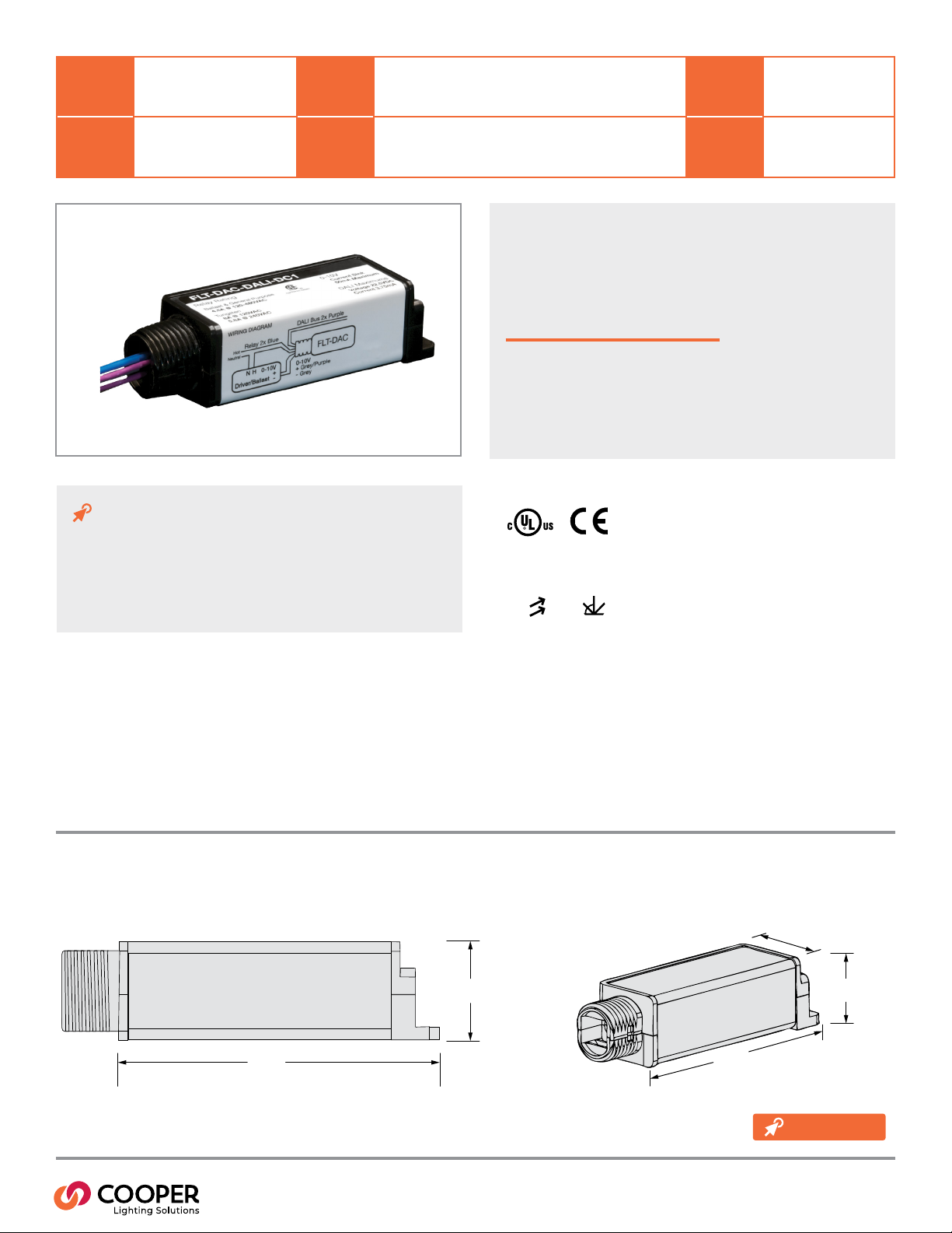
FLT-DAC-DALI-DC1 &
FLT-DAC-DALI-DC2
DAC - Digital to Analog Converter
Typical Applications
Oce • Education • Healthcare • Hospitality • Retail •
Industrial • Manufacturing
Interactive Menu
• Ordering Information page 2
• Additional Resources page 3
• Wiring Diagrams page 4
• Connected Systems page 5
• Product Warranty
Top Product Features
• Built-in latching relay and 0-10V current sinking interface
• All DAC’s device settings congured through the software
• Automatic detection of WaveLinx Wired Local Bus loss of power
for Emergency lighting control (UL924)
• Available for Class 1 or Class 2 wiring congurations
• Ultra-low prole form factor designed
Dimensional Details
Side View
Product Certication
Product Features
WaveLinx Wired
Local Bus
Tuning
Control
Angled View
1.125”
(28.58mm)
3.94”
(100.0mm)
1.0”
(25.4mm)
3.94”
(100.0mm)
1.0”
(25.4mm)
additional
product diagrams
PS503276EN page 1
December 2020
Page 2

WaveLinx Wired
Order Information
Catalog Number
Catalog Number Description
FLT-DAC-DALI-DC1
FLT-DAC-DALI-DC2
Product Specications
Key Features
• Built-in latching relay and 0-10V current sinking interface used to integrate
individual or a group of dimmable 0-10V ballasts/drivers
• All DAC’s device settings (fade, scenes and groups) congured through the
software, eliminating the need for manual adjustments
• Automatic detection of the WaveLinx Wired Local Bus power loss with default to
closed and full bright (100% lighting)
• Available for Class 1 or Class 2 wiring congurations
• Ultra low prole form factor designed to t inside driver/ballast compartment of
most standard luminaires
• Easily mountable to xture housing through standard knockout using supplied 90°
elbow and mounting clip
• Powered by the WaveLinx Wired Local Bus (via SCMD4). Line in and load out
connection to driver/ballast, neutral & ground connection are not required.
Mechanical
Dimensions: 1”H x 3.94”W x 1.125”L (25.4mm x 100mm x 28.6mm)
Mounting:
• In xture or junction box mounting only.
Refer to Wiring Diagram section of spec sheet for proper wiring details.
Enivironment:
• Temperature: 32°F to 140°F (0°C to 60°C)
• Relative Humidity: 10% to 90% (non-condensing). For indoor use only.
Electrical
Relay Output:
•
Input Voltage: 120-480 VAC +/- 10%
•
Maximum Ballast/General Load for operating temperature lower than
104F: 4.5A @ 120-480 VAC
•
Maximum Ballast/General Load for operating temperature higher than
104F: 3A @ 120-480VAC
•
Maximum Tungsten Load: 8A @ 120 VAC, 5.8A @ 240 VAC
•
Input Frequency: 50/60 Hz
Control Specication:
• Communication Interface: WaveLinx Wired Local Bus (topology, polarity free)
•
Current Draw: 3.75mA
•
Analog Dimming Current Draw: 0-10 VDC, 50mA max current sink only
Note: Upon rst power up allow 4-6 seconds before sending commands
Wiring:
•
Relay: 18 AWG solid TFN non-polarized pair
•
0-10V Dimming: 18 AWG solid TFN polarized pair
•
Communication: 18 AWG stranded PTGE plenum rated non-polarized pair
Digital to Analog Converter - wiring exits with line voltage wiring for Class 1 installations of the two wire communications bus.
Digital to Analog Converter - wiring exits with line voltage wiring for Class 2 installations of the two wire communications bus.
Digital to Analog Converter
Standards/Ratings
• cULus Listed - Energy Management Equipment (UL916)
• Manufactured in an ISO 9001 certied factory
• Meets ASHRAE Standard 90.1 requirements
• Meets IECC 2015 requirements
• Meets CEC Title 24 requirements
Warranty
Five year warranty standard
Overview
The Digital to Analog Converter (DAC) is a lighting control device used to control any standard 0-10V current sourcing dimmable ballast/driver.
It allows dimming control by sending 0-10V dimming and on/off commands to the DAC via the WaveLinx Wired Local Bus.
PS503276EN page 2
December 2020
Page 3

WaveLinx Wired
System architecture
Simple WaveLinx Wired system
WaveLinx Wired
Area Controller
Digital to Analog Converter
WaveLinx Wired Local Bus (polarity, topology free)
SCMD4
SCMD4
Complete WaveLinx Wired system
DMX Fixture
DMX Fixture
SCD96
DMX Out
iLumin
CLS - INEO
Touchscreen
Wallstation
Occupancy
Sensor
Dual Tech
occupancy
sensor
Powerpack
0-10V LED
controller
LED Luminaire
with 0-10V driver
LED Luminaire
with DALI driver
WaveLinx Wired
Area Controller
ILS-0020
8 local busses
Curtain
Control
SI-2-D
installed within a panel
AV & Partitoning
WaveLinx Wired Local Bus
wallstation
controller
0-10V LED luminaire
Blind
Control
RI-2
Relay Out
Occupancy/
Daylight Sensor
occupancy/
daylight Sensor
Circuit Breaker Panel
Wallstation
LED luminaire with DALI driver
powerpack0-10V LED
Reverse phase track lighting
ILM-2110
Medium Area Controller
24 Relays, 12 0-10V, 4 local busses
WaveLinx Wired Network (daisy chain wire using Cooper LCCP, LCCNP, or Belden 1502, 1502P)
dual technology
occupancy sensor
LDCM
(0-10V to Reverse
Phase Module)
24 Relays
and 12
0-10V zones
relay pack for
LED or plug load
Circuit Breaker Panel
WaveLinx Wired
Configuration
Software
Building LAN or VLAN
ILL-3301
Large Area Controller
36 Relays, 36 0-10V, EG2 installed
WaveLinx Wired Local Bus
WaveLinx Wired Local Bus
36 Relays
and
0-10V zones
BMS Pro
S1
A1
B1
S0
A0
B0
A6
A5A4A3
A2
A7
B3
B2
Circuit Breaker Panel
TC1
Network timeclock
-PWR
+PWR
FRAME GND
ETHERNET
RS 485
GNDRS 485-
RS 485+
S3
S2
FG
PWR-PWR+
SGA-B+
Building WLAN
Occupancy/
Daylight Sensor
BACnet
Building
Management
System
iLumin
APP
ILS-0020
Small Area Controller
0 Relays, 0-10V, 8 local busses
8 local busses
Wallstation
Relay pack for
LED or plug load
Wallstation
PS503276EN page 3
December 2020
Page 4

WaveLinx Wired
Typical schematic
Digital to Analog Converter
WaveLinx Wired
Area Controller
ILS-0020
Neutral
LINE
WaveLinx Wired
Area Controller
ILS-0020
Wiring Diagram
FLT-DAC-DALI-DC1 & FLT-DAC-DALI-DC2
WaveLinx Wired
Accessory
Wallstation
Neutral
LINE
WaveLinx Wired Accessory
TSI-1-NA
WaveLinx Wired
0-10V LED
Controller
TSI-1-NA
Communicates to up to 25
touchscreens. The TSI-1-NA
and touchscreens must be on
the same physical network and
IP address range.
WaveLinx Wired
Multisensor
Category Cable
PoE Switch
LWP-SW-PoE-8-8
(or by others)
WaveLinx Wired
5.5" Touchscreen
TSE55-B
LED addressable
luminaire
Category Cable
EoPEoP
WaveLinx Wired
8" Touchscreen
TSE80-B
WaveLinx Wired Local Bus
(topology, polarity free)
Relay 2x Blue
Hot
Neutral
DAC-DC1
N H
Driver/Ballast
Relay 2x Blue
Hot
Neutral
0-10V
+
-
0-10V
+ Grey/Purple
– Grey
WaveLinx Wired Local Bus
(topology, polarity free)
DAC-DC2
N H
0-10V
Driver/Ballast
Note: Install in accordance with all applicable National and local electrical and building codes.
Note: Specications subject to change without notice.
+
-
0-10V
+ Grey/Purple
– Grey
PS503276EN page 4
December 2020
Page 5

WaveLinx Wired
Digital to Analog Converter
Sample System Topology:
This diagram shows the main components of the WaveLinx Wireless and Wired Connected Lighting system.
The WaveLinx wireless system communicates using wireless mesh technology based on the IEEE 802.15.4 standard. A PoE LAN
connection for each Wireless Area Controller (WAC) is required for power and data access to the building lighting network.
The WaveLinx wired system controls the devices using relay, 0-10V, DMX and the WaveLinx wired digital local bus. The WaveLinx
wired system connects to the building LAN using the EG2 module. Each WaveLinx wired area controller communicate on the
WaveLinx wired network. The WaveLinx wired network supports over 60,000 devices.
The Trellix Core, WaveLinx Area Controllers (WAC) and WaveLinx Ethernet Gateways (EG2) communicate with each other over the
Ethernet network.
Please refer to the WaveLinx Wireless Network and IT Guidance Technical Guide and WaveLinx Wired Network and IT Guidance
Technical Guide for more information.
IoT
and
API
Touchscreen
Partner Apps
WaveLinx Wired
Local Bus
Smart Lighting Apps3rd Party Integration
Trellix Admin Trellix LightingTrellix Exchange
WaveLinx Wired
Network
WaveLinx
Wired
System
Trellix Core
wired
OR
wireless
WaveLinx
Wireless
System
Firewall
Up to 300
Wireless Area
Controllers
(Trellix Core
Enterprise & Virtual)
WaveLinx Network
Wireless Area
Controller
View
and IT Guidance
Technical Guide
Touchscreen
Smartphone
with
WaveLinx
app
Area or Room
20A
Relay
WaveLinx Wired local bus devices
(up to 64 devices per local bus)
Room Based
Occupancy Sensor
Control Systems
• Trellix
• WaveLinx Wireless
• WaveLinx Wired
• VividTune
Scene
Wallstation
Addressable
Fixture
Relay Controlled
Fixture
Area or Room
(15 + 1 construction area)
347V and 20A
Dimming Relay
Wireless Controlled Lighting ready devices
(up to 150 per WAC)
Room Based
Occupancy Sensor
Controlled
Receptacle
Scene
Wallstation
WaveLinx-Integrated
Ambient
WaveLinx-Integrated
Outdoor
Cooper Lighting Solutions
1121 Highway 74 South
Peachtree City, GA 30269
P: 770-486-4800
www.cooperlighting.com
© 2020 Cooper Lighting Solutions
All Rights Reserved.
Specifications and dimensions
subject to change without notice.
PS503276EN page 5
December 2020
 Loading...