

Page 1

Fail-SafeGermicidal UV Upper Air
Commissioning and
Ongoing Maintenance
Measurement Guidelines
November 30, 2020
Page 2
Before You Begin:
Read and understand this entire guide, the luminaire installation
instructions, and any site-specific documents before attempting to install,
commission or operate these luminaires. Failure to read and follow all
provided instructions may result in damage or injury.
It is the responsibility of the installer to
ensure that persons will not be exposed to
excessive UV radiation during equipment
operation. This will require the installer to
conduct an assessment of irradiance levels
per the instructions listed in this document
in the surrounding occupied spaces prior
to occupancy and to repeat assessment
whenever relamping is completed.
This document applies to following products:
Fail-Safe GAC - Germicidal UV 2x2 Grid Ceiling Mount
Fail-Safe GAW - Germicidal UV Louvered Wall Mount
Page 3
Table of Contents
General Instructions and Materials Required
Step 01: Establish Baseline
Step 02: Eye Level Safety measurements
AA
Step 03: Documentation and Deliverables
Final Notes and Appendices
Germicidal U V Upper Air 1
Page 4
General Instructions and Materials Required
Upper Air Germicidal UV
radiation measurements
must be taken:
• Upon initial installation
• Whenever new lamps are installed
• Whenever modifications are made to the room or
upper air installation conditions
(e.g. height, position, change of walls or ceiling material, room dimension changes, etc.)
• Whenever any reports or complaints of possible
overexposure are received, or is reasonably
expected
Required Materials (sold separately)
Personal protective
equipment (PPE):
• Safety glasses with side panels
• Long sleeve shirt, long pants
and closed toe shoes
• Skin protecting gloves
1
• Sunblock cream
(containing either zinc oxide or
titanium dioxide for head, neck,face
and other areas of exposed skin)
1. National Ins titute for Occupational Safety and Health. Atlanta, GA: National Institu te for Occupational Safety a nd Health; 2009.
Environmental control of tuberculosis: basic upper-room ultraviolet germicidal irradiation guidelines for healthcare settings.
2. ICNIR P (2007) Prote cting Worker s from Ultraviolet Radiation
3. End TB Transmissio n (ETTI) (2019) Maintenance of Upper-Roo m Germicidal Ultraviolet (GUV) Air Disinfection Systems
for TB Transm ission Control, Sto p TB Par tnership, Ge neva, S witzerland. www.stoptb.org/wg/ett /resources.
4. ACGIH. (2 017). TLVs® and B EIs®. Americ an Conferen ce of Governme ntal Industrial Hyg ienists, Ci ncinnati, O H.
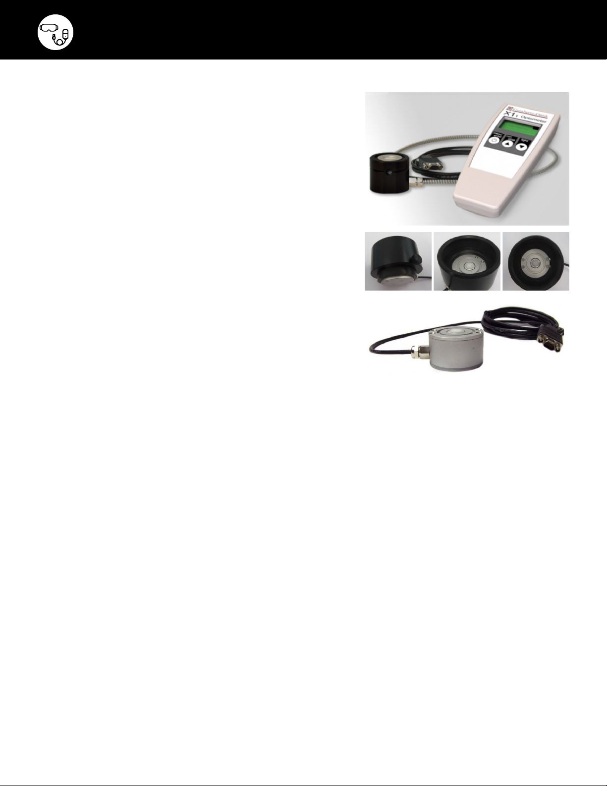
Calibrated X1-5 Optometer
- Gigahertz - Optik
• Step 1: For output range of
1-50 μW/cm², calibrated at first
decimal (0.1 μW/cm²)
• Step 2: For measuring safety level
at 0.2 μW/cm² calibrated to second
decimal (0.01 μW/cm²)
Measuring tape and
documentation materials
Ladder and Tripod
UV-3725-4 Radiometric
Detector. UV-C 254nm
irradiance with cosine
corrected field-of-view.
Gigahertz -Optik
UV- 3718Z-01 Detector
Accy: 80° FOV adapter
for UV-3718 detector
2, 3, 4
2 Fail-Safe
Page 5

Premeasurement Actions
• Prior to the installation, Cooper Lighting Solutions recommends 100hr burn-in of the lamps.
Once the burn-in is complete, the lamps will be stable and considered abaseline for
commissioning measurement.
Failure to complete the 100hr burn-in could result in higher initial readings. The space should
never be occupied by humans or pets prior to completing all measurements.
• Make sure you have the latest site documents including latest architectural and electrical
drawings, simulated calculation report (if performed), list of surface materials and reflectance
values (see Appendix B), site audit notes or previous measurements (if applicable) to compare
with the current situation.
• Check if the usage of the space (occupant tasks, hours occupied, etc) is the same as it was
when the system was designed. If there is a change, register it.
• Look for obstacles (hanging from the ceiling or higher objects from the floor) that may interfere
with the UV-C light, register them.
• Check if there are nearby items (smoke detectors, alarms, projectors, wi-fi routers, etc.) with
materials or paint that can be degraded by UV-C and advise thecustomer.
• Energize luminaires and allow to stabilize for 10 minutes prior to beginning any measurements.
• Thoroughly clean the sensor lens according to sensor manufacturer instructions or with
Isopropyl Alcohol before beginning measurements.
1
• Look for standard luminaires installed in the ceiling directly in the irradiance path that may reect
light into the occupied zone. Cooper Lighting Solutions recommends moving or removing these.
1. ASH RAE GPC 37 (D raft).
Germicidal U V Upper Air 3
Page 6

Step 01: Establish Baseline
Instructions for
Measuring
1. Acquire all necessary PPE.
2. Zero the UV meter according to the meter manufacturer’s
instructions.
3. Remove the cap and position the sensor 3ft (0.91m)
from the center of the upper-room GUV luminaire.
4. Point the sensor probe vertically, aiming in the beam ofthe
luminaire, the center of the sensor should be inthe center
of the UV-C beam.
5. Record the reading in the log book, this is the initial
baseline output to be referenced by all future readings after
replacement lamps are installed.
1
Figure 1
Figure 1: The detector is raised and lowered to find maximum output (irradiance) of
the UV beam for recording output. If allowed, permanent marker on the floor would
facilitate repeat measurement. Or use a yard/meter stick between the face of the
luminaire and the GUV radiometer’s detector.
6. Repeat steps 1-6 at 6ft (1.83m) from the center
of the upper-room GUV luminaire.
7. Compare results to Appendix A: Dosing Recommendations.
If above max permissible UV exposure, disconnect the
device and notify Facilities/Owner.
Note: Upon luminaire relamping and/or cleaning, changes to site
conditions (painting, installation of new luminaire in the irradiance path,
changing or resurfacing reflective surfaces, installation of obstructions in
the irradiance path, etc.) and/or changes to site usage, repeat steps 1-7.
1, 2
1. End TB Transmission (E TTI) (2019) Maintenanc e of Upper-Room Germici dal Ultraviolet (GU V)
AirDisinfection Systems for TB Transmission Co ntrol , Stop TB Partnershi p, Geneva, Switzerland.
www.stoptb.org/wg/ett/resources.
2. Nardel l EA, Bucher SJ, B rickner PW, Wa ng C, Vincen t RL, Becan -McBride K, Jam es MA, Michael M,
Wright JD. Safety of upp er-room ultraviolet germicidal air d isinfection for room occup ants: result s
from the Tuberculosis Ul traviolet S helter Study. Public Health Rep. 20 08;123:52–60 w.
4 Fail-Safe
Page 7

Step 02: Eye Level Safety measurements
Instructions for
Measuring
1. Create a grid of measurements on the floor,
placing the tripod at an equally-spaced distance
(see table to the right).
2. Place the tripod head at the default 6ft (1.83m) or
acceptable eye level for the tasks that take place in
the space.
3. Make sure to use the 80° field of view adapter on the
detector for these measurements.
4. At each grid point, take five measurements.
• For the first measurement, orient the detector
(normal of the detector surface) horizontally
(pointed at ceiling).
• Next, orient the detector vertically, pointing
straight ahead along the typical line of sight
formeasurements in all directions.
5. Record the location of all measured points, clearly
highlight if any measurement is higher than the
maximum agreed upon value for the application
(based on the Maximum Permissible UV-C Exposure
guidelines in Appendix A).
to be taken andsystem should not be energized until
measurements are in alignment with Appendix A
dosage recommendations.
1
Corrective action needs
Measurement Grid
Space
Length
(ft /m)
<6ft/<1.83m 1.5ft/0.5m 4
6 - 2 4 f t/ 2-7. 5 m 3f t/1m 5
24 - 65 f t/ 7.5 - 2 0m 4.5ft/1.5m 10
>65ft/>20m 6ft/1.83m 15
• The larger the area, the bigger the
distance between measurement points.
• Grid should not align with luminaire layout.
• If a simulated calculation of the space has
been provided, the measurement grid may
follow the simulated grid points for correlation.
• Reduce grid distance:
- Where multiple luminaire are combining energy
- Wherever highly reflective surfaces might be found
- At task areas
Maximum
grid spacing
(ft /m)
Minimum
grid points
2
Sensor Orientation
Horizontal
3
1. See A ppendix A.
2. End TB Transmissio n (ETTI) (2019) Maintenance of Upper-Roo m Germicidal Ultraviolet (GUV) Air
Disinfectio n Systems for T B Transmis sion Control, Stop TB Par tnership, G eneva, Switzerland.
www.stoptb.org/wg/ett/resources.
3. See App endix B.
Vertical
Germicidal U V Upper Air 5
Page 8

Step 02: Eye Level Safety measurements
Figure 2
Figure 3
Figure 2: Technician checking eye level safety with GUV radiometer. Searching for
the hot- spots at eye level using a hand-held radiometer and sensor with 80 degree
field -of-view cover to mimic the structure of the brow and eye.
Figure 3: A tape measure is recommended to set the tripod to 6f t (1.83m).
Figure 4: A tripod is recommended for easy repetitive measurements at 6ft (1.83m)
along the grid.
Figure 5: Measuring along the line of eye sight of the occupant.
Figure 4
6 Fail-Safe
Figure 5
Page 9

Step 03: Documentation and Deliverables
1. Mechanical / Electrical Installation report
(reporting if the luminaires were correctly installed,
following mounting instructions and design guidance).
2. Visual / photographic inspection
(confirming if all elements noted during the audit are still valid).
3. Irradiance measurements should be recorded and saved (recorded in
XLS, PPT or Word – not scanned handwritten values).).
4. Baseline Measurements – in the beam (Step 01).
5. Eye Level Safety and compliance - Out of the beam (Step 02)
at 6ft (1.83m) or the height used in the design.
6. All documentation should be made available to all parties involved
(installing/commissioning contractor, distributor, owner)
and saved in a secure location for future reference.
Germicidal U V Upper Air 7
Page 10

AA
Final Notes and Appendices
Dosing Recommendation
Maximum permissible UVC exposure
This international standard adopts the REL1 maximum
permissible UVC exposure values and the maximum
permissible UVC exposure shall not exceed the ACGIH
TLHand NIOSH REL
40hour work week exposure to UV radiation at 254 nm.
1
of 6.0 mJ/cm2 for an 8 hour day,
2, 3
Maximum permissible UVC
exposure for radiation at 254 nm
Permissible UVC
exposure time
24 hours 0.07
18 hours 0.09
12 hours 0.14
10 hours 0.17
8 hours 0.2
4 hours 0.4
2 hours 0.8
1 hour 1.8
30 minutes 3.3
15 minutes 6.7
10 minutes 10
5 minutes 20
1 minutes 100
30 seconds 200
15 seconds 400
5 seconds 1200
1 second 6000
Threshold Limit Value® (TLV®) consideration should be
based on real-time occupancy of spaces treated by UVGI.
This recommendation is supported by recent UV monitoring data
from First and Colleagues
poorly predict actual exposure of room occupants.
1. CDC/ NIOS H. Recommen ded Ex posur e Limit . REL, 2005
2. NIOSH . Criteria for a r ecommended stan dard: Occupational expos ure to ultravio let radiatio n
Publication 73-11009. National Institute for Oc cupational Safety and Health, Was hington, D.C, 1972
3. ACGIH. 2 007. TLVs® and BEIs®. Ame rican Conference of Govern mental Indu strial Hygie nists,
Cincinnati, OH
4. First M.W., Weker R. A., Yasui S., Nardell E .A. Monitoring human exp osures to upper-room
germicidal u ltraviolet i rradiation . J. Occup. Environ. Hyg. 2005, 2 pp. 28 5–292
Effective irradiance
2
µW/cm
<0.8 μW/cm3
operating
range for TLV
assessments
>0.8 μW/cm3
is not allowable
for design
acceptance
criteria and
commissioning
4
, who founded that peak meter readings
3
UVC radiation reectance
Material Refl. (%)
Aluminium:
untreated surface
Aluminium:
treated surface
Aluminium:
sputtered on glass
“ALZAK”
treated aluminium
“DURALUMIN” 16
Stainless steel
/Tin plate
Chromium plating 39
Various white
oil paints
Various white
water paints
Aluminium paint 40-75
Zinc oxide paint 4-5
Black enamel 5
White baked
enamel
White plastering 40-60
Magnesium oxide 55-60
Calcuim carbonate 75-88
Linen 70-80
Bleached wool 17
Bleached cotton 4
Wallpapers: Ivory 30
Wallpapers: white 31
Wallpapers: white 21-31
Wallpapers:
red printed
Wallpapers:
ivory printed
Wallpapers:
brown printed
White notepaper 25
Reed NG, Wengraitis S , Ultraviol et Spectral
Reectanc e of Ceiling Tiles, and Implications for
the Safe U se of Upper- Room Ultraviolet G ermicidal
Irradiation Photochemistry & Photobiology 2012, 88:
1480-14 88
40-60
60-89
75-85
65 -75
25-30
3-10
10-35
5-10
31
26
18
Ceiling tiles reectance values
Incl
ID
specular
A 0.035±0.001 0.034
B 0.043±0.002 0.041
C 0.048±0.001 0.047
D 0.051±0.001 0.05
E 0.052±0.002 0.047
F 0.055±0.006 0.054
G 0.060±0.002 0.059
H 0.064±0.004 0.062
I 0.070±0.001 0.065
J 0.071±0.005 0.071
K 0.071±0.001 0.069
L 0.074±0.001 0.071
M 0.076±0.003 0.067
N 0.096±0.003 0.041
O 0.106±0.006 0.047
P 0.107±0.024 0.05
Q 0.122±0.007 0.047
R 0.151±0.008 0.054
S 0.152±0.009 0.059
T 0.165±0.021 0.062
U 0.237±0.011 0.065
V 0.240±0.033 0.071
W 0.240±0.063 0.069
X 0.244±0.023 0.071
Y 0.245±0.070 0.067
Z 0.260±0.048 0.288
AA 0.260±0.035 0.243
BB 0.273±0.007 0.274
CC 0.275±0.016 0.28
DD 0.276±0.013 0.283
EE 0.276±0.026 0.29
FF 0.282±0.029 0.306
GG 0.334±0.024 0.333
HH 0.353±0.031 0.363
II 0.362±0.028 0.364
JJ 0.423±0.103 0.41
KK 0.459±0.015 0.438
Excl
specular
8 Fail-Safe
Page 11

AA
Final Notes and Appendices
Ceiling tile information
Manufacturer Item Name Item No. Materials Notable surface features ID
Armstrong Armatuff 860 Wet-formed high-density mineral ber Latex paint R
Armstrong Ceramagurad 605 Ceramic and mineral ber composite Scrubbable plastic nish KK
Armstrong Cirrus 574 Wet-formed mineral ber Latex paint HH
Armstrong Cirrus (camel) 589 Wet-formed mineral ber Latex paint S
Armstrong Cirrus (platinum) 589 Wet-formed mineral ber Latex paint X
Armstrong Clean Room Mylar 1721 Wet-formed mineral ber Soil-resistant polyester lm G
Armstrong Clean Room VL 870 Wet-formed mineral ber Vinyl-faced membrane K
Armstrong Cortega 769 Wet-formed mineral ber Latex paint V
Armstrong Crossgate 2625 Wet-formed mineral ber Latex paint AA
Armstrong Dune 1772 Wet-formed mineral ber Latex paint U
Armstrong Endura 639 Wet-formed high-density mineral ber Vinyl latex paint GG
Armstrong Fine Fissured School Zone 1714 Wet-formed mineral ber Latex paint FF
Armstrong Fine Fissured (camel) 1729 Wet-formed mineral ber Latex paint T
Armstrong Fine Fissured (haze) 1729 Wet-formed mineral ber Latex paint DD
Armstrong Fine Fissured (techblack) 1729 Wet-formed mineral ber Latex paint D
Armstrong Fine Fissured (white) 1729 Wet-formed mineral ber Latex paint Z
Armstrong Fine Fissured Open Plan 1754 Wet-formed mineral ber Latex paint II
Armstrong Georgian 17 Wet-formed mineral ber Latex paint CC
Armstrong Graphis 1753 Wet-formed mineral ber Latex paint J
Armstrong Latitudes 8005 Wet-formed mineral ber Latex paint W
Armstrong Ledges 8011 Wet-formed mineral ber Latex paint P
Armstrong Mesa 680 Wet-formed mineral ber Latex paint E
Armstrong Optima 3151
Armstrong Painted Nubby 3101 Fiberglass Latex paint EE
Armstrong Pebble 2989 Fiberglass Latex paint N
Armstrong Random Fissured 2910 Fiberglass Scrubbable vinyl lm facing F
Armstrong Sansera 573 Embossed wet-formed mineral ber Latex paint Y
Armstrong Shasta 2906 Fiberglass Scrubbable vinyl lm facing H
Armstrong Stratus 531 Wet-formed mineral ber Latex paint JJ
Armstrong VL 871 Wet-formed mineral ber Vinyl-faced membrane L
Certain-Teed Ecophon Gedina E — Fiberglass Sound-resistant coating BB
Certain-Teed Fine Fissured High NRC 454 Wet-felted mineral ber Latex paint M
Certain-Teed Symphony F 134,2,4 Fiberglass Laminate C
Certain-Teed Theatre Black F 1910,2 Fiberglass Laminate A
Certain-Teed Vinyl Rock 1140,2- C R F -1 Gypsum Scrubbable vinyl lm facing I
USG Astro Climaplus — Mineral ber — Q
USG Brio Climaplus — Mineral ber — Q
Fiberglass with acoustically
transparent membrane
Acoustically transparent
membrane and latex paint
B
Note: Al l tiles are white unless noted in parentheses next to the model, or in the mo del name itself; ID used to identify specic tiles in Figures, Tables, and tex t.
Germicidal U V Upper Air 9
Page 12

Cooper Lighting Solutions
1121 Highway 74 South
Peachtree City, GA 30269
P: 770-486-4800
www.cooperlighting.com
Canada Sales
5925 McLaughlin Road
Mississauga, Ontario L5R 1B8
P: 905-501-3000
F: 905-501-3172
© 2020 Cooper Lighting Solutions
All Rights Reserved
Publication No. IB519137EN
January 28, 2021 7:54 AM
Cooper Lighting Solutions is a registered
trademark. All trademarks are property
of their respective owners.
Cooper Lighting Solutions est une marque
de commerce déposée. Toutes les autres
marques de commerce sont la propriété
de leur propriétaire respectif.
Cooper Lighting Solutions es una marca
comercial registrada. Todas las marcas
comerciales son propiedad de sus
respectivos propietarios.
Product availability, specifications,
and compliances are subject to
change without notice
La disponibilité du produit, les
spécifications et les conformités
peuvent être modifiées sans préavis
La disponibilidad de productos, las
especificaciones y los cumplimientos
están sujetos a cambio sin previo aviso
 Loading...