

Page 1
EBPLEDC1HV-20W
IB505083EN CLP-049-336 SURE-LITES
INS #
Installation Instructions for the Sure-Lites LED Emergency Driver
WARNING
Risk of Fire/Electric Shock
If not qualified, consult an electrician.
IMPORTANT SAFEGUARDS
WHEN USING ELECTRICAL EQUIPMENT, BASIC SAFETY
PRECAUTIONS SHOULD ALWAYS BE OBSERVED INCLUDING
THE FOLLOWING.
1. READ AND FOLLOW ALL SAFETY
INSTRUCTIONS
2. Do not use outdoor
3. Do not use near gas or electric heaters.
4. Do not use in air handling heated air outlets, sealed and
gasketed fixtures, wet or hazardous location fixtures.
5. Do not let power supply cords touch hot surfaces.
6. Do not use this equipment for other than the intended
use.
7. The use of accessory equipment not recommended
by the manufacturer may cause an unsafe condition.
Servicing should only be performed by qualified service
personnel.
8. Equipment should be mounted in locations and at
heights where it will not readily be subjected to
tampering by unauthorized personnel.
9. Prior to installation, battery connector must be open to
prevent high battery drain on the unit .
10. This product is for use with an emergency LED lighting
load and supplies nominally 20.0 W of power with a
voltage 125 - 200 Vdc in emergency mode for a minimum
of 90 minutes.
11. This product is suitable for use in damp locations where
the ambient temperature is 0°C minimum, +50°C maximum.
Product is also suitable for installation in sealed and
gasketed fi xtures, Product is not suitable for heated air
outlets and wet or hazardous location. Maximum allowable
case temperature is 65°C. See unit label for measurement
location.
12. To avoid electrical shock, please disconnect normal
and emergency power supplies, and battery connector of
the emergency driver before servicing.
Risk of Electric Shock
Disconnect power at fuse or circuit breaker before
installing or servicing.
13. This emergency driver is for factory or fi eld installation
on top of or remote from the fi xture.
14. For Canadian application the output terminals should
be in compliance with the accessibility requirement
of the Canadian electric Code.
15. This device complies with part 15 of the FCC Rules.
Operation is subject to the following two conditions:
(1) this device may not cause harmful interference, and
(2) this device must accept any interference that may
cause undesired operation.
16. This product's chassis must be grounded.
17. Unswitched AC power source of 120 VAC through 277
VAC is required.
18. The battery is sealed, non-maintenance, and is not
replaceable in the fi eld. Please contact manufacturer
for information on service. Do not attempt to service
the battery.
19. Install in accordance with National Electric Code and
local regulatory agency requirements. Installation is to
be performed only by qualifi ed personnel.
20. DO NOT EXCEED TOTAL OUTPUT RATING of source
power equipment.
THIS PRODUCT CONTAINS A RECHARGEABLE
NICKEL-CADMIUM BATTERY.
THE BATTERY MUST BE RECYCLED OR DISPOSED
WARNING
Ni - Cd
OF PROPERLY.
SAVE THESE
INSTRUCTIONS
1
Page 2
Installation Instructions for the Sure-Lites LED Emergency Driver
CAUTION: DO NOT JOIN CONVERTER CONNECTOR UNTIL INSTALLATION IS COMPLETE AND AC POWER IS
SUPPLIED TO THE EMERGENCY DRIVER.
NOTE: Make sure the necessary branch circuit wiring is available. An unswitched source of power is
required. The emergency driver must be fed from the same branch circuit as the AC driver.
This product is suitable for field installation with suitable
LED loads including LED luminaires, DC voltage driven LED
replacements for fluorescent lamps and others. There are 4
checks to determine if your luminaire is eligible for field
installation.
1. Ensure the LED load’s rated power is greater than or equal
to the power output of this emergency LED driver. This is to
ensure that this emergency product will not produce more
power than the LED load can handle, thus ensuring that the
LED load will not be damaged when the system is in the
emergency mode.
2. Verify that the forward voltage of the luminaire’s LED array
is within the limits of this emergency LED driver. The forward
voltage of the LED array is commonly designated as Vf and
should be found on the luminaire markings, in the luminaire
specifications, or imprinted directly on the LED arrays. If
multiple LED arrays are to be driven, verify that the total
forward voltage is within the limits of this product. Using a
voltage meter, it may be possible to directly measure the
voltage across the LED arrays when operating from the AC
driver.
3. Ensure the output current of the LED driver does not exceed
2.0 Amps. This is the current into the blue wire.
4. Ensure there will be sufficient light output in the end
application. Estimate the egress lighting illumination levels
by doing the following:
a. Find the efficacy of the LED load. This can be given
by the luminaire manufacturer. This number will be
given in lumens per watt (lm/w). It is the installer’s
responsibility to validate the luminaire manufacturer’s
efficacy data. This can be accomplished by direct
measurement, by review of independent 3rd party
test data (UL, ETL, etc.), accessing a public database
of 3rd party data (such as Design Lights Consortium,
www.designlights.org), or other comparable means.
b. Lumens can be calculated by multiplying the output
power of the emergency LED driver by the efficacy of
the LED load. In many cases the actual lumen output
in emergency mode will be greater than this calculation
gives, however it will provide a good estimate for
beginning the lighting design of the system.
c. Using the results of this calculation and industry
standard lighting design tools, calculate the anticipated
illumination levels in the path of egress.
Lumens In Emergency Mode = Lumens per Watt of
Fixture * Output Power of Chosen Product
INSTALLING THE EMERGENCY DRIVER
1. Disconnect AC power from the LED luminaire.
2. Mount the emergency LED driver by the mounting tabs using the supplied screws. The luminaire’s installation instructions may provide guidance on the recommended mounting
location.
> Mounting Height: This product meets or exceeds the NFPA
minimum light requirements with all loads, down to the
smallest rated lamp load, at heights up to 7.17ft (2.2m).
Many factors infl uence emergency illumination levels, such
as the lamp load selected, luminare design, and environmental factors therefore end use verifi cation is necessary. For fi eld installations, when the attached luminaire is
mounted at heights greater than 7.17ft (2.2m), the level of
illumination must be measured in the end application to
ensure the requirements of NFPA 101 and local codes are
satisfi ed.
> Remote Mounting: The emergency driver may be remote
mounted from the luminaire. If used in conjunction with
an AC driver, this distance is up to half the distance the AC
driver manufacturer recommends remote mounting the
AC driver from the LED Load. If used without an AC driver,
consult factory. The test button indicator light may also be
remote mounted. CAUTION: Remote mounting can result in
reduced power output. For remote mounting more than fi ve
feet from the luminaire, please consult factory to determine
the minimum necessary wire gauge.
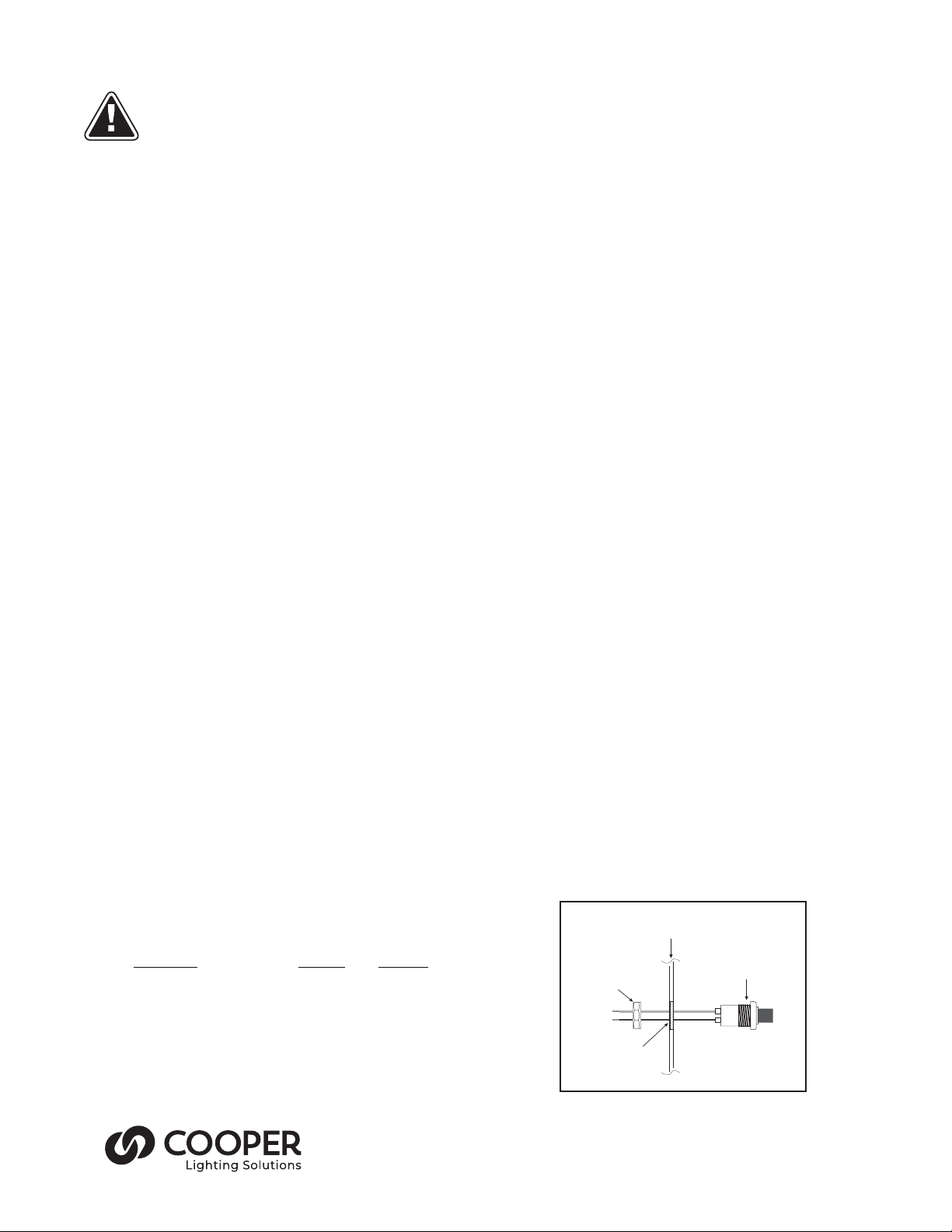
3. Mount the supplied test button indicator light in a location
that is visible and accessible by maintenance personnel. The
test button indicator light mounts through a 1/2” hole which
may need to be made in the luminaire or could come prepunched by the luminaire supplier.
4. Wire the test switch per wiring diagrams provided on these
instructions.
5. If wired correctly, the test button indicator light should
be ON when AC power is supplied to the fi xture, and the
convertor connector is closed indicating that the emergency
driver battery is charging. After installing, mark with the
"PUSH TO TEST" and "CHARGING INDICATOR LIGHT" labels.
Fixture or
Test/Monitor Plate
(Lumens)_ = __________(lm/W)_* __20 (W)
NOTE: This product has been designed to reliably interface
with a wide selection of LED loads and is electrically
compatible with every simple LED array that meets criteria
1 and 2 above. However, compatibility cannot be guaranteed
with all current and future LED systems. Compatibility
testing of the end-use system is suggested. Please contact
the factory with any questions.
Test Button
Hex Nut
Drill or Punch
a 1/2” Hole
2
Indicator Light
Violet
Brown
Page 3

Installation Instructions for the Sure-Lites LED Emergency Driver
6. Select the appropriate wiring diagram to connect the emergency driver to the AC driver and LED load. Make sure all connections are in accordance with the National Electrical Code
and any local regulations.
7. After installation is complete, supply AC power to the emergency driver and join the unit engage connector.
> At this point, power should be connected to both the AC driver
and the emergency driver, and the test button indicator light
should illuminate indicating the battery is charging.
> A short-term discharge test may be conducted after the emer-
gency driver has been charged for one hour. Charge for 24
hours before conducting a long-term discharge test. Refer to
OPERATION.
8. In a readily visible location, attach the label "CAUTION - This
Unit Has More Than One Power Connection Point. To Reduce
The Risk Of Electric Shock, Disconnect Both The Branch
Circuit-Breakers Or Fuses And Emergency Power Supplies
Before Servicing."
NOTE: After installation, it will be necessary to measure
the egress lighting illumination levels to ensure it complies
with national, state, and local code requirements.
OPERATION
During normal operation AC power is applied, the
test button indicator light is illuminated, indicating
that the battery is being charged. When power fails,
the emergency LED driver automatically switches to
emergency power (internal battery), operating the LED
load for a minimum of 90 minutes. When AC power is
restored, the emergency driver returns to the charging
mode.
MAINTENANCE
Although no routine maintenance is required to keep the
emergency driver functional, it should be checked periodically
to ensure that it is working. The following schedule is
recommended:
1. Visually inspect the test button indicator light
monthly. It should be illuminated.
2. Test the emergency operation of the fixture at 30-day
intervals for a minimum of 30 seconds. The LED load
should operate at reduced illumination.
3. Conduct a 90-minute discharge test once a year. The
LED load should operate at reduced illumination for
at least 90 minutes.
! REFER ANY SERVICING INDICATED BY THESE
CHECKS TO QUALIFIED PERSONNEL !
WIRING DIAGRAM
WHITE
WHITE
WHT/RED
BLACK
VIOLET (+)
BROWN (-)
WHITE
WHT/BLK
BLUE
YEL/BLK
YELLOW
Emergency
LED
Driver
TEST BUTTON
INDICATOR
LIGHT
HOT
COMMON
CONVERTER
CONNECTOR
VIOLET
BROWN
WALLSWITCH
AC DRIVER (-)
AC DRIVER (+)
EMERGENCY DRIVER AND AC DRIVER MUST BE FED FROM THE SAME BRANCH CIRCUIT.
TYPICAL SCHEMATICS ONLY. MAY BE USED WITH OTHER DRIVERS.
CONSULT THE FACTORY FOR OTHER WIRING DIAGRAMS.
NOTE: The converter connector must be connected for the AC driver to operate normally.
Cooper Lighting Solutions
1121 Highway 74 South
Peachtree City, GA 30269
P: 770-486-4800
www.cooperlighting.com
© 2020 Cooper Lighting Solutions
All Rights Reserved
Tous droits réservés
Todos los derechos reservados
Printed in USA
Imprimé aux États-Unis
Impreso en los EE. UU.
Publication No.
08/10/20
IB505083EN
20 44229193041
Cooper Lighting Solutions is a
registered trademark.
All trademarks are property
of their respective owners.
Cooper Lighting Solutions est une
marque de commerce déposée. Toutes
les autres marques de commerce
sont la propriété de leur propriétaire
respectif.
Cooper Lighting Solutions es una
marca comercial registrada. Todas las
marcas comerciales son propiedad de
sus respectivos propietarios.
LED (+)
LED (-)
BLACK
WHITE
Product availability, specifications,
and compliances are subject to
change without notice.
La disponibilité du produit, les
spécifications et les conformités
peuvent être modifiées sans préavis.
La disponibilidad de productos, las
especificaciones y los cumplimientos
están sujetos a cambio sin previo aviso.
LED LOAD
AC DRIVER
3
 Loading...