

Page 1
Project Catalog # Type
Prepared by Notes Date
Dene 2
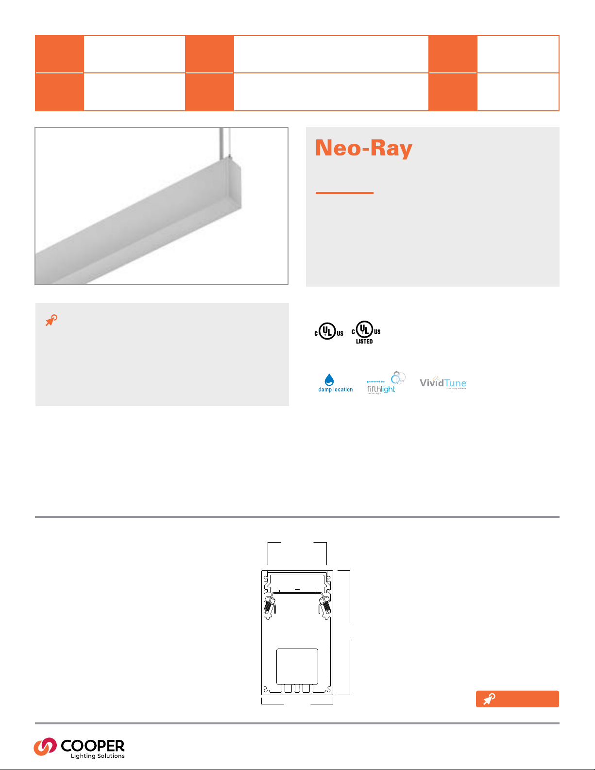
2″ LED
Suspended Pendant
Indirect
Typical Applications
Oce • Education • Healthcare • Hospitality • Retail
Interactive Menu
Product Certication
• Order Information page 2
• Product Specication page 3
• Photometric Data page 4
Product Features
• Performance Data page 5
• VividTune page 6
Top Product Features
• Suspended Slot family in 2″, 3″, 4″ and 5″ housing sizes
• Speciable to the nearest foot
• Multiple lensing options
• Multiple lumen packages
• 0-10V dimming standard; DALI dimming available
• 2700K, 3000K, 3500K, 4000K, and 5000K correlated color temperatures available
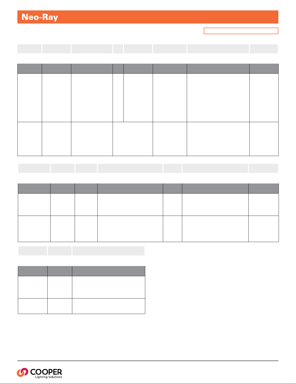
Dimensional and Mounting Details
1.66"
[42mm]
2.02"
[51mm]
3.50"
[89mm]
additional
product diagrams
TD524010EN page 1
March 15, 2021 10:10 AM
Page 2
2″ LED Suspended Pendant Indirect
Order Information
Icon Key: øConsult factory for availability
SAMPLE ORDER NUMBER: S122IP-C330U835-C4JB4F0-1T-UDD-1-W-SWPD1
Series
Series Light Engine Lumen Package UP (Lms/ft) CRI LED CCT Suspension Type Ceiling Type
S122IP=Dene 2
Indirect Pendant
Notes Notes Notes Notes
Light Engine Lumen Package UP
-C=Core
-H=High Performance
-V=VividTune
See performance table for
add’l details. Light engine
must be consistent across
run length. “V” and “H”
light engines not available
in 2ft xture.
V option requires lumen
package of 725 lms/ft or
greater and xture length
of 3 ft+.
ø
(Lms/ft)
330U=330 Lms/ft (2.2W/ft)
530U=530 Lms/ft (3.6W/ft)
725U=725 Lms/ft (5.0W/ft)
925U=925 Lms/ft (6.6W/ft)
1080U=1080 Lms/ft (7.9W/ft)
____U=Custom Lms/ft
Nominal at 3500K/80CRI with no lens.
Please refer to scaling data for other
variables. For custom lumen output,
please refer to additional information
on page 3. VividTune option requires
output >724 lms/ft. 330 Lms/ft and
530 Lms/ft not available on 2ft xture
length. 1080 Lms/ft not valid with DALI
or Lutron Drivers.
CRI LED CCT Suspension Type Ceiling Type Mounting HW
8=80
27=2700K
9=90
30=3000K
35=3500K
40=4000K
ø
50=5000K
2765=2700K-6500K
3050=3000K-5000K
-C4=4ft Aircraft Cable
-C10=10ft Aircraft Cable
-C20=20ft Aircraft Cable
-S4=4ft Stem Mount
-S8=8ft Stem Mount
JB=Gypsum Board, Junction Box, Structure
T1=15/16″ T-Grid (ETG)
T9=9/16″ T-Grid (FTG)
TS=9/16″ Slot (STG), Tegular (FTT), Interlude (ITG)
Notes Notes Notes
Additional lead-time and cost may
apply for 927, 930, 935 and 940
congurations. 2765/3050 VividTune
congurations require V light engine
and W2A driver.
Color
Mounting HW
Color
(blank)=White
B=Black
White mounting hardware
standard
Luminaire Length
(Ft)
Luminaire Length (Ft)
___F0=Nominal Length (blank)=12ft (std)
Max section
length
Max section
length
/8=8ft
Circuiting Additional Section Wiring Voltage Driver Type Shielding Up
Circuiting Additional Section Wiring Voltage
1=Single Circuit
S=Secondary
Circuit
E=Emergency Circuit
B3=Iota Slimline 5W, 120V-277V Integral (ILB-SL-CP5)
T=UL924 EPC Emergency Bypass Relay
U=Universal
(120V-277V)
1=120V
2=277V
3=347V
DD=Standard 0-10V Dimming (1%-100%)
5L=Fifth Light DALI (5%-100%)
L5=Lutron 5 Series (LDE5-Series) 5%-100% EcoSys
LH=Lutron HiLume (LDE1 series) 1%-100% EcoSys
W2A=White Tuning, 0-10V Dimming (VividTune only)
Driver Type
Notes Notes Notes Notes Notes Notes Notes
Minimum xture length is
3ft. Specify to nearest foot
in length.
Individual xtures
congured as 12ft
max by default.
Continuous runs congured as 8ft max
(12ft not available).
Secondary circuit
similar to A/B
switching. Price
adder applies for
“S” conguration.
Battery available on xture ≥ 4ft in length. B3 and T options
not compatible with 347V. Standard battery 4ft battery section
located in the beginning of the xture, but can be relocated
using the linear product congurator. Battery test switch located
in knockout on top of xture.
347V only
available with
DD and
5L driver
options.
DD driver is standard. For non-dimming applications, the driver
will default to full brightness if no connection is made to the
capped dimming wires in the eld.
Options Finish Integrated Sensor
Options
R=GLR Fuse (Fast)
F=GMF Fuse (Slow)
Finish
W=White
S=Silver
B=Black
C=Custom Match
R=RAL Custom
-WAA=WaveLinx Pro Wireless
-WAB=WaveLinx Lite Wireless
-LWIPD1=Enlighted Wireless
-SVPD1=Standalone
(Blank)=None
Integrated Sensor
ø
Notes Notes Notes
Additional lead-time may
apply. Not available with
347V option.
Contact factory for C
and R options. W/S/B
are standard.
DD driver must be selected. Please refer to page 5 for additional detail
required to specify integrated sensors. Integral option not available with
regressed or drop lensing.
Shielding Up
(blank)=No Lens (std)
1=Satin White Diffuser
No lens up standard, use
satin white diffuser when
dust cover desired of top
of the xture is viewable
during normal use.
TD524010EN page 2
March 15, 2021 10:10 AM
Page 3

Product Specications
Construction
• Precision cut housing extruded from 6063 aluminum
• Precision cut & welded end-caps ensure a robust and
clean construction
• Nominal 3′ -12′ illuminated sections used in individual
xtures and 3′-8′ illuminated sections used in
continuous runs
Finish
• Electrostatically applied polyester powder coat paint
LED Module
• Modular LED tray assembly comprising reector and
light engine with quick disconnect wire-harness for
ease of installation and maintenance over the life of
the luminaire
Light Engine
• Offered with two next generation Neo-Ray light
engines delivering industry leading ecacy and
long-life
• LED’s are available in 2700K, 3000K, 3500K, 4000K
or 5000K
• CRI options of either ≥80CRI or ≥90CRI (Lumen
output will be affected - please refer to the lumen
adjustment factor table)
LED Drivers
• LED system coupled with electrical driver
• Traditional electronic drivers are available for 120-
277V and 347V applications
Controls and Integrated Sensors
• Equipped standard with a 0-10V continuous dimming
driver. Compatible with most standard dimming
devices
• Additional control types are available (DALI & Lutron)
at an additional cost
• WaveLinx and Enlighted wireless sensors as well as
stand-alone sensors available
Mounting
• Suspended
2″ LED Suspended Pendant Indirect
Lengths
• Available in any length (2ft min) with a resolution of
1 foot. Max section length of 12ft (8ft max used on
continuous runs and available for individual xtures)
• Additional xture lengths are available please consult
factory. All lengths are nominal and do not include
end caps.
Corners and Transition Pieces
• Corners and other transition pieces are fully luminous
• Constructed using precision mitered housing and
lens components
• Extrusions are welded to ensure a precise and robust
assembly
• Standard 90° horizontal corners as well as custom
corners are available
• Consult online linear congurator or the factory for
precise corner locations and for ordering
• Alternative transition pieces such as T’s, Y’s, X’s, etc.
are also available Ø
Indirect Snap-In lensing Options
• Satin Flush - Flush, high diffusion glare-free lens
• No Lens - No lens option provides the lowest cost
solution with the highest ecacy
Reflectors
• Precision formed cold-rolled steel reectors with high
reectivity
Lumen Maintenance
• 90% (L90) of initial light output at 61,000+ hrs
• 70% (L70) of initial light output at 237,000+ hrs
• Derived from TM-21 standard @25°C for worst case
operating conditions
Custom Lumen Output
• Custom lumen output expressed option in Lumens
per foot (e.g. -725D for 725 Lms/ft down). Refer to
additional detail on page 4.
Electrical
• Dimming provided as standard
• Dimming wires capped with wire-nuts for non-
dimming applications
• Optional battery backup options provided
• Default battery location is internal to xture
• Default emergency section is 4ft in length and
located at the beginning of the xture unless
designated elsewhere
• Estimated lumen output = battery wattage * min
ecacy (see performance table)
• The EPC option will bypass local controls and
dimming upon loss of normal power. This option is
required when the xture has both integrated sensors
and emergency circuiting
Integrated Sensors
• Please reference page 5 for details
Weight
• 2.6 lbs per foot
Approvals
• cULus - listed for damp locations
• Meets NYC requirements
• Meets CCEC requirements
• Tested to IESNA LM-79 and LM-80
• Can be used for State of California Title 24 high
ecacy luminaire
Warranty
• Five year warranty standard.
TD524010EN page 3
March 15, 2021 10:10 AM
Page 4

2″ LED Suspended Pendant Indirect
Photometric Data
1,823
1,367
912
456
0.0
0-deg 90-deg
180°
170°
160°
150°
140°
130°
50°
40°
30°
20°
10°
0°
FILE NAME:
S122IP-S675U835-4F0-1E-UDD
22CZ2-24-UNVL830-CD1-U
LUMENS: 5830 Lms
Electronic Driver
LPW: 127 LPW
120°
Linear LED 5000K
110°
100°
90°
80°
70°
60°
3500K
CCT:
Spacing criterion: (II) 1.23 x mounting
WATTS: 45.9 W
height, (⊥) 1.23 x mounting height
TEST NUMBER: P331348
Lumens: 11493
Input Watts: 87.7W
Ecacy: 131.1 LPW
Test Report: 22CZ2-24-UNVL830-
CD1-U.IES
Photometric Overview and Performance Data
Indirect Performance Per Linear Foot at 3500K/80CRI
Nominal
Output
lms/ft W/ft lm/W W/ft lm/W W/ft lm/W
330 2.2 151 2.5 157 2.6 150
530 3.6 151 3.9 163 4.3 148
725 5.0 148 5.3 164 5.9 145
925 6.6 144 7. 1 155 7. 8 141
1080 7. 9 141 8.5 152 9.4 137
Standard High Performance VividTune
View IES les
LUMEN ADJUSTMENT CALCULATIONS
Example 1 - Adjusted Lumen Output Example 1 - Adjusted Lumen Output
Nominal Lumen Output selected = 1025 lms/ft (based on standard of 3500K/80CRI)Nominal Lumen Output selected = 1025 lms/ft (based on standard of 3500K/80CRI)
Lumen Adjustment Factor = 0.801 (2700K/90CRI desired)Lumen Adjustment Factor = 0.801 (2700K/90CRI desired)
Adjusted Lumen Output = Nominal Lumen Output x Lumen Adjustment FactorAdjusted Lumen Output = Nominal Lumen Output x Lumen Adjustment Factor
Adjusted Lumen Output = 1025 lms/ft x 0.801 = 821 lms/ftAdjusted Lumen Output = 1025 lms/ft x 0.801 = 821 lms/ft
Example 2 - Custom Lumen Output based on Required Lumens Per FootExample 2 - Custom Lumen Output based on Required Lumens Per Foot
Total light output (4ft) requirement of 2800 lms, desired CCT and CRI of 4000K/80CRITotal light output (4ft) requirement of 2800 lms, desired CCT and CRI of 4000K/80CRI
Total required lumens per foot @ 4000K= 2800 lms / 4 ft = 700 lms/ftTotal required lumens per foot @ 4000K= 2800 lms / 4 ft = 700 lms/ft
Lumen Adjustment Factor = 1.018 (Requirement based on 4000K / 80CRI)Lumen Adjustment Factor = 1.018 (Requirement based on 4000K / 80CRI)
Total required lumens per foot @ 3500K / 80CRI = 700 lms/ft ÷ 1.018 = 688 lms/ftTotal required lumens per foot @ 3500K / 80CRI = 700 lms/ft ÷ 1.018 = 688 lms/ft
Estimated ecacy = 121 LPW (nd nearest value using table above)Estimated ecacy = 121 LPW (nd nearest value using table above)
Estimated power consumption = 688 lms/ft ÷ 121 lm/W = 5.69 W/ftEstimated power consumption = 688 lms/ft ÷ 121 lm/W = 5.69 W/ft
Custom Lumen Output
Total Light Output Range (lms/ft)
Lumen Adj Factors Indirect Output Range
CCT
80CRI 90CRI 80CRI 90CRI
2700K N/A 0.792 N/A 261-855
3000K 0.943 0.815 311-1018 269-880
3500K 1.000 0.861 330-1080 284-930
4000K 1.010 0.892 333-1091 294-963
5000K 1.010 0.892 333-1091 294-963
If your requirement is expressed in power consumption (W/ft) rather than light output, you If your requirement is expressed in power consumption (W/ft) rather than light output, you
can use the power to lumen output curves to convert power consumption to light output can use the power to lumen output curves to convert power consumption to light output
for specication. Ecacy for cufor specication. Ecacy for custom lumen outputs stom lumen outputs can be estimated using lumen output can be estimated using lumen output
curves or with the use of our online custom lumen output tool.curves or with the use of our online custom lumen output tool.
TD524010EN page 4
March 15, 2021 10:10 AM
Page 5

2″ LED Suspended Pendant Indirect
Corner Transitions
25.000"
[635mm]
25.000”
[635mm]
Integrated Sensor Details and Placement
Sensor Type Wireless Sensor Integration Sensor Mounting Ordering Code
WaveLinx Pro Ye s Integral to Fixture Mounted in solid cover WAA
WaveLinx Lite Ye s Integral to Fixture Mounted in solid cover WAB
Enlighted Ye s Integral to Fixture Mounted in illuminated lens LWIPD1
Stand-Alone
SVPD1
Standard Sensor with Luminaire ControlStandard Sensor with Luminaire Control
Auxiliary Sensor used for Sensor Coverage Auxiliary Sensor used for Sensor Coverage
(wireless systems only)(wireless systems only)
No Integral to Fixture Mounted in solid cover SVPD1
Optional standalone and wireless connected integrated Optional standalone and wireless connected integrated
sensors require use of the DD (0-10V) driver. WaveLinx and sensors require use of the DD (0-10V) driver. WaveLinx and
Enlighted sensors require additional system hardware (not Enlighted sensors require additional system hardware (not
provided) for full functionality. provided) for full functionality.
Standard sensor layout is shown below. Please refer to sensor Standard sensor layout is shown below. Please refer to sensor
coverage pattern diagrams to ensure proper coverage for coverage pattern diagrams to ensure proper coverage for
the application. Standard congurations are available in both the application. Standard congurations are available in both
individual xtures and in continuous runs. Default spacing individual xtures and in continuous runs. Default spacing
is based on the maximum xture length of 12ft and can be is based on the maximum xture length of 12ft and can be
changed to 8ft sensor spacing for additional coverage by changed to 8ft sensor spacing for additional coverage by
selecting the 8ft max xture length option when ordering.selecting the 8ft max xture length option when ordering.
For additional information integrated sensors and connected For additional information integrated sensors and connected
lighting, please visit lighting, please visit Cooper Lighting Solutions’s Connected
Lighting Website
..
INTEGRAL SENSOR
≤8ft Individual
>8ft Individual
Note: When 8ft max section length is used on individual xtures > 8ft, Note: When 8ft max section length is used on individual xtures > 8ft,
sensor placement follows logic for continuous run.sensor placement follows logic for continuous run.
Beginning of
Run (BOR)
Intermediate
Section (INT)
End of Run
(EOR) > 4ft
End of Run
(EOR) ≤ 4ft
TD524010EN page 5
March 15, 2021 10:10 AM
Page 6

2″ LED Suspended Pendant Indirect
Define 2 Pendant LED with VividTune Tunable White
VividTune tunable white luminaires deliver high-quality light in a broad range
of continuously variable color temperatures and intensities. Create a dynamic
environment by adjusting the ambient light warmer or cooler to influence mood,
support the task at hand, or create a dramatic ambience. The ability to control
correlated color temperature and intensity separately using simple controls is the
next evolution of LED lighting for the commercial, educational, healthcare and
hospitality space. The unparalleled flexibility and number of available lighting
environments enable users to find the right light with tunable white.
Performance Data*
Tunable White - Lumen Adjustment Factors
CCT
2700K - - 0.868 0.741
3000K 0.894 0.736 0.893 0.771
3500K 0.946 0.804 0.924 0.809
4000K 0.993 0.868 0.944 0.835
4500K 1.002 0.883 0.961 0.857
5000K 1.002 0.883 0.974 0.874
6500K - - 0.988 0.897
3000K-5000K 270 0K-6500K
80 CRI 90 CRI 80 CRI 90 CRI
CCT
Setting
3000K - 3308 2723
3500K 3700 3500 2975
4000K - 3674 3212
4500K - 3707 3267
5000K - 3707 3267
Standard Catalog # VividTune 80 CRI Catalog # VividTune 90 CRI Catalog #
S122IP-C925U835-X-UDD-W S122IP-V925U83050-X-UW2A-W S122IP-V925U93050-X-UW2A-W
Controlling VividTune Tunable White
VividTune luminaires make tunable white more accessible by using simple and
familiar controls. From wall dimmers to wireless controls, VividTune tunable white
luminaires are compatible with industry standard 0-10V dimming controls. A single
0-10V dimming input is used to control intensity (brightness) while a second 0-10V
dimming input is used to adjust CCT. For suggested control configurations,
go to www.cooperlightingsolutions.com for tunable white application guides.
warm 2700K cool 6500K
warm 3000K cool 5000K
10% 100 %
Intensity
0-10V
CCT
0-10V
CCT
0-10V
Example of Approximate Lumen Calculation
Example of Lumen
Adjustment Calculation
S122IP-V925U83050-X-UW2A-W
at 80 CRI tuned to 3500K
Adjusted Lumen =
published lm x adjusted lm factor
Adjusted Lumen = 3700 x 0.946
Adjusted Lumen = 3500 lm
* Lumen adjustment factors are for reference
and may be different for each product selected.
Refer to IES files for actual performance data on each.
Cooper Lighting Solutions
18001 East Colfax Avenue
Aurora, CO 80011
P: 303-393-1522
www.eaton.com/lighting
© 2019 Cooper Lighting Solutions
All Rights Reserved.
Specifications and dimensions
subject to change without notice.
TD524010EN page 6
March 15, 2021 10:10 AM
 Loading...