

Page 1
CATWALK
2
1
E
F
2
1
E
F
D
C
B
7
6
5
4
3
2
1
E
F
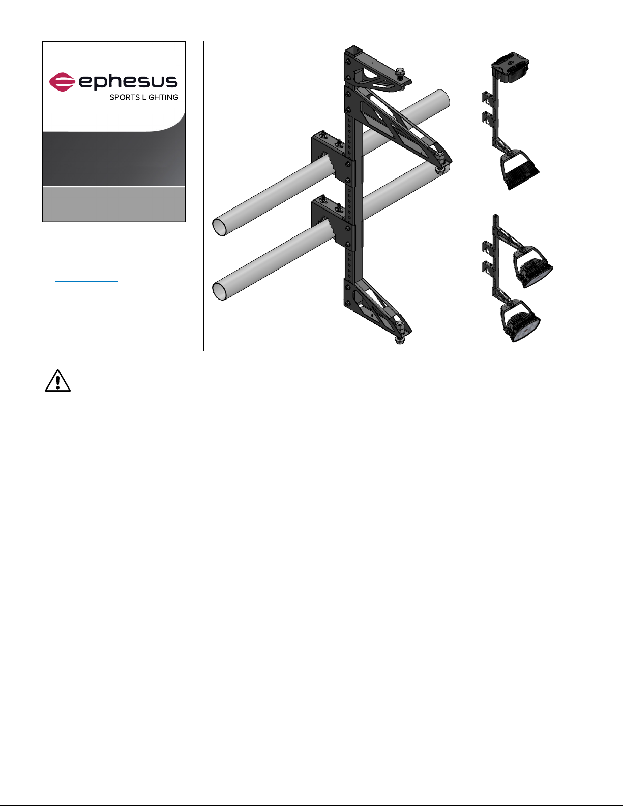
BRACKET
Installation Manual
COMPATIBLE LUMINAIRES:
› LUMASPORT 8
› LUMADAPT 8
› PRISM RGBA
Before You Begin
Read and understand this entire manual and any additional site-specific installation documents before attempting
to assemble, install, or operate the Catwalk Bracket. If you have any questions regarding the product or installation,
contact Cooper Lighting Customer Service at 1-800-573-3600.
Safety
Follow all safety items outlined here as well as any local safety procedures.
1. Verify the structural capacity and safety of all facility/venue supports and mounting apparatus before
installation. See Catwalk Bracket specification sheet for weight and wind loading data.
2. In harsh settings where the system is subjected to factors such as extreme temperatures, high corrosion,
hurricanes, or lightning, always follow local codes and additional protocols to ensure the system components
can withstand the environmental stress for the life of the system.
3. DO NOT make or alter any open holes in the Catwalk Bracket. Do not modify the Catwalk Bracket or luminaire
mounting features. Modifying the luminaire or bracket will void the warranty.
4. Use Personal Protective Equipment including hardhats, safety glasses, reflective vests, electrical safety gloves,
fall protection equipment, and safety toe boots during installation, operation, and maintenance of luminaire.
5. Verify compliance with local standards to prevent access to the area below where installation activities are
occurring to prevent injury from accidental drops of luminaires, tools or hardware.
1
Page 2
A
B
REVISIONS
ZONE
REV.
DESCRIPTION
DATE
APPROVED
D
6
5
4
3
2
1
E
F
2
1X
5
4X
11
3
10X
9
10X
4
1
2X
ASSEMBLY SHOWN FOR EEL-BT-0100-P-2-U-B
T1
TYP.
6
3X
12
6X
7
3X
8
6X
10
4X
13
2X
D
C
B
7
6
5
4
3
2
1
E
F
Risk of Cuts or other Casualty Hazards - Installation and maintenance of this product must be performed
by a qualified electrician. This product must be installed in accordance with the applicable installation code
by a person familiar with the construction and operation of the product and hazards involved.
Risk of Burn - Disconnect power and allow luminaire to cool before handling or servicing.
Risk of Personal Injury - Luminaire may become damaged and/or unstable if not installed properly.
DISCLAIMER OF LIABILITY: Cooper Lighting Solutions assumes no liability for damages or losses of any kind that may
arise from the improper, careless, or negligent installation, handling or use of this product.
ATTENTION Receiving Department: Note the actual Catwalk Bracket description of any shortage or noticeable damage
on delivery receipt. File claim for common carrier (LTL) directly with carrier. Claims for concealed damage must be filed
within 15 days of delivery. All damaged material; complete with original packing must be retained.
APPLICATIONS: The Catwalk Bracket should not be used in area of limited ventilation or inside high ambient temperature
enclosures. It must be stored in a dry location before installation. Do not expose Catwalk Bracket to rain, dust or other
environmental conditions prior to installation. Best results will be obtained if installed and maintained according to the
following recommendations.
Mounting Accessories
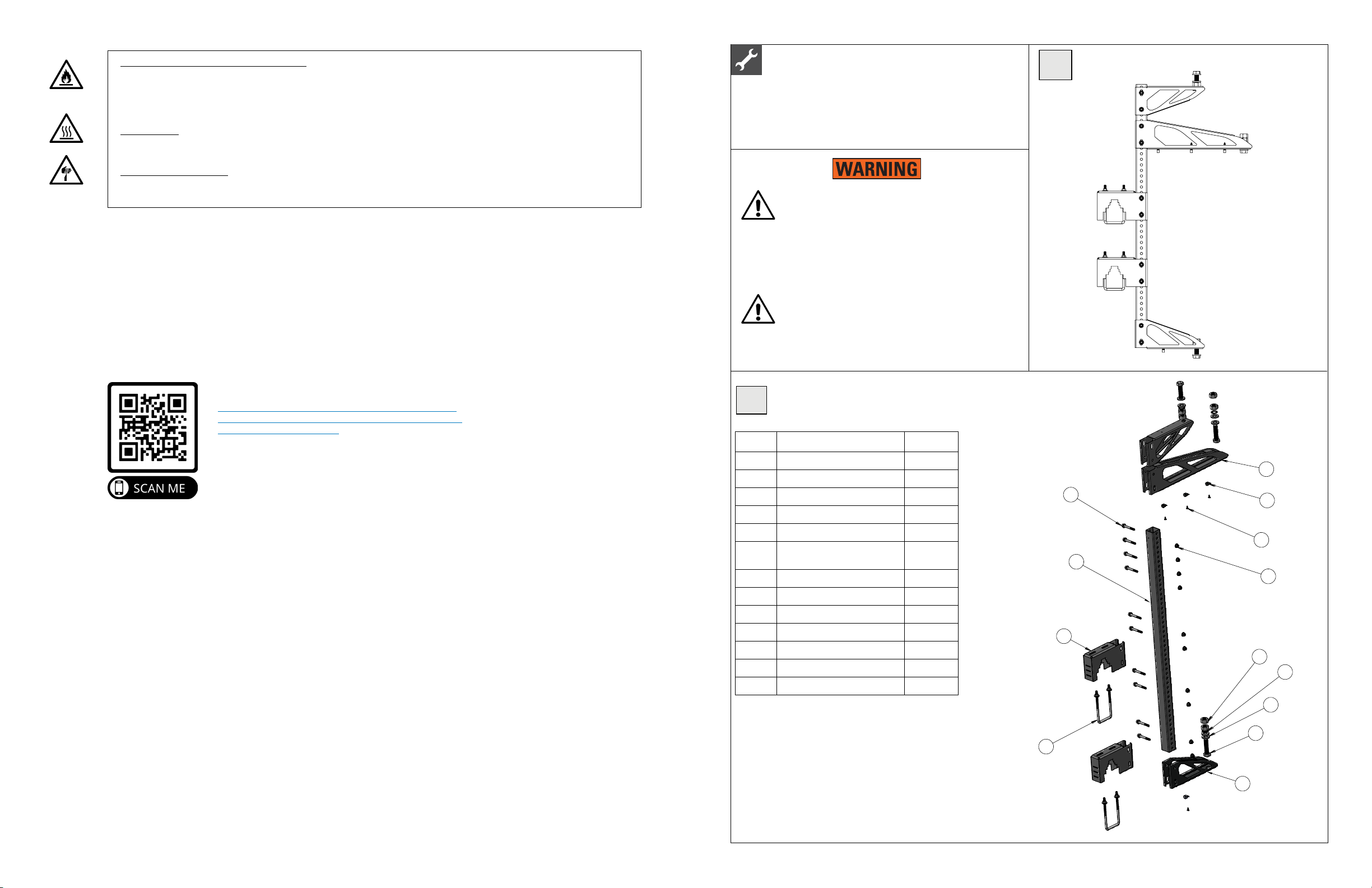
CW1
Catwalk Bracket
Catwalk Bracket
Catwalk bracket is intended to be used for mounting
luminaires to two square or round indoor railings roughly
12in-22in apart luminaires or mounting applications.
Catwalk Bracket may ONLY be installed in the
following physical orientations. Not to be used in
exterior locations or natatorium applications. If this
is required, please contact Ephesus for additional
mounting options. Failure to install the Catwalk
Bracket in approved orientation or location may
result in damage, injury, or death. (Reference
diagram CW4a and CW4b)
Prevent access to area under Catwalk Bracket until
the final torquing is complete.
https://www.cooperlighting.com/content/dam/cooperlighting/brands/ephesus/spec-sheets/ephesus-catwalkbracket-data-specsheet.pdf
Failure to confirm proper configuration may result in injury
or luminaire damage.
CATWALK BRACKET SPECIFICATION SHEET URL:
Catwalk Bracket Parts Diagram¹
CW2
Item # Description Quantity
1 VERTICAL SUPPORT 1
2 TOP CATWALK ARM 1
3 BOTTOM CATWALK ARM 2
4 UNIVERSAL RAILING MOUNT 2
5 CABLE HOLDER 4
6 HEX BOLT, 3/4-10 X 3.00, FULL
THREAD
7 EXT TH LK WASHER, 3/4 3
8 HEX NUT, 3/4-10 6
9 FLANGE BOLT, 3/8-16 X 2.75 10
10 PUSH RIVET, .03-.33 THICK 4
11 FLANGE LOCKNUT, 3/8-16 10
12 WASHER, 3/4 6
13 3in SQ U-BOLT X 6.25, ZN PLTD 2
1
Parts Listed for the EPH-LS-CAT-P-2-U-B configuration
3
32
Page 3

D
7
6
5
4
3
2
1
E
F
7
6
5
4
3
2
1
E
F
A
A
B
REVISIONS
ZONE
REV.
DESCRIPTION
DATE
APPROVED
D
C
B
8
7
6
5
4
3
2
1
E
F
ENGLISH (IN)
.X
.XX
.XXX
DIMENSIONS ARE IN INCHES
DIMENSIONS IN [ ] ARE IN mm
ELECTRONIC CAD DRAWING. DO
NOT REVISE MANUALLY.
DATE
APPROVALS
.040
.020
.010
DENOTES CRITICAL
DIMENSIONS AND
GAUGE CHECK POINTS
DENOTES FIRST
PIECE
INSPECTION ONLY
F
P
C
EEL-BT-0100- u bolt
marketing views
DIMENSIONS THAT AFFECT
SAFE HANDLING OR
OPERATION
S
TOLERANCE
GENERAL
DENOTES FIRST PIECE
AND IN-PROCESS
INSPECTION
A
A
B
REVISIONS
ZONE
REV.
DESCRIPTION
DATE
APPROVED
D
C
B
6
5
4
3
2
1
E
F
ENGLISH (IN)
.X
.XX
.XXX
DIMENSIONS ARE IN INCHES
DIMENSIONS IN [ ] ARE IN mm
ELECTRONIC CAD DRAWING. DO
NOT REVISE MANUALLY.
DATE
APPROVALS
.040
.020
.010
DENOTES CRITICAL
DIMENSIONS AND
GAUGE CHECK POINTS
DENOTES FIRST
PIECE
INSPECTION ONLY
F
P
C
EEL-BT-0100- u bolt
marketing views
DIMENSIONS THAT AFFECT
SAFE HANDLING OR
OPERATION
S
TOLERANCE
GENERAL
DENOTES FIRST PIECE
AND IN-PROCESS
INSPECTION
CW3
SAMPLE CATLOGIC SHOWN: EEL-BT-0100-P-2-U-B
TABLE 2: CATWALK BRACKET CATLOGIC
POWER BOX OPTION
FIXTURE BRACKETS
RAILING MOUNT TYPE
FINISH
WITH POWER BOX
MOUNT
-P
TOP ONLY
-T
1.5"-3"
ROUND
1.5"-3"
SQUARE
U
INDOOR,
BLACK
POWDER
COAT
-B
WITHOUT POWER BOX
MOUNT
-N
BOTTOM ONLY
-B
COASTAL
REGION
EXPOSED
INDOOR
-G
TOP AND
BOTTOM
-2
D
C
8
7
6
5
4
3
2
1
E
F
TOP CATWALK ARM
RAILING MOUNTING BRACKET
DRIVER BOX ARM
SAMPLE CATLOGIC SHOWN: EEL-BT-0100-P-2-U-B
TABLE 2: CATWALK BRACKET CATLOGIC
POWER BOX OPTION
FIXTURE BRACKETS
RAILING MOUNT TYPE
WITH POWER BOX
MOUNT
-P
TOP ONLY
-T
1.5"-3"
ROUND
1.5"-3"
SQUARE
WITHOUT POWER BOX
MOUNT
-N
BOTTOM ONLY
-B
TOP AND
BOTTOM
-2
8
7
6
5
4
3
2
Catwalk Bracket (CAT) Mounting Bracket and Arm Diagram
DRIVER BOX ARM
Railing Mount Range
Rectangular
Clamping Range Key (inches)
= 1.5in x 1.5in
= 2in x 2in
= 3in x 3in
Round
Clamping Range Key (inches)
= Ø 1.5in
= Ø 2in
= Ø 3in
TOP CATWALK ARM
RAILING MOUNTING BRACKET
EPH-LS-CAT-N-2-U-B
RECTANGULAR RAILING ROUND RAILING
Standard Catwalk Bracket Configurations
EPH-LS-CAT-P-B-U-B
BOTTOM CATWALK ARM
Additional Mounting Fastener Hardware Kits
Hardware Description Use / Location Tools
RAILING MOUNTING
DRIVER BOX ARM Used to attach system driver boxes to the Catwalk Bracket.
BRACKET
Used to attach the Catwalk Bracket to two square or round indoor
railings roughly 12in-22in apart.
TOP CATWALK ARM Used to attach a Luminaire to the Catwalk Bracket.
BOTTOM CATWALK ARM Used to attach a Luminaire to the Catwalk Bracket.
• 1 1/8in socket
• Torque wrench
• Crescent or adjustable wrench
• 9/16in socket
4 5
EPH-LS-CAT-P-B-U-B
(SHOWN WITH LUMINAIRE)
EPH-LS-CAT-N-2-U-B
(SHOWN WITH LUMINAIRES)
Page 4

Application Notes
D
7
6
5
4
3
2
1
E
F
7
6
5
4
3
2
1
E
F
D
C
B
1
2
3
4
5
6
7
A
THIRD ANGLE PROJECTION
MATERIAL:
METRIC (mm)
ENGLISH (IN)
.X
.XX
.XXX
X.
.X
.XX
DIMENSIONS ARE IN INCHES
DIMENSIONS IN [ ] ARE IN mm
ELECTRONIC CAD DRAWING. DO
NOT REVISE MANUALLY.
TITLE:
SIZE:
DWG NO:
REV:
SHEET
VOL:
WT:
SCALE:
SURFACE AREA:
DO NOT SCALE DRAWING
FINISH:
APPR:
CHKD:
DRWN:
DATE
APPROVALS
.040
.020
.010
1
0.5
0.25
x.x
x.x
DENOTES CRITICAL
DIMENSIONS AND
GAUGE CHECK POINTS
DENOTES FIRST
PIECE
INSPECTION ONLY
F
P
C
MATERIAL MASTER
CATWALK BRACKET
C
**
140.57 LB
7
EEL-BT-0100-mkt views
L MOD:
E0420542
2/1/2021
DIMENSIONS THAT AFFECT
SAFE HANDLING OR
OPERATION
S
TOLERANCE
GENERAL
25955.60 IN²
2086.93 IN3
6
OF
ANGLES
ALL
1.0
02
Cooper Lighting Solutions Template Rev A
IP LEVEL:
DENOTES FIRST PIECE
AND IN-PROCESS
INSPECTION
BOTTOM CATWALK ARM
D
C
B
E
F
.X
DIMENSIONS ARE IN INCHES
DIMENSIONS IN [ ] ARE IN mm
ELECTRONIC CAD DRAWING. DO
NOT REVISE MANUALLY.
DATE
APPROVALS
.040
DENOTES CRITICAL
DIMENSIONS AND
GAUGE CHECK POINTS
DENOTES FIRST
PIECE
INSPECTION ONLY
F
P
C
EEL-BT-0100-mkt views
DIMENSIONS THAT AFFECT
SAFE HANDLING OR
OPERATION
S
TOLERANCE
GENERAL
DENOTES FIRST PIECE
AND IN-PROCESS
INSPECTION
• Configuration with power box may be top heavy.
CW4b
Incorrect Installation
• Contact must be made with railing mount step corners and both railings
• Bracket always installed and used with two railings. NEVER with a single railing
• Railing Mount Bracket shall only be used upright orientation as shown. Never upside-down or horizontal / sideways
• Safe practices muse be used If mounting luminaires after bracket is mounted on railing
• Install luminaire to Catwalk Bracket in accordance with luminaire installation manual.
Steps to Install
1. Always follow all applicable laws, regulations, and safety procedures before beginning.
2. Locate railing mount brackets to appropriate distance apart for railing
3. Torque 3/8in Railing and Arm clamping bolts: 96 in lbs.
4. Mount Fixture to top, bottom, or top and bottom catwalk arms using 3/4in bolts, washers, and nuts as shown
5. Aim luminaires to correct area on the field
6. Torque 3/4in fixture bolts: 65ft·lb.
7. Optional: Mount power box to power box bracket if provided using 3/4in bolts, washers, and nuts
a. Torque 3/4in Power Box bolts: 65ft·lb.
8. Hang assembled bracket with luminaires over railing and hold in place
9. Attach railing to railing mount with U-bolt as shown
10. Torque 3/8in U-bolt: 96 in lbs. Check torque on both nuts of each U-bolt
UP
DOWN
BOTTOM CATWALK ARM
UP
UP
CW4a
Correct Installation
UP UP
DOWN
RAILING MOUNTING BRACKET
UP
DOWN
DOWN
TOP CATWALK ARM
EPH-LS-CAT-P-B-U-B
(SHOWN WITH LUMINAIRE)
EPH-LS-CAT-N-2-U-B
(SHOWN WITH LUMINAIRES)
EphesusInfo@CooperLighting.com or 1-800-573-3600
Please refer to www.cooperlighting.com/legal for our terms and conditions.
Warranties and Limitation of Liability
DOWNDOWN
Cooper Lighting Solutions
6
1121 Highway 74 South
Peachtree City, GA 30269
P: 770-486-4800
www.cooperlighting.com
Rev 21.01
© 2021 Cooper Lighting Solutions
All Rights Reserved.
Specifications and dimensions
subject to change without notice.
 Loading...