

Page 1
INS #
Brand Logo
reversed out of
black
INS #
IL525007EN
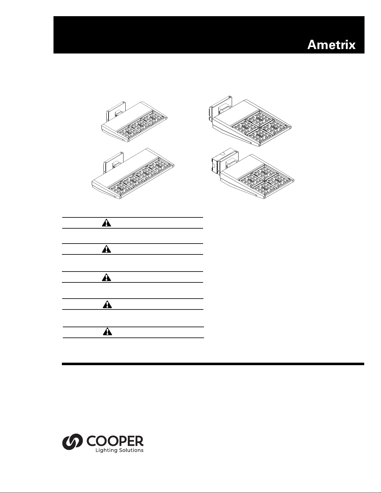
ASYX 2.0
S3-S4-L3-L4-L5-L6 Wall Installation Instructions
IMPORTANT: Read carefully before installing fixture. Retain for future reference.
WARNING
Risk of Electric Shock. Disconnect power at fuse or
circuit breaker before installing or servicing.
WARNING
Risk of Fire/Electric Shock. If not qualified, consult
an electrician.
WARNING
Proper grounding is required to ensure personal
safety.
WARNING
Risk of burn. Use protective gear to ensure to ensure
personal safety.
WARNING
Disconnect all power before proceeding with
installation.
ote:N This product must be installed in accordance
with the applicable installation code by a certified electrician, familiar with the construction and
operation of the product and hazards involved.
ote:N To prevent wiring damage or abrasion, do not
expose wiring to edges of sheet metal or any
sharp objects.
ote:N Fixture in compliance with UL 1598 and UL 8750.
ote:N Wet locations listed.
ote:N MAX ambient temperature 40°C for all fixtures
except L6 which is rated to 30°C ambient.
ote:N All electrical wire from junction box to fixture
head to be provided by others and follow local
codes.
ote:N Ensure mounting surface can support fixture
head(s) and entire fixture assembly.
ote:N Ensure all screws are torqued to proper settings.
Description: The ASYX 2.0 second generation of asymmetric lighting is designed for general ambient illumina-
tion and accenting architectural features. The luminaire allows for both forward and wide distributions as well
four different color temperatures to accommodate any space. The ASYX 2.0 utilizes the patented and highly efficient AccuLED Optics TM system for industry leading performance. IP66 rated
Construction: Heavy-wall die cast aluminum end caps with extruded aluminum housing. Housing fins allow for
air flow and thermal management. Fixture housing is coated using electrostatically charged polyester powder
coat paint for superior protection against fade and wear.
Page 2
COOPER LIGHTING SOLUTIONS IL525007EN ASYX 2.0 Wall S3-S4-L3-L4-L5-L6 Installation Instructions
ASYX 2.0 Installation Instructions - WALL - Types S3-S4-L3-L4-L5-L6
INSTALLATION
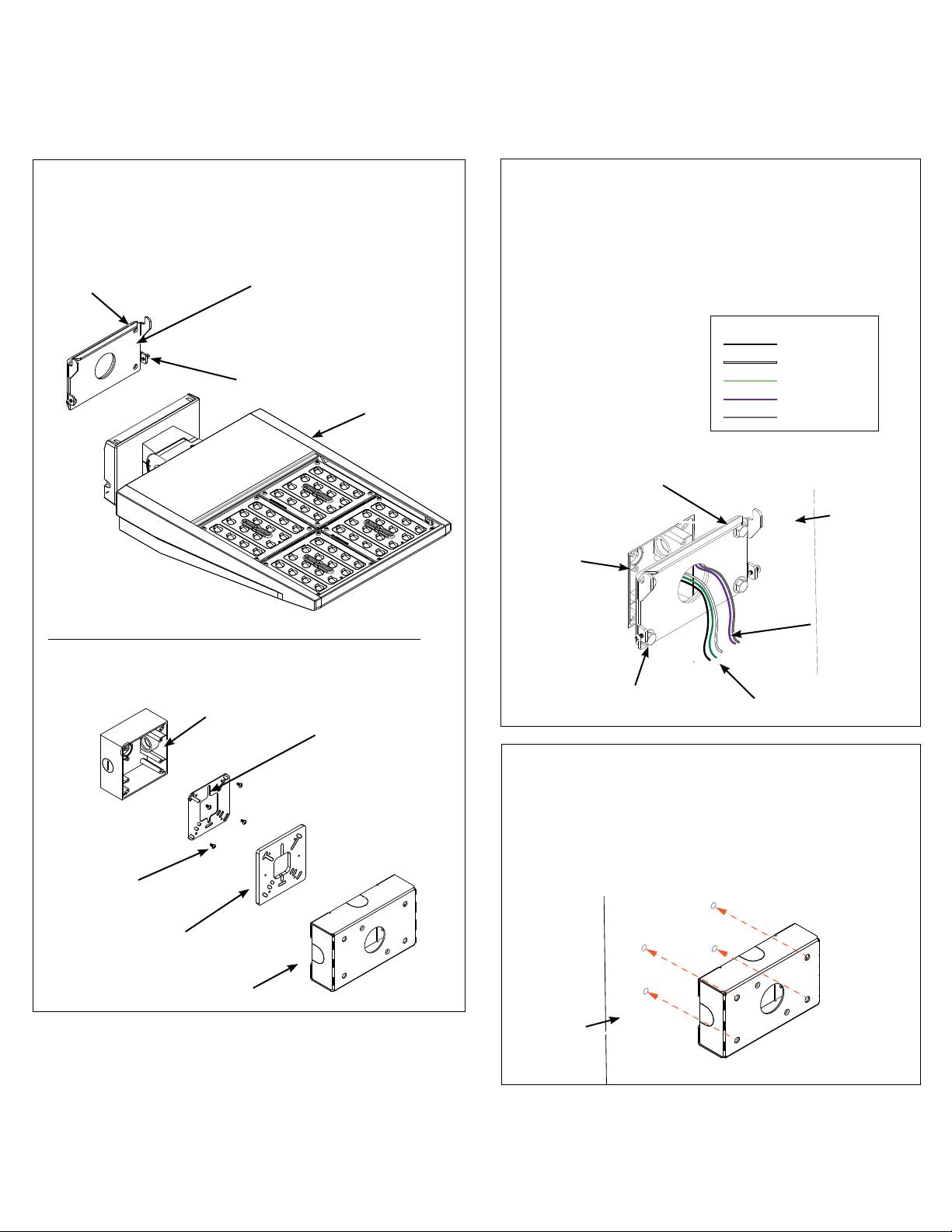
1. Unpack ASYX 2.0 wall fixture and ensure that all
included parts are present (Figure 1.)
Figure 1.
Foam Gasket
on back of
plate
The following are included if the “C” (Surface Mount
Box with Conduit Entry) is selected
Junction Box
Mounting Plate
(2) # 10-32 screws
Fixture Head
Universal
Mounting Plate
(ensure slot is
in the upward
direction)
2. Attach mounting plate using bolts and washers (by
others) at desired wall location over 4”x4” junction
box. Secure wall mount plate to wall with bolts and
washers (determined and supplied by others). Pull
line voltage wires through center hole of mounting
plate. Ensure adequate seal of foam gasket to wall
surface. Silicone caulk around junction box and wall
anchors for wet locations as needed. (Figure 2).
Wiring Table:
Black - Hot
White - Neutral
Green - Ground
Purple - 0-10V (+)
Gray - 0-10V (-)
Figure 2.
Foam Gasket
on back of
plate
Recessed
junction box
(by others)
Bolts
(by others)
Line Voltage
Leads
Wall
Dimming
Leads
(if dimmers
are used)
For Surface Canopy Option (“C”):
3. a Using the Surface Canopy Box as a template, drill
four (4) holes in wall (Figure 3.a). Install appropriate
wall anchors (not supplied).
(4) #10-32
screws
Foam Gasket
Surface
Canopy Box
Note: Not included and to be provided by others:
- Bolts and washers to secure to wall surface
- Waterproof wires nuts
- Wall Anchors
2
Figure 3. a
Wall
IL525007EN
09/29/2015
2 of 5
Page 3

ASYX 2.0 Installation Instructions - WALL - Types S3-S4-L3-L4-L5-L6
COOPER LIGHTING SOLUTIONS IL525007EN ASYX 2.0 Wall S3-S4-L3-L4-L5-L6 Installation Instructions
For Surface Canopy Option (“C”):
3. b A) Attach junction box to wall then Universal
Mounting Plate to junction box using (4) #10-32 flat
head screws. B) Attach Mounting Plate to Surface
Canopy Box via bolt and washers (by others), and
foam gasket. Ensure secure fit. C) Assemble Step A
and Step B together. Surface Canopy Box assembly,
fits over junction box assembly (Figure 3).
(4) #10-32
screws
Foam
Gasket
Junction Box
C)
Surface
Canopy Box
A)
Universal
Mounting Plate
Mounting Plate
Figure 3. b
B)
4. Hang fixture head on mounting plate using steel
cable attached to fixture head. Ensure fixture hangs
securely from mounting plate. Pull electrical wires
through center hole of mounting plate. (Figure 4.)
5. Connect fixture leads to line voltage power, per
local code with waterproof wire nuts. Tuck wires
into junction box. Remove foam bumpers from
fixture (not shown). (Figure 5.)
Figure 5.
Waterproof wire
nuts by others
6. Lift fixture head and hang on hooks on mounting
plate. Tuck steel cable into mounting canopy.
Swing fixture on hooks towards junction box
and level fixture. (Figure 6).
Figure 6.
Figure 4.
3
Steel cable
IL525007EN
09/29/2015
3 of 5
Page 4

ASYX 2.0 Installation Instructions - WALL - Types S3-S4-L3-L4-L5-L6
COOPER LIGHTING SOLUTIONS IL525007EN ASYX 2.0 Wall S3-S4-L3-L4-L5-L6 Installation Instructions
7. Tighten (2) #10-32 screws on side of mounting plate.
(Figure 7).
9. To level and adjust angle of fixture head, loosen
knuckle bolt with socket wrench, and use
an allen wrench to adjust aiming by turning
set screw on top of fixture to desired angle.
Figure 7.
(Figure 9).
Figure 9.
Set Screw
Knuckle
Bolt
8. For the For Surface Canopy Option (“C”) mount application, repeat steps 4 through 7, but mount to Surface
Canopy Box (Step 3) instead of wall. (Figure 8.)
Figure 8.
4
IL525007EN
09/29/2015
4 of 5
Page 5

Cooper Lighting Solutions
is a
registered trademark.
All trademarks are property
of their respective owners.
Cooper Lighting Solutions est une
marque de commerce déposée. Toutes
les autres marques de commerce sont
la propriété de leur propriétaire
respectif.
Cooper Lighting Solutions es una
marca comercial registrada. Todas las
marcas comerciales son propiedad de
sus respectivos propietarios.
Product availability, specifications,
and compliances are subject to
change without notice
La disponibilité du produit, les
spécifications et les conformités
peuvent être modifiées sans préavis
La disponibilidad de productos, las
especificaciones y los cumplimientos
están sujetos a cambio sin previo aviso
Warranties and Limitation of Liability
Please refer to www.cooperlighting.com for our terms and conditions.
Garanties et limitation de responsabilité
Veuillez consulter le site www.cooperlighting.com pour obtenir les conditions générales.
Garantías y Limitación de Responsabilidad
Visite www.cooperlighting.com para conocer nuestros términos y condiciones.
Cooper Lighting Solutions
18001 E. Colfax Avenue
Aurora,
CO 80011
P: 770-486-4800
www.cooperlighting.com
© 2020 Cooper Lighting Solutions
All Rights Reserved
Printed in USA
Imprimé aux États-Unis
Impreso en los EE. UU.
Publication No. IL525007EN
09/29/2015
 Loading...