

Page 1
ADE141259
INS #
Installation Instructions – Aircraft Cable Mount Layout AC-MT
Instructions d’installation – Disposition du montage avec câble
d’aéronef AC-MT
Instrucciones de instalación: Disposición de montaje del cable para
aviación
Page 2
Installation Instructions – Aircraft Cable Mount Layout AC-MT
WARNING
IMPORTANT SAFETY INFORMATION - READ, FOLLOW, AND SAVE ALL SAFETY AND INSTALLATION
Before starting any work ensure that all sources of power are turned OFF. All work must meet local/national electrical
codes and be performed by a certified electrician.
Follow product label information and instructions before installing fixture. Retain installation instructions for future
reference.
Risk of fire, electrical shock, cuts and or other casualty hazards. This product must be installed in accordance with the
applicable
installation code by a person familiar with the construction and operation of the product and the hazards
involved. Cooper Lighting Solutions assumes no responsibility for claims brought about by improper or careless
installation or handling of this product.
Risk of burn. Disconnect power and allow fixture to cool before changing bulb or handling fixture.
Replace lamp only with correct wattage and type of lamp marked on label. DO NOT exceed the maximum wattage listed
on the fixture label.
To prevent wiring damage or abrasion, do not expose wiring to edges of sheet metal or any sharp objects.
INSTRUCTIONS.
NOTICE
If supply wires are located within 3 inches of driver/ballast, use wire rated for at least 90°C (194°F).
Note: Not all option available. Please consult your Cooper Lighting Solutions representative for availability.
Specification and dimension subject to change without notice.
2
Installation Instructions – Aircraft Cable Mount Layout AC-MT
ADE141259 www.cooperlighting.com
Page 3
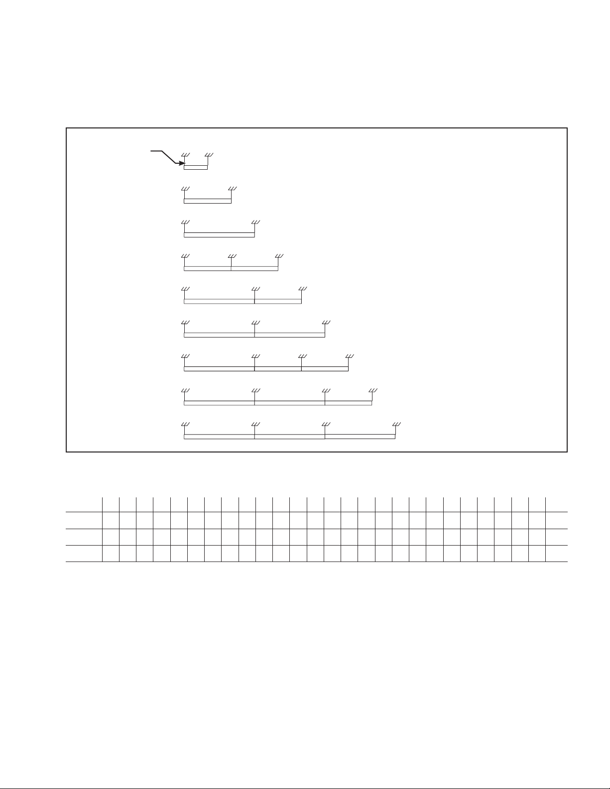
INSTALLATION
Run Length Fixture Breakdown
Fixture Layout and Mount SpacingLength
Power
48” Spacing
4’
96” Spacing
8’
12’
96” Spacing 96” Spacing
16’
20’
24’
144” Spacing
144” Spacing
144” Spacing
Installation Instructions – Aircraft Cable Mount Layout AC-MT
96” Spacing
144” Spacing
144” Spacing
96” Spacing
96” Spacing
28’
144” Spacing 144” Spacing
96” Spacing
32’
36’
144” Spacing 144” Spacing 144” Spacing
For Longer Rows Refer To Table
Quantity of Fixture Length Per Continuous Runs
Continuous Runs are Made up Using 8’-0” and 12’-0” Fixture Lengths as Shown in the Following Table:
Fixture
Length
4’
8’
12’ 44’ 76’28’ 60’ 92’20’ 52’ 84’36’ 68’ 100 ’16’ 48’ 80’32’ 64’ 96’24’ 56’ 88’40’ 72’ 104’ 108’
1
4’
8’
12’
1 1 1 1 1 1 1 1 1
2 2 2 2 2 2 2 2
1
4 4 7 72 2 2 5 5 86 61 4 7
5 83 3 3 6 91
Installation Instructions – Aircraft Cable Mount Layout AC-MT
ADE141259 www.cooperlighting.com
3
Page 4

Instructions d'installation – Disposition du montage avec câble d'aéronef AC-MT
AVERTISSEMENT
INFORMATIONS IMPORTANTES SUR LA SÉCURITÉ - LISEZ, SUIVEZ ET CONSERVEZ TOUTES LES CONSIGNES DE
Avant de commencer toute opération, assurez-vous que toutes les sources d'alimentation sont hors tension. Toutes les
tâches effectuées doivent être conformes aux codes de l'électricité locaux et nationaux et doivent être accomplies par
un électricien autorisé.
Suivez les informations qui se trouvent sur l'étiquette du produit ainsi que les instructions avant d'installer le luminaire.
Conservez les instructions d'installation pour consultation ultérieure.
Risques d'incendie, de décharge électrique, de coupures et autres dangers de blessure. Ce produit doit être installé
conformément au code d'installation applicable par une personne à l'aise avec la construction et le fonctionnement du
produit et avec les dangers que cela implique. Cooper Lighting Solutions n'assume aucune responsabilité pour les
réclamations causées par l'installation ou la manipulation incorrecte ou négligente de ce produit.
Risque de brûlures. Débranchez l'alimentation électrique et laissez refroidir le luminaire avant de le manipuler ou de
changer l'ampoule.
Remplacez l'ampoule seulement avec le bon type et la bonne puissance d'ampoule, tel qu'indiqué sur l'étiquette. NE
dépassez PAS la puissance maximale indiquée sur l'étiquette du luminaire.
Afin d'éviter les dommages ou l'abrasion des câblages, ne les exposez pas aux bords de feuilles de métal ou de tout
autre objet tranchant.
SÉCURITÉ ET LES INSTRUCTIONS D'INSTALLATION.
AVIS
fils d’alimentation sont situés à moins de 76,2 mm (3 po) du pilote/ballast, utilisez un fil classifié pour tolérer un
Si les
minimum de 90°C (194°F).
Remarque: Les options ne sont pas toutes offertes. Veuillez consulter votre représentant Cooper Lighting Solutions
pour la disponibilité. Les spécifications et dimensions sont indiquées sous réserve de modifications.
4
Instructions d'installation – Disposition du montage avec câble d'aéronef AC-MT
ADE141259 www.cooperlighting.com
Page 5

Instructions d'installation – Disposition du montage avec câble d'aéronef AC-MT
INSTALLATION
Répartition des longueurs des luminaires
Schéma du luminaire et espacement de montageLongueur
Alimentation
122cm
(4 pi)
244cm
(8 pi)
366cm
(12 pi)
488cm
(16 pi)
610cm
(20 pi)
732cm
(24 pi)
853cm
(28 pi)
975cm
(32 pi)
11 m
(36 pi)
Espacement de 1,2m (48po)
Espacement de
2,4m (96po)
Espacement de
3,6m (144po)
Espacement de
2,4m (96po)
Espacement de
3,6m (144po)
Espacement de
3,6m (144po)
Espacement de
3,6m (144po)
Espacement de
3,6m (144po)
Espacement de
3,6m (144po)
Pour des rangées plus longues consultez le tableau
Espacement de
2,4m (96po)
Espacement de
2,4m (96po)
Espacement de
3,6m (144po)
Espacement de
2,4m (96po)
Espacement de
3,6m (144po)
Espacement de
3,6m (144po)
Espacement de
2,4m (96po)
Espacement de
2,4m (96po)
Espacement de
3,6m (144po)
Nombre de luminaires par longueur continuelle
Les longueurs continuelles sont constituées de longueurs de luminaires de 244cm (8 pi) et de 366cm (12 pi)
comme indiqué dans le tableau suivant:
Longueur
du luminaire
122cm
(4 pi)
244cm
(8 pi)
366cm
(12 pi)
244cm
366cm
122cm
(4 pi)
1
(8 pi)
488cm
(12 pi)
1 1 1 1 1 1 1 1 1
610cm
(16 pi)
(20 pi)
2 2 2 2 2 2 2 2
1
732cm
(24 pi)
853cm
(28 pi)
975cm
(32 pi)
11m
(36 pi)
Instructions d'installation – Disposition du montage avec câble d'aéronef AC-MT
12m
(40 pi)
13m
(44 pi)
15m
(48 pi)
16m
(52 pi)
18m
17m
(60 pi)
(56 pi)
4 4 7 72 2 2 5 5 86 61 4 7
5 83 3 3 6 91
ADE141259 www.cooperlighting.com
19m
(64 pi)
21m
(68 pi)
22m
(72 pi)
23m
(76 pi)
24m
(80 pi)
25m
(84 pi)
26m
(88 pi)
28m
(92 pi)
29m
(96 pi)
30m
(100 pi)
32m
(104 pi)
33m
(108 pi)
5
Page 6

Instrucciones de instalación: Disposición de montaje del cable para aviación
ADVERTENCIA
INFORMACIÓN IMPORTANTE SOBRE SEGURIDAD: LEA, SIGA Y GUARDE TODAS LAS INSTRUCCIONES DE
INSTALACIÓN Y SEGURIDAD.
Antes de comenzar los trabajos, verifique que estén desconectadas todas las fuentes de alimentación. Todos los
trabajos deben cumplir con los códigos eléctricos locales/nacionales y los debe realizar un electricista certificado.
Siga la información y las instrucciones en la etiqueta del producto antes de instalar la luminaria. Conserve las
instrucciones de instalación para referencia futura.
Riesgo de inflamabilidad, descarga eléctrica, cortes y otros riesgos de muerte. Una persona con conocimientos sobre la
construcción y el funcionamiento del producto y los riesgos implicados debe instalar este producto de conformidad con
el código de instalación aplicable. Cooper Lighting Solutions no se responsabiliza por los reclamos presentados respecto
de la instalación y la manipulación inapropiadas o negligentes de este producto.
Riesgo de quemaduras. Desconecte la alimentación y deje que la luminaria se enfríe antes de cambiar la bombilla o
manipular la luminaria.
Coloque nuevamente la lámpara con el vataje correcto y el tipo de lámpara que se indica en la etiqueta. NO exceda el
vataje máximo que se indica en la etiqueta de la luminaria.
Para evitar abrasiones o daños en el cableado, no exponga los cables a bordes de chapa o cualquier otro objeto filoso.
AVISO
Si los cables de alimentación se encuentran a 3" (76,2 mm) del balasto, utilice cables aptos para al menos 90°C (194°F).
Nota: No
todas las opciones están disponibles. Consulte la disponibilidad con su Representante de Cooper Lighting
Solutions. Las especificaciones y las dimensiones están sujetas a cambios sin previo aviso.
6
Instrucciones de instalación: Disposición de montaje del cable para aviación
ADE141259 www.cooperlighting.com
Page 7

Instrucciones de instalación: Disposición de montaje del cable para aviación
INSTALACIÓN
Longitud de paso de la tensión disruptiva de las luminarias
Disposición de la luminaria y espacio de montajeLongitud
Alimentación
1,21 m
(4 pies)
2,44 m
(8 pies)
3,66 m
(12 pies)
4,87 m
(16 pies)
6,09 m
(20 pies)
7,31 m
(24 pies)
8,53 m
(28 pies)
9,75 m
(32 pies)
10,97 m
(36 pies)
Espacio de 12,20 cm (48 pulgadas)
Espacio de 243cm
(96 pulgadas)
Espacio de 365cm
(144 pulgadas)
Espacio de 243cm
(96 pulgadas)
Espacio de 365cm
(144 pulgadas)
Espacio de 365cm
(144 pulgadas)
Espacio de 365cm
(144 pulgadas)
Espacio de 365cm
(144 pulgadas)
Espacio de 365cm
(144 pulgadas)
Espacio de 243cm
(96 pulgadas)
Espacio de 243cm
(96 pulgadas)
Espacio de 365cm
(144 pulgadas)
Espacio de 243cm
(96 pulgadas)
Espacio de 365cm
(144 pulgadas)
Espacio de 365cm
(144 pulgadas)
Para rieles de mayor longitud, remítase a la tabla
Espacio de 243cm
(96 pulgadas)
Espacio de 243cm
(96 pulgadas)
Espacio de 365cm
(144 pulgadas)
Cantidad de luminarias por pasos de longitud continuos
Los pasos continuos se arman usando longitudes de luminarias de 4'0" y 8'0" como se muestra en la
siguiente tabla:
Longitud de
la luminaria
1,21 m
(4 pies)
2,44 m
(8 pies)
3,66 m
(12 pies)
1,21 m
(4 pies)
1
3,66 m
2,44 m
(12
(8 pies)
pies)
1 1 1 1 1 1 1 1 1
6,09
4,87
m (16
pies)
1
7,31 m
m (20
(24
pies)
pies)
2 2 2 2 2 2 2 2
Instrucciones de instalación: Disposición de montaje del cable para aviación
8,53 m
(28
pies)
9,75 m
(32
pies)
10,97
m (36
pies)
12,19
m (40
pies)
13,41
m (44
pies)
14,63
m (48
pies)
15,85
m (52
pies)
ADE141259 www.cooperlighting.com
17,07
18,19
m (56
m (60
pies)
pies)
4 4 7 72 2 2 5 5 86 61 4 7
20,73
19,51
m (64
pies)
5 83 3 3 6 91
m (68
pies)
m (72
pies)
m (76
pies)
24,39
m (80
pies)
23,16
21,95
25,60
m (84
pies)
26,82
m (88
pies)
28,04
m (92
pies)
29,26
m (96
pies)
30,48
m (100
pies)
31,70
m (104
pies)
32,92
m (108
pies)
7
Page 8

Cooper Lighting Solutions is
a
registered trademark.
All trademarks are property
of their respective owners.
Cooper Lighting Solutions est une
marque de commerce déposée. Toutes
les autres marques de commerce sont
la propriété de leur propriétaire
respectif.
Cooper Lighting Solutions es una
marca comercial registrada. Todas las
marcas comerciales son propiedad de
sus respectivos propietarios.
Warranties and Limitation of Liability
Please refer to www.cooperlighting.com for our terms and conditions.
Garanties et limitation de responsabilité
Veuillez consulter le site www.cooperlighting.com pour obtenir les conditions générales.
Garantías y Limitación de Responsabilidad
Visite www.cooperlighting.com para conocer nuestros términos y condiciones.
Cooper Lighting Solutions
18001
East Colfax Avenue
Aurora, CO 80011
www.cooperlighting.com
© 2020 Cooper Lighting Solutions
All Rights Reserved
Printed in USA
Imprimé aux États-Unis
Impreso en los EE. UU.
Publication No. ADE141259
Rev Date: October 2014
 Loading...