

Page 1
VISION FLOOD ARCHITECTURAL FLOOD LUMINAIRE
TM
Page 2
VISION FLOOD
ARCHITECTURAL FLOOD LUMINAIRE
- Facade
- Sign
- Landscape
– Architectural Highlighting
– General Area Illumination
FLUENT FORM
VISION Flood’s cylindrical form blends effortlessly to architectural and landscape environments.
Available in wattages up to 1000 watt Metal Halide and in two (2) housing sizes, VISION Flood offers
properly scaled solutions for any floodlighting application.
EXCEPTIONAL DESIGN
Designed for sustaining quality, VISION Flood’s precisely engineered die-cast aluminum
housing and door incorporate IP65 rated gasketing strategies, while the heavy duty knuckle provides
infinite aiming flexibility and lock-down strength tested to withstand 3G of vibration.
OPTICAL FLEXIBILITY
Designed to offer community friendly optical control, VISION Flood optics focus lamp output
into defined rectangular patterns while controlling direct visibility of the lamp, a root cause of glare
and light pollution. Six (6) available optical systems provide maximum design flexibility, while a
broad array of light control accessories provide supplemental cutoff control.
Page 3
Page 4
FLOODLIGHTING FUNDAMENTALS
E D
2
COS (x)
X=45°
45°
I=707 cd
D
=
1
0
'
5 fc (10')
2
COS (45°)
=
707 candela
E=fc
I=
E D
2
COS (x)
X=30°
30°
I=
577 cd
5 fc (10')
2
COS (30°)
D
=
1
0
'
=
577 candela
E=5 fc
I=
E D
2
COS (x)
X=30°
30°
I=2,310 cd
5 fc (20')
2
COS (30°)
D
=
2
0
'
=
2,310 candela
E=5 fc
I=
E D
2
COS (x)
X=30°
I=
57
7 cd
5 fc (10')
2
COS (30°)
D
=
1
0
'
=
577 candela
E=5 fc
I=
30°
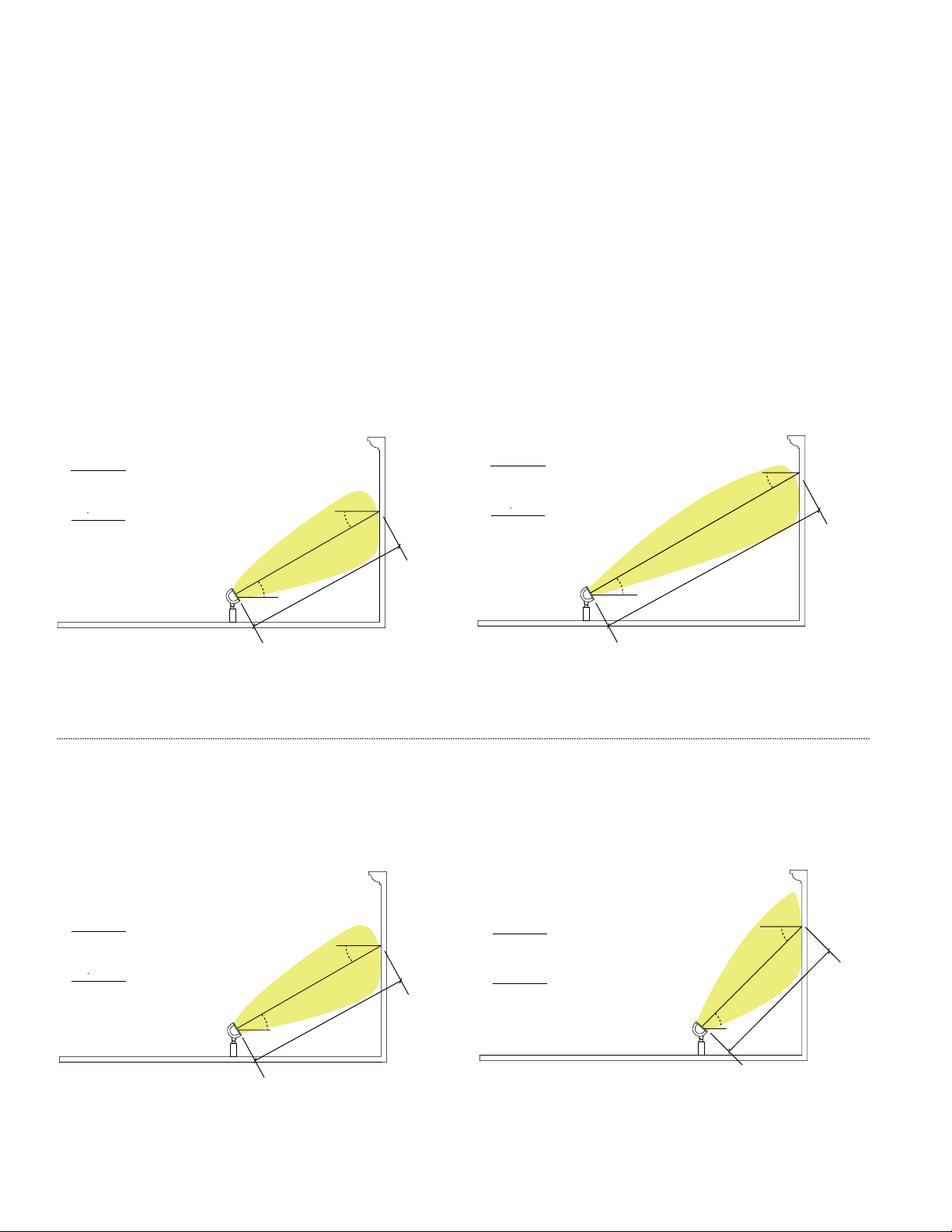
- Inverse Square Cosine Law
Footcandle levels are ultimately dependent upon the projected distance, aiming angle, and luminous intensity of a lamp/reflector combination.
A cursory understanding of the equation which relates these variables provides insights to proper design technique and distribution selection.
INVERSE SQUARE COSINE LAW
2
E=I cos (x)/D
Illuminance (Footcandles, fc) = Luminous Intensity (Candelas, Cd) * cos (incident angle X) / Distance
Holding other variables constant, as the projected distance increases from the luminaire to the surface being illuminated, a greater amount
of luminous intensity (I, Candela) is required to sustain an equal illuminance (E, Footcandle) level.
-or-
2
Holding incident angle X constant at 30˚ while increasing the projected distance D from 10' to 20' requires an increase in candela from
577 to 2310 respectively to sustain an equal 5 footcandles (fc) of illumination at the target point.
The incident angle as measured from a luminaire’s directed intensity to the target surface normal also plays a significant role in determining
illuminance values. Holding other variables constant as the incident angle from the target surface to the projected aiming line increases, so does
the amount of luminous intensity (I, Candela) required to sustain an equal illuminance value.
Holding projected distance D constant at 10' while increasing incident angle X from 30˚ to 45˚ requires an increase in candela from
577 to 707 respectively to sustain an equal 5 footcandles (fc) of illumination at the target point.
3
VISION FLOOD Architectural Flood Luminaire
Page 5
NEMA Beam Field Angle Description +
Classification Range Setback
1 10-18° Narrowest Beam, Long Setback
2 18-29° Narrow Beam, Long Setback
3 29-46° Narrow Beam, Long Setback
4 46-70° Medium Beam, Medium Setback
5 70-100° Medium Beam, Medium Setback
6 100-130° Wide Beam, Shorter Setback
7 130°-Greater Widest Beam, Short Setback
FLOODLIGHTING TERMINOLOGY
90°
60°
80°
70°
50°
40°
30°
45°
0°
Beam Angle
1
0
,
0
0
0
c
d
1
5
,
0
0
0
c
d
2
0
,
0
0
0
c
d
2
5
,
0
0
0
c
d
3
0
,
0
0
0
c
d
3
5
,
0
0
0
c
d
4
0
,
0
0
0
c
d
4
5
,
0
0
0
c
d
5
0
,
0
0
0
c
d
5
,
0
0
0
c
d
Field Angle
90°
60°
80°
70°
50°
40°
30°
45°
20°
10°
20°
10°
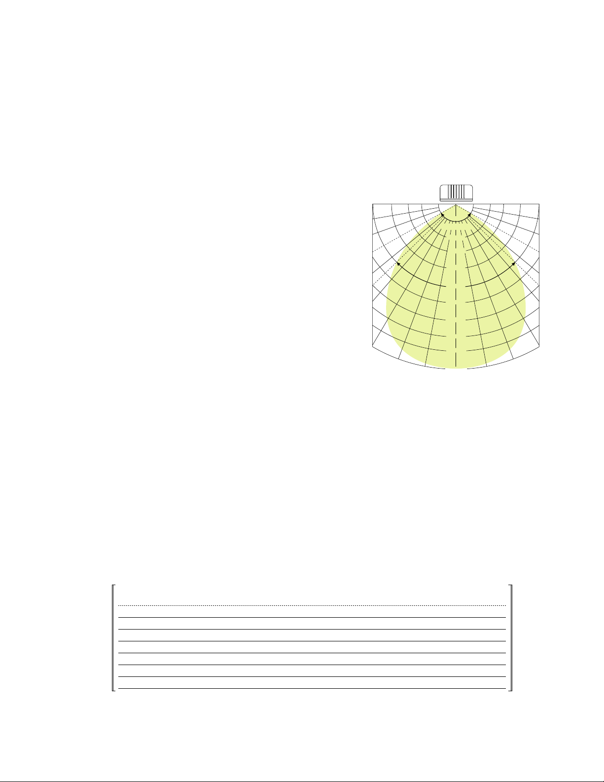
- Floodlighting Terminology
- NEMA [IES] Classifications
FLOODLIGHTING TERMINOLOGY
Ever wonder how NEMA (H x V) Classifications are derived, or how they relate
to the performance and design application of a floodlighting distribution?
How about beam and field angles, and maximum candela values?
- Maximum Candela is defined as the maximum candela value emitted
from the luminaire in any given direction.
- Beam angle is defined as the included angle between points of 50%
of Maximum Candela.
- Field Angle is defined as the included angle between points of 10%
of Maximum Candela.
As an example, a distribution with a 50,000 Cd maximum candela value
as shown in the intensity distribution graph to the right (FIG. 1) would have a
Beam Angle defined by the included angle of 25,000 Cd values, and a Field
Angle defined by the included angle of 5,000 Cd values.
FIG. 1
EXAMPLE
Max Candela = 50,000 Cd
Candela Value defining Beam Angle = (50% * 50,000 Cd) = 25,000 Cd
Candela Value defining Field Angle = (10% * 50,000 Cd) = 5,000 Cd
Beam Angle = 90°
Field Angle = 120°
NEMA [IES] CLASSIFICATIONS
NEMA classifications are extrapolated from the table below and are determined by a distribution’s Field Angle. This relative classification is used
to describe the general shape and application of a distribution. NEMA classifications are used to classify both the horizontal and vertical
components of a floodlight distribution.
The example distribution in FIG. 1 above would have a NEMA Classification of 6 as the 120° Field Angle falls between the 100-130° range.
VISION FLOOD Architectural Flood Luminaire
4
Page 6

Without Internal Louvers
With Internal Louvers
VISION Flood offers a host of beam control options that limit
Without External Louvers
With External Louvers
unwanted stray light and control direct viewing
SPILL + GLARE CONTROL
- Internal Louvers
- External Grid Louvers
- Top Visor
- 4 Sided Shield
- Barn Doors
- Rectangular Beam Patterns
of the lamp source.
Limiting the amount of stray light which falls beyond the boundaries of the intended target is not only good design practice, but is increasingly
a mandate of local and state adopted lighting ordinances. The VISION Flood series offers a family of beam control options to limit unwanted stray
light and control direct viewing of the lamp, a common source of discomfort and disability glare.
INTERNAL LOUVERS
Standard on Narrow Spot and Narrow Flood
distributions, integral ring louver controls lamp
glare while eliminating spill light outside the
main beam.
EXTERNAL GRID LOUVERS
Designed to control lamp glare and spill light
while maintaining beam efficiency. Useful when
aiming direction or intended target lies in close
proximity to pedestrian and/or motor vehicle
activity. Mounts to accessory channel in
doorframe. Compatible with all distributions.
Available on VFM only.
5
VISION FLOOD Architectural Flood Luminaire
Page 7
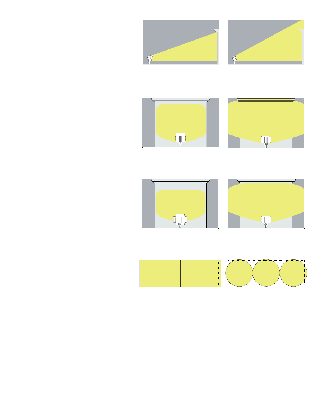
Without Top Visor
TOP VISOR
With Top Visor
Without 4-Sided Shield
With 4-Sided Shield
Without Barn Doors
With Barn Doors
Typical Round Beam Patterns
Rectangular Beam Patterns
Controls excess spill and glare on top portion
of distribution. Especially useful in uplighting
applications to limit light travel above an
intended wall surface or sign. Mounts to
accessory channel in doorframe. Compatible
with all distributions.
4-SIDED SHIELD
Controls lamp glare and spill light in all
directions. Useful when aiming direction or
intended target lies in close proximity to
pedestrian and/or motor vehicle activity.
Mounts to accessory channel in doorframe.
Compatible with all distributions. Available on
VFM only.
BARN DOORS
Four (4) independently mounted and adjustable
doors control cutoff angles in all directions,
allowing custom distribution control. Compatible
with all distributions.
RECTANGULAR BEAM PATTERNS
Structures, signs, and other various objects which
dominate our visual landscape are largely defined
by straight lines and planar surfaces. Lighting
these objects with rectangular distributions
eliminates excess spill light while maintaining
optimal uniformity.
Rectangular beams produce more
uniform coverage, resulting in reduced
fixture counts and less stray light
spilling beyond the intended target.
Typical round patterns create shadows in
corners, requiring closer fixture
spacings. Uniformity is compromised.
6
VISION FLOOD Architectural Flood Luminaire
Page 8
Area Target Surface Average Target
Description Finish Illuminance
Bright Surroundings Light Surfaces 5 fc
Bright Surroundings Medium Light Surfaces 7 fc
Bright Surroundings Dark Surfaces 10 fc
Dark Surroundings Light Surfaces 2 fc
Dark Surroundings Medium Light Surfaces 3 fc
Dark Surroundings Medium Dark Surfaces 4 fc
Dark Surroundings Dark Surfaces 5 fc
NEMA Beam Field Angle Maximum
Lamp Lamp Beam IES (50% Max. Candela) (10% Max. Candela) Candela Total
Wattage Type Pattern Type in Degrees in Degrees Value Efficiency
175W MH
1
ED-17 Narrow Spot 1 H x 3 V 7 H x 15 V 17 H x 33 V 102,434 60%
Narrow Flood 3 H x 3 V 16 H x 23 V 30 H x 45 V 53,892 71%
Medium Flood 5 H x 3 V 52 H x 18 V 74 H x 41 V 25,698 84%
Wide Flood 7 H x 6 V 70 H x 55 V 132 H x 103 V 8,346 84%
Vertical Flood 7 H x 6 V 98 H x 58 V 147 H x 130 V 5,420 71%
Horizontal Spot 6 H x 6 V 80 H x 27 V 111 H x 120 V 10,694 83%
400W MH
2
BT-37 Narrow Spot 1 H x 2 V 8 H x 16 V 14 H x 27 V 304,593 41%
Narrow Flood 2 H x 3 V 12 H x 19 V 23 H x 36 V 162,701 50%
Medium Flood 4 H x 4 V 22 H x 23 V 48 H x 49 V 92,191 81%
Wide Flood 7 H x 6 V 86 H x 58 V 137 H x 101 V 20,734 81%
Vertical Flood 7 H x 7 V 106 H x 57 V 145 H x 139 V 14,761 74%
Horizontal Spot 5 H x 5 V 86 H x 15 V 94 H x 90 V 34,463 61%
1000W MH
3
BT-37 Narrow Spot 1 H x 4 V 5 H x 16 V 13 H x 48 V 633,201 51%
Narrow Flood 2 H x 4 V 14 H x 27 V 29 H x 55 V 279,879 53%
Medium Flood 4 H x 4 V 23 H x 33 V 53 H x 68 V 197,476 78%
Wide Flood 7 H x 6 V 85 H x 74 V 139 H x 116 V 52,625 83%
Vertical Flood 7 H x 7 V 111 H x 55 V 152 H x 135 V 42,981 76%
Horizontal Spot 6 H x 5 V 85 H x 16 V 105 H x 96 V 99,290 64%
150W HPS
4
ED-17 Narrow Spot 1 H x 4 V 9 H x 23 V 17 H x 46 V 74,261 61%
Narrow Flood 3 H x 4 V 21 H x 31 V 31 H x 57 V 41,007 70%
Medium Flood 5 H x 4 V 49 H x 27 V 77 H x 54 V 23,522 81%
Wide Flood 7 H x 6 V 8 x 69 V 136 H x 109 V 7,567 79%
Vertical Flood 7 H x 6 V 99 H x 55 V 145 H x 126 V 6,331 69%
Horizontal Spot 5 H x 6 V 77 H x 14 V 95 H x 112 V 18,237 84%
400W HPS
5
ED-18 Narrow Spot 1 H x 4 V 6 H x 20 V 13 H x 47 V 260,454 48%
Narrow Flood 2 H x 4 V 15 H x 27 V 27 H x 52 V 112,314 44%
Medium Flood 4 H x 5 V 23 H x 33 V 54 H x 71 V 86,573 78%
Wide Flood 7 H x 6 V 88 H x 80 V 140 H x 117 V 21,630 80%
Vertical Flood 7 H x 7 V 102 H x 60 V 145 H x 137 V 20,686 75%
Horizontal Spot 6 H x 5 V 81 H x 15 V 102 H x 100 V 44,433 62%
1
If using a 100W MH lamp, apply a 0.629 scaling factor to the 175W MH maximum candela values.
2
If using a 250W MH lamp, apply a 0.569 scaling factor to the 400W MH maximum candela values.
3
If using a 750W MH lamp, apply a 0.745 scaling factor to the 1000W MH maximum candela values.
4
If using a 100W HPS lamp, apply a 0.594 scaling factor to the 150W HPS maximum candela values.
5
If using a 250W HPS lamp, apply a 0.55 scaling factor to the 400W HPS maximum candela values.
DESIGN GUIDE
- Illumination Recommendations
- Beam Pattern Information
ILLUMINATION RECOMMENDATIONS
Effective floodlighting design is a complex and subjective task. Results are heavily dependent upon surrounding light levels, surface finish of the
intended target, spectral color distribution of the lamp source, mounting location allowances, and viewers perceptions.
The following table lists IESNA (Illuminating Engineering Society of North America) recommended illuminance levels for the floodlighting of
buildings and monuments.
Cooper Lighting Application Engineers are available to assist in providing design layouts, aiming diagrams, and illuminance plots for your next
floodlighting project. Consult your INVUE Lighting Systems Representative for more information.
BEAM PATTERN INFORMATION
7
VISION FLOOD Architectural Flood Luminaire
Page 9

COLOR CAPABILITIES
Infusing color to a visual landscape elicits attention,
emotion, and intrigue.
COLOR CAPABILITIES
VISION Flood can be specified with one of four (4) standard color gels: Deep Green, Bright Blue, Red or Warm Orange. Dichoric glass filter options
and custom colors are also available. Consult your INVUE Lighting Systems Representative for more information.
WITH COLOR FILTER
ADAPTER
METAL HALIDE
BRIGHT BLUE FILTER
HIGH PRESSURE SODIUM
RED FILTER
METAL HALIDE
DEEP GREEN FILTER
HIGH PRESSURE SODIUM
BRIGHT BLUE FILTER
METAL HALIDE
WARM ORANGE FILTER
HIGH PRESSURE SODIUM
DEEP GREEN FILTER
METAL HALIDE
RED FILTER
HIGH PRESSURE SODIUM
WARM ORANGE FILTER
NOTE: Color representations are for comparative purposes only, and do not imply achieved color in application which is dependent upon lamp
source, optic, and target surface properties.
VISION FLOOD Architectural Flood Luminaire
8
Page 10

Page 11

Page 12

With six (6) uniquely shaped optical distributions, the VISION Flood
provides targeted lighting solutions for facade, sign, landscape,
architectural highlighting, and more.
OPTICAL CONFIGURATIONS
All optical systems are fully interchangeable, featuring toolless release fasteners and wire connectors.
NARROW SPOT [NS]
The Narrow Spot distribution creates a
narrow column of light, free from spill light
outside the main beam. Ideal for
illuminating columns, small architectural
details, tall trees, high mount signage, and
flagpoles. Generally used with farther
setbacks.
NARROW FLOOD [NF]
Designed for applications where a tight,
symmetrical beam is required, often with
farther setbacks. Ideal for longer distance
facade highlighting, flag lighting, and high
mount signage.
MEDIUM FLOOD [MF]
Designed for applications requiring a wider,
rectangular pattern of uniform illumination.
Ideal for medium setback floodlighting of
facades, signage, general landscape, and
indirect canopy lighting.
8°
16°
12°
19°
22°
23°
11
VISION FLOOD Architectural Flood Luminaire
Page 13

WIDE FLOOD [WF]
VISION Flood Premium 95% Reflective Surface
Competitor's Standard 86% Reflective Surface
95%
100%
86%
Designed for applications requiring a wide
rectangular pattern of uniform illumination.
Generally used with shorter setbacks to
floodlight large facades, signage, and broad
leaf foliage. Also effective in pole mount
applications for general area illumination.
VERTICAL FLOOD [VF]
Designed to illuminate tall facades and
signage in limited setback applications.
In pole mount applications, the Vertical
Flood produces a broad forward throw
distribution ideal for area lighting.
OPTICAL CONFIGURATIONS
86°
106°
58°
57°
HORIZONTAL SPOT [HS]
The Horizontal Spot optic creates a
concentrated pattern that is wide
horizontally, yet tight vertically. Ideal for
lighting wide ground mount signage, and
highlighting wide building-mounted objects
and signage. Also ideal in wall mount and
short setback applications to graze a wall
surface, creating depth and contrast that
accentuates architectural details.
PREMIUM MATERIALS
A commitment to using premium
95% reflective aluminum sheet for
all reflective faces allows for efficiency
gains of up to 10%.
86°
15°
PREMIUM MATERIAL
Premium material reflects a higher intensity
of light in a more controllable fashion.
STANDARD MATERIAL
Standard material reflects a lower intensity
of light.
12
VISION FLOOD Architectural Flood Luminaire
Page 14

VISION Flood luminaires provide unsurpassed levels of protection
IP 6 5
Ingress Protection Complete No moisture
protection within fixture
against after a constant
dust entry 100L/min. pressure
jet spay from all
practical directions
against entry of airborne contaminants. With a certified IP65 fixture
rating, dust, insects, and moisture simply have no chance of
penetrating the fixture’s outer enclosure.
FIXTURE SEALING
- IP Rating
IP RATING
"IP" stands for Ingress Protection and is a rating system established
by the European organization IEC, International Electrotechnical
Commission. Over 50 countries strong, this organization publishes
international standards for electrical products and other related
technologies. The two numbers proceeding the "IP" individually callout
the fixture’s protection ratings against airborne particulates and moisture
13
VISION FLOOD Architectural Flood Luminaire
respectively.
Page 15

VFS VFM
Metal Halide 50, 70, 100, 175W 175, 250, 400, 1000W
Pulse Start Metal Halide 250, 320, 350, 400, 750W
High Pressure Sodium 50, 70, 100, 150W 150, 250, 400W
LAMP SOURCE OPTIONS
5°
15°
10°
20°
Limited
Incremental
Aiming
Infinite Aiming
LAMP OPTIONS
VISION Flood optical systems are offered with a variety of high efficiency lamp sources.
- Metal Halide | Pulse Start Metal Halide
- High Pressure Sodium
METAL HALIDE/
PULSE START METAL HALIDE
Produces a whitish-blue light, excellent
color rendition up to 92 CRI, and high
efficacy (lumens per watt).
APPLICATION: Generally, Metal Halide
sources best compliment concrete
surfaces, light colored masonry, foliage,
and bright colored objects and surfaces.
HIGH PRESSURE SODIUM
Produces an yellowish-orange light with
high efficacy (lumens per watt) and long
life.
APPLICATION: HPS sources add a
richness and warmth that best
complements brick, wood, and dark
colored masonry or stone surfaces.
AIMING VERSATILITY
AVAILABLE LAMP OPTIONS PER
HOUSING SIZE
- Taper Lock Knuckle
- Competitor’s Tooth Lock Knuckle
TAPER-LOCK KNUCKLE
The taper-lock knuckle featured on all VISION Flood luminaires is a
powerful differentiator that insures ultimate aiming flexibility, and
rock solid strength.
VISION Flood’s taper-lock mechanism allows for infinite vertical aiming
adjustment within the fixture’s aiming range. This feature empowers
Designers with ultimate aiming discretion, and allows installers or end
users the ability to visually optimize the distribution once installed to
deliver exacting performance.
COMPETITOR’S TOOTH LOCK KNUCKLE
Competitors tooth lock knuckle designs notably limit the vertical
aiming adjustment of the luminaire, making it more difficult to
achieve desired uniformity ratios and cutoff control. Typical tooth
lock designs are limited to adjustments in increments of 5 to 7.5°.
14
VISION FLOOD Architectural Flood Luminaire
Page 16

Page 17

Page 18

HOUSING
One-piece, die-cast aluminum housing maintains a nominal .125" thickness to endure the
toughest environments while maintaining precise tolerance control.
DOOR
Die-cast aluminum door maintains a nominal .125" thickness and features concealed
hinging to the housing. Door is secured with four (4) tamper resistant recessed stainless
steel allen head fasteners. Door frame features an integral accessory channel for the
mounting of optional light control accessories. Doorframe seals to housing with a
continuous extruded silicone gasket. Lens is impact resistant .180" thick tempered clear
flat glass, sealed to the door with a one-piece silicone gasket.
PRODUCT SPECIFICATIONS
- Features + Benefits
OPTICAL ASSEMBLY
Choice of six (6) high efficiency optical systems constructed of premium 95% reflective
anodized aluminum sheet, or bright specular anodized polished spun aluminum. Available
distributions include Narrow Spot, Narrow Flood, Medium Flood, Wide Flood, Horizontal
Spot, and Vertical Flood. All reflector modules feature toolless removal, quick disconnect
wire connections, and are field interchangeable. Medium housing (VFM) optics feature
mogul-base lampholders while small housing (VFS) optics feature medium-base
lampholders.
KNUCKLE
Heavy-duty die-cast aluminum knuckle utilizes a taper-lock adjustment mechanism for
both solid engagement and infinite aiming adjustment. Knuckle adjustment is made via
one (1) captive stainless steel allen head fastener consistent with doorframe fasteners.
Tested to sustain 3G of vibration without loosing aiming position. VFS knuckle features a
3/4" NPT nipple on bottom surface for rigid attachment to available mounting
accessories. Optional slipfitter mount available for VFS. VFM lower knuckle slip-fits over
a standard 2" pipe size (2 3/8" O.D.) tenon.
ELECTRICAL COMPONENTS
High Power Factor (HPF) ballast components are strategically located and heat sunk to
the housing for cooler operation and longer life. The VFS housing is rated for 40°C
(104°F) ambient environments.
17
VISION FLOOD Architectural Flood Luminaire
Page 19

FINISH
IP65 Rated
CSA Listed
Certifications
U.L. 1598 Listed 3G Vibration Rated
ISO 9001
25°C Ambient [VFM]
40°C Ambient [VFS]
14" [356 mm]
7 1/2"
[191 mm]
10"
[254 mm]
X
X=2 15/16"
[75 mm]
23" [584 mm]
16 1/2"
[419 mm]
7 11/16"
[196 mm]
11 13/64" [284 mm]
Housing and arm finished in a 5 stage
premium TGIC polyester powder coat paint,
2.5 mil nominal thickness for superior
protection against fade and wear. Standard
colors include black, bronze, grey, white, dark
platinum, and graphite metallic. RAL and
custom color matches available. Consult your
INVUE Lighting Systems Representative for
more information.
DIMENSIONS
Vision Flood Small [VFS] Vision Flood Medium [VFM]
18
VISION FLOOD Architectural Flood Luminaire
Page 20

VFS MOUNTING OPTIONS + SPECIFICATIONS
3/4" [20 mm] Dia.
5"
[127 mm]
4 1/4"
[108 mm]
4" [102 mm]
4 1/2"
[115 mm]
3/4" [20 mm] Dia.
6" [152 mm]
Sq. Bolt Pattern
5/16" [8 mm]
Dia.
18"
[457 mm]
3/4" [20 mm] Dia.
24" [610 mm]
3/4" [20 mm] Dia.
6 1/2"
[165 mm] Sq.
15" [381 mm]
5/16" [8 mm] Dia.
3/4" [20 mm] Dia.
4" [102 mm]
5"
[127 mm]
190°
190°
190°
190°
190°
190°
190°
6"
[152mm]
Diameter
- Specifications + Dimensions [VFS Standard Mount]
VFS STANDARD MOUNT
The VFS knuckle features a 3/4" NPT threaded
nipple on its bottom surface for direct mounting to
the following accessories: Junction Box (JB),
Slipfitter (SF), Stanchion Mount (SM), Twin Arm
Mount (TMA), Wall Mount Arm (WMA), Wall Mount
(WM), and Post Mount Extensions (PM1, PM2).
STANCHION MOUNT [SM]
Used to mount fixture above grade to solid surface,
or partially buried when secured to concrete pad.
Cast aluminum housing and mounting plate is 18"
tall and is supplied with a single 3/4" clearance
hole entry point.
JUNCTION BOX [JB]
U.L. and CSA listed for wet locations, the Vision
J-Box is supplied with a 3/4" clearance hole on the
top surface and two (2) 3/4" NPT openings on the
bottom surface. An optional drilling consisting of
one (1) 1/2" NPT opening on the bottom surface
can be specified.
TWIN ARM MOUNT [TMA]
Soft form extruded aluminum arm is 24" in length
and features two (2) 3/4" clearance holes for twin
fixture mount. Other lengths and drilling patterns
available upon request. Twin arm base slip fits over
standard 2" pipe size (2 3/8" O.D.) tenon. End caps
are removable for wiring access. Useful in ground
mount and pole mount applications.
SLIPFITTER [SF]
Die-cast aluminum slipfitter features a 3/4" NPT
entry point on top surface to mate to standard VFS
knuckle. Allows fixture assembly to be mounted to
standard 2" pipe size (2 3/8" O.D.) tenons and tenon
equipped accessories.
WALL MOUNT ARM [WMA]
Extruded aluminum arm with cast mounting plate is
15" in length and is supplied with a 3/4" clearance
hole entry point. Also useful as an arm extension
off square area light poles.
WALL MOUNT [WM]
Cast aluminum mounting plate adapts around
4" square or octagonal J-box by others. Additional
stud mounting is required beyond J-box
attachment. Consists of mounting bracket and
cast aluminum splice access cover providing a
clean transition to the wall surface. Hanger
mount integral to mounting plate allows for
ease of installation.
19
VISION FLOOD Architectural Flood Luminaire
POST MOUNT EXTENSION [PM1/PM2]
Cast aluminum assembly slip fits over standard 2"
pipe size (2 3/8" O.D.) tenons, and allows for single
(PM1), or double (PM2) mount configurations.
Assembly allows for 360° of fixture rotation.
Top cap provides splice access. Useful for single or
twin, pole mounted downward aiming applications.
Page 21

VFS|VFM MOUNTING OPTIONS + SPECIFICATIONS
190°
5/16" Dia.
[8 mm]
4"
[102 mm]
6 1/2"
[166 mm] Sq.
5" [127 mm]
5"
[127 mm]
Sq. Bolt Pattern
15"
[381 mm]
4"
[102 mm]
190°
4"
[102 mm]
24" [610 mm]
3/4" [20 mm] Dia.
190°
190°
18"
[457 mm]
4" [102mm]
2 3/8" [60 mm]
5/16"
[8 mm]
Dia.
6" [152 mm]
Sq. Bolt Pattern
- Specifications + Dimensions [Slipfitter Mount]
When coupled with the available slipfitter (SF), the
VFS can be mounted to the following accessories:
Surface Mount Tenon (SMT), Stanchion Mount
Tenon (ST), Twin Mount Arm Tenon (TMT), and Wall
Mount Arm Tenon (WMT).
STANCHION MOUNT TENON [ST]
Used to mount fixture above grade to solid surface,
or partially buried when secured to concrete pad.
Cast aluminum housing and mounting plate is 18"
tall and is supplied with a standard 2" pipe size
(2 3/8" O.D.) tenon.
The VFM lower knuckle slip-fits over a standard 2"
pipe size (2 3/8" O.D.) tenon. VFM can be mounted
to the following accessories: Surface Mount Tenon
(SMT), Stanchion Mount Tenon (ST), Twin Mount
Arm Tenon (TMT), and Wall Mount Arm Tenon
(WMT).
TWIN ARM MOUNT TENON [TMT]
Soft form extruded aluminum arm is 24" in length
and features two (2) standard 2" pipe size (2 3/8"
O.D.) tenons for twin fixture mount. Other lengths
and drilling patterns available upon request. Twin
arm base slip fits over standard 2" pipe size (2 3/8"
O.D.) tenon. End caps are removable for wiring
access. Useful in ground mount and pole mount
applications. For extended downward aiming, utilize
PM1 or PM2 in conjunction with TMT.
SURFACE MOUNT TENON [SMT]
For above-grade surface mount placement, the
SMT is supplied with a 4" tall standard 2" pipe size
(2 3/8" O.D.) tenon.
WALL MOUNT ARM TENON [WMT]
Extruded aluminum arm with cast mounting plate
is 15" in length and is supplied with a standard 2"
pipe size (2 3/8" O.D.) tenon. Also useful as an arm
extension off square area light pole.
20
VISION FLOOD Architectural Flood Luminaire
Page 22

OPTIONS + ACCESSORIES SPECIFICATIONS
Button-Style
Photocontrol
- Specifications + Dimensions
EXTERNAL GRID LOUVERS
Designed to control lamp glare and spill light while
maintaining beam efficiency. Useful when aiming
direction or intended target lies in close proximity
to pedestrian and/or motor vehicle activity. Mounts
to accessory channel in doorframe. Finished in black
powder coat paint. Compatible with all
distributions. Available on VFM only.
BARN DOORS
Four (4) independently mounted and adjustable
doors control cutoff angles in all directions,
allowing custom distribution control for any
application. Compatible with all distributions.
TOP VISOR
Controls excess spill and glare on top portion of
distribution. Especially useful in uplighting
applications to limit light travel above intended
wall surface or sign. Mounts to accessory channel
in doorframe. Compatible with all distributions.
VANDAL SHIELD
3/16" thick molded polycarbonate convex lens.
Treated with UV inhibitor to discourage the gradual
discoloration that results from exposure to sunlight
and metal halide lamps.
4-SIDED SHIELD
Controls lamp glare and spill light in all directions.
Useful when aiming direction or intended target
lies in close proximity to pedestrian and/or motor
vehicle activity. Mounts to accessory channel in
doorframe. Compatible with all distributions.
Available on VFM only.
PHOTOCELL CONTROL
Internal button-style photocell with sensor located
on backside of housing.
21
VISION FLOOD Architectural Flood Luminaire
Page 23

Sample Number: VFM-K-400-MH-MT-MF-GM-L
14" [356 mm]
7 1/2"
[191 mm]
10"
[254 mm]
X
X=2 15/16"
[75 mm]
VFS VFM
Metal Halide 50, 70, 100, 175W 175, 250, 400, 1000W
Pulse Start Metal Halide 250, 320, 350, 400, 750W
High Pressure Sodium 50, 70, 100, 150W 150, 250, 400W
VFS VFM
Net. Weight (lbs.) 37 53
E.P.A. (lbs.) 1.19 3.24
NOTE: The above are approximate weights.
23" [584 mm]
16 1/2"
[419 mm]
7 11/16"
[196 mm]
11 13/64" [284 mm]
ORDERING INFORMATION
Product Family
VFS=Vision Flood
Small
VFM=Vision Flood
Medium
Mounting
Type
K=Knuckle
NOTE: 1 All lamps are mogul-base on VFM fixtures and medium-base on VFS. 2 320/350W Pulse Start Metal Halide lamps only.
3 Metal Halide only, requires reduced envelope BT or ED37 lamp. 4 Products also available in non-US voltages and 50Hz for
international markets. Consult factory for availability and ordering information. 5 Dual-Tap is 120/277V wired 277V. Multi-Tap is
120/208/240/277V wired 277V. Triple-Tap ballast is 120/277/347V wired 347V. 6 RAL and custom color matches available.
Consult your INVUE Lighting Systems Representative for more information. 7 Quartz options available on VFM only.
Lamp
1
Wattage
50=50W
70=70W
100=100W
150=150W
175=175W
250=250W
2
320=320W
2
350=350W
400=400W
3
750=750W
1000=1000W
Lamp Type
MH=Metal Halide
MP=Pulse Start
HPS=High Pressure
3
Metal Halide
Sodium
4
Voltage
120=120V
208=208V
240=240V
277=277V
347=347V
480=480V
DT=Dual-Tap
MT=Multi-Tap
TT=Triple-Tap
Distribution
NS=Narrow Spot
NF=Narrow Flood
MF=Medium Flood
WF=Wide Flood
VF=Vertical Flood
HS=Horizontal Spot
wired 277V
wired 277V
wired 347V
5
5
5
Colors
(add as suffix/must specify)
BK=Black
AP=Grey
BZ=Bronze
WH=White
DP=Dark Platinum
GM=Graphite Metallic
Options (add as suffix)
6
F=Single Fuse
(120, 277, or 347V) Specify Voltage
FF=Double Fuse
(208, 240 or 480V) Specify Voltage
Q=Quartz Restrike
EM=Quartz Restrike with Delay
(Also Strikes at Cold Start)
EM/SC=Quartz Emergency
Separate Circuit
PC=Button Type Photocontrol (Specify Voltage)
L=Lamp Included
DIMENSIONS
Vision Flood Small [VFS] Vision Flood Medium [VFM]
Accessories
(order separately, replace XX with color suffix)
VFS
JB-XX=Architectural J-Box
7
7
7
SM-XX=Stanchion Mount
ST-XX=Stanchion Mount Tenon
WM-XX=Wall Mount
WMA-XX=Wall Mount Arm
WMT-XX=Wall Mount Arm Tenon Mount
TMA-XX=Twin Mount Arm—EPA 0.35
TMT-XX=Twin Mount Arm Tenon Mount—EPA 0.42
SF-XX=Slipfitter
PM1-XX=Post Mount Extension Single—EPA 0.12
PM2-XX=Post Mount Extension Double—EPA 0.12
SMT-XX=Surface Mount Tenon
VFS-BD-XX=Barn Doors—EPA 1.01
VFS-TV-XX=Top Visor—EPA 0.6
VFS-VS=Vandal Shield
VFS-CFR-XX=Color Filter Adapter with Red Gel
VFS-CFB-XX=Color Filter Adapter with Bright Blue Gel
VFS-CFG-XX=Color Filter Adapter with Deep Green Gel
VFS-CFO-XX=Color Filter Adapter with Warm Orange Gel
VFM
SMT-XX=Surface Mount Tenon
ST-XX=Stanchion Mount Tenon
TMT-XX=Twin Mount Arm Tenon Mount—EPA 0.42
WMT-XX=Wall Mount Arm Tenon Mount
VFM-BD-XX=Barn Doors
VFM-TV-XX=Top Visor
VFM-4S-XX=4-Sided Shield
VFM-VS=Vandal Shield
VFM-GL=External Grid Louvers
VFM-CFR-XX=Color Filter Adapter with Red Gel
VFM-CFB-XX=Color Filter Adapter with Bright Blue Gel
VFM-CFG-XX=Color Filter Adapter with Deep Green Gel
VFM-CFO-XX=Color Filter Adapter with Warm Orange Gel
WATTAGE TABLE
STANDARD COLORS
BK
Black
AP
Grey
APPLICATIONS DEPARTMENT
Let the application experts at Cooper Lighting design your next lighting layout. Aided by the latest computer simulation software and a comprehensive lighting background,
our Application Engineers can design, analyze, and provide statistical layouts for any lighting application. Whether the design criteria calls for Illuminance, Luminance, or
Small Target Visibility (STV) compliance, Cooper Lighting can provide the fixture layout and supporting documentation necessary to help secure your next project.
INVUE WEBSITE
Visit invuelighting.com for the latest product information from INVUE Lighting Systems. With instant access to IES photometric files, PDF product specification sheets, new
product announcements, and other helpful specification tools, the INVUE Lighting website is an invaluable resource for getting information to customers-quickly.
BZ
Bronze
SHIPPING DATA
WH
White
DP
Dark Platinum
GM
Graphite Metallic
22
VISION FLOOD Architectural Flood Luminaire
Page 24

CUSTOMER FIRST CENTER
11 21 HIGHWAY 74 SOUTH
PEACHTREE CITY, GEORGIA 30269
770.486.4800
FAX: 770.486.4801
Domestic Facilities, USA
Cranbury, New Jersey
Elk Grove Village, Illinois
Irving, Texas
Ontario, California
Peachtree City, Georgia
International Sales, USA
Peachtree City, Georgia
CANADA
Cooper Lighting
5925 McLaughlin Road
Mississauga, Ontario L5R 1B8
905.507.4000
Fax: 905.586.7049
Domestic Facilities, Canada
Calgary, Alberta
Chomedey, Laval P.Q.
The Cooper Lighting Family
Halo
Portfolio
Metalux
Neo-Ray
Corelite
Lumark
INVUE
McGraw-Edison
Streetworks
Sure-Lites
Fail-Safe
Shaper
Iris
Lumie`re
MWS
Cooper Lighting
All rights reserved
Printed in USA
VISION FLOOD
ARCHITECTURAL FLOOD LUMINAIRE
www.cooperlighting.com
AVU031495
 Loading...