

Page 1
®
PORTFOLIO
INSTALLATION INSTRUCTIONS
IMPORTANT : READ CAREFULLY BEFORE INSTALLING FIXTURE. RETAIN FOR FUTURE REFERENCE
Installation:
LD4A/LD6A Emergency
Commercial Recessed Installation
Instructions
706084INS
4/04/13 page 1
STEP 1: To prevent electrical shock and unintentional battery
discharge, do not join the unit connector until the
installation is complete. Immediately prior to
permanently turning the A.C. power on, engage
the connector on the battery pack assembly.
Servicing:
STEP 2: This xture provides more than one power supply
output source. To reduce the risk of electrical shock,
disconnect both normal and emergency sources
by turning off the A.C. branch circuit and by
disconnecting the connector on the battery pack
assembly.
STEP 3: The emergency source requires an unswitched A.C.
power source of either 120 or 277 volts. Properly cap
the unused A.C. lead (Refer to wiring diagram).
STEP 4: This unit is for recessed ceiling mounting only. Do not
use outdoors, in hazardous locations, or near gas or
electric heaters.
STEP 5: This is a recessed ceiling mounted LED unit with
standby batter operation. In normal mode the LED
will be fully illuminated. In the emergency mode the
LED will provide emergency illumination for a minimum
of 90 minutes in accordance with the UL 924
standard.
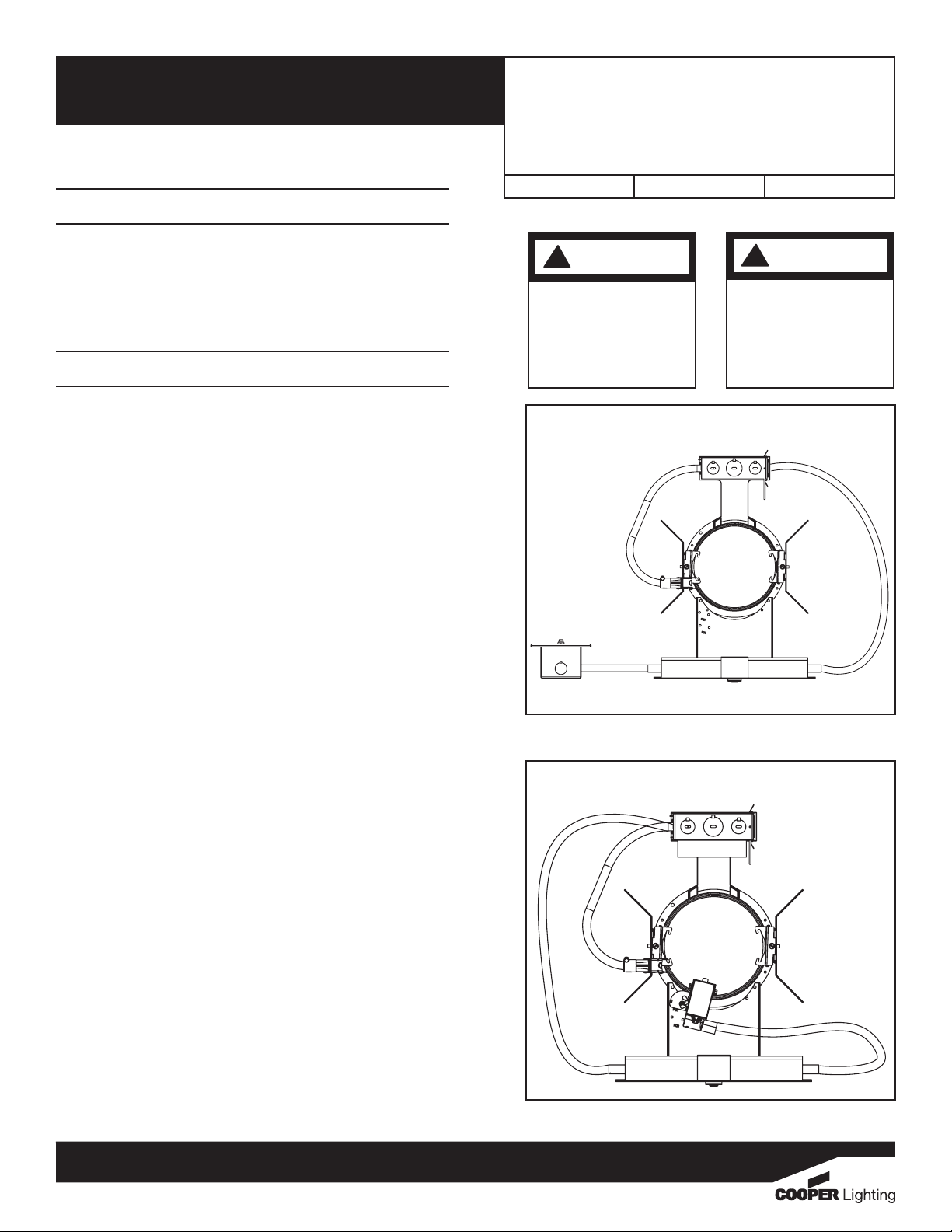
STEP 6: The test switch and indicator light may be provided
for ceiling mounting near the xture in a single gang
switch box (Figure 1) or mounted on the housing in
an adjustable bracket to position directly in a
reector (Figure 2).
STEP 7: When used in insulated ceilings, insulation must be
kept off of the unit and no closer than 3” from the
unit on all sides.
STEP 8: Do not use this equipment for other than the
intended use.
STEP 9: Install only in accordance with National Electric Code
and local regulatory agencies requirements.
STEP 10: Installation and servicing to be performed only by
qualied personnel.
WARNING
!
Risk Of Electrical Shock
Disconnect power at fuse
or circuit breaker before
installing or servicing.
Figure 1
Figure 2
WARNING
!
Risk Of Fire
Do not install insulation
within 3 inches (76 mm) of
any part of the luminaire
xture or in a way that
may entrap heat.
ADP132108
Customer First Center 1121 Highway 74 South Peachtree City, GA 30269 770.486.4800 FAX 770.486.4801
Page 2
®
BLACK 120V
PORTFOLIO
INSTALLATION INSTRUCTIONS
IMPORTANT : READ CAREFULLY BEFORE INSTALLING FIXTURE. RETAIN FOR FUTURE REFERENCE
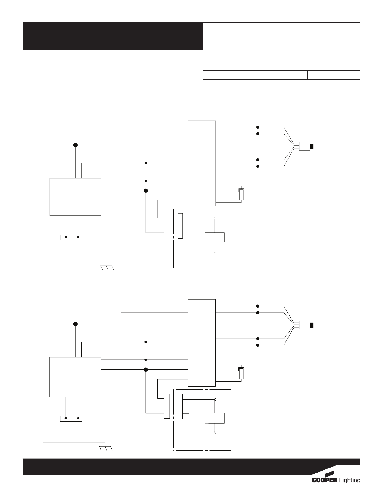
Electrical Wiring Diagrams
LD4A/LD6A Emergency
Commercial Recessed Installation
Instructions
706084INS
4/04/13 page 2
D010TE EMBOD (SEE WEBSITE FOR AVAILABILITY)
WHITE/RED (SWITCHED HOT)
ORANGE/BLACK (UNSWITCHED HOT)
WHITE JUMPER WIRE
(COMMON)
WHITE (INPUT)
TRAILING EDGE
DIMMING OR
0-10V DIMMING DRIVER
PURPLE
0-10V DIMMING OPTION
(FIELD INSTALLATION)
GROUND
BLACK (INPUT)
RED (+)
BLACK (-)
GRAY
WHITE
WHITE/BLACK
BLUE
YELLOW/BLACK
YELLOW
CONNECTOR
D010TR EMBOD (SEE WEBSITE FOR AVAILABILITY)
WHITE/RED (SWITCHED HOT)
ORANGE/BLACK (UNSWITCHED HOT)
WHITE JUMPER WIRE
(COMMON)
WHITE
FLEX A
RED (+)
CONNECTOR
BLACK (-)
MODULE WIRING
DIAGRAM
BLACK 120V
OR
ORANGE 277V
(CAP UNUSED LEAD)
ORANGE/BLACK
VIOLET (+)
BROWN (-)
FLEX B
WHITE
CONVERTER
BODINE EMERGENCY BATTERY PACK
RED
LED
ORANGE 277V
(CAP UNUSED LEAD)
ORANGE/BLACK
CONNECTOR
OR
BLACK
BLACK
ITS
VIOLET
BROWN
BLACK
BLACK
ITS
VIOLET (+)
BROWN (-)
FLEX B
WHITE
RED
LED
WHITE (INPUT)
TRIAC DIMMING @
120VAC OR 0-10V
@120-277VAC
DIMMING DRIVER
GRAY
PURPLE
0-10V DIMMING OPTION
(FIELD INSTALLATION)
GROUND
BLACK (INPUT)
RED (+)
BLUE (-)
WHITE/BLACK
BLUE
YELLOW/BLACK
YELLOW
CONNECTOR
FLEX A
RED (+)
CONNECTOR
BLACK (-)
MODULE WIRING
DIAGRAM
BODINE EMERGENCY BATTERY PACK
Customer First Center 1121 Highway 74 South Peachtree City, GA 30269 770.486.4800 FAX 770.486.4801
CONVERTER
CONNECTOR
VIOLET
BROWN
ADP132108
Page 3

®
BLACK 120V
PORTFOLIO
INSTALLATION INSTRUCTIONS
IMPORTANT : READ CAREFULLY BEFORE INSTALLING FIXTURE. RETAIN FOR FUTURE REFERENCE
Electrical Wiring Diagrams
LD4A/LD6A Emergency
Commercial Recessed Installation
Instructions
706084INS
4/04/13 page 3
DL3 EMBOD (SEE WEBSITE FOR AVAILABILITY)
WHITE/RED (SWITCHED HOT)
ORANGE/BLACK (UNSWITCHED HOT)
WHITE JUMPER WIRE
(COMMON)
GREEN WIRE
WHITE (INPUT)
LUTRON DRIVER
(120-277V)
PURPLE
PURPLE
LUTRON
ECOSYSTEM
DIGITAL
CONTROL
DIMMING
(FIELD
INSTALLATION)
GROUND
ORANGE
3 WIRE
DIMMING
(FIELD
INSTALLATION)
BLACK (INPUT)
RED (+)
BLUE (-)
WHITE/BLACK
YELLOW/BLACK
DLT EMBOD (SEE WEBSITE FOR AVAILABILITY)
WHITE/RED (SWITCHED HOT)
ORANGE/BLACK (UNSWITCHED HOT)
WHITE JUMPER WIRE
(COMMON)
WHITE
BLUE
YELLOW
CONNECTOR
CONNECTOR
WHITE
BLACK 120V
OR
ORANGE 277V
(CAP UNUSED LEAD)
ORANGE/BLACK
VIOLET (+)
FLEX A
BODINE EMERGENCY BATTERY PACK
RED (+)
BLACK (-)
MODULE WIRING
DIAGRAM
BROWN (-)
FLEX B
WHITE
RED
LED
OR
ORANGE 277V
(CAP UNUSED LEAD)
ORANGE/BLACK
CONVERTER
CONNECTOR
BLACK
BLACK
ITS
VIOLET
BROWN
BLACK
BLACK
ITS
VIOLET (+)
BROWN (-)
FLEX B
WHITE
RED
LED
GREEN WIRE
WHITE (INPUT)
LUTRON DRIVER
(120V)
GROUND
BLACK (INPUT)
RED (+)
BLUE (-)
WHITE/BLACK
BLUE
YELLOW/BLACK
YELLOW
CONNECTOR
FLEX A
RED (+)
CONNECTOR
BLACK (-)
MODULE WIRING
DIAGRAM
BODINE EMERGENCY BATTERY PACK
Customer First Center 1121 Highway 74 South Peachtree City, GA 30269 770.486.4800 FAX 770.486.4801
CONVERTER
CONNECTOR
VIOLET
BROWN
ADP132108
Page 4

®
BLACK 120V
PORTFOLIO
INSTALLATION INSTRUCTIONS
IMPORTANT : READ CAREFULLY BEFORE INSTALLING FIXTURE. RETAIN FOR FUTURE REFERENCE
Electrical Wiring Diagrams
LD4A/LD6A Emergency
Commercial Recessed Installation
Instructions
706084INS
4/04/13 page 4
DL5T EMBOD (SEE WEBSITE FOR AVAILABILITY)
WHITE/RED (SWITCHED HOT)
ORANGE/BLACK (UNSWITCHED HOT)
WHITE JUMPER WIRE
(COMMON)
GREEN WIRE
(FIELD INSTALLATION)
WHITE (INPUT)
BLUE~
BROWN~
DRIVER
(120-277V)
DA
-
+
PURPLE
PURPLE
DIMMING LEADS
GROUND
+
-
GROUP 1
BLACK (INPUT)
RED (+)
BLACK (-)
WHITE
WHITE/BLACK
YELLOW/BLACK
YELLOW
CONNECTOR
DE010 EMBOD (SEE WEBSITE FOR AVAILABILITY)
WHITE/RED (SWITCHED HOT)
ORANGE/BLACK (UNSWITCHED HOT)
WHITE JUMPER WIRE
(COMMON)
WHITE
BLUE
CONNECTOR
BLACK 120V
OR
ORANGE 277V
(CAP UNUSED LEAD)
ORANGE/BLACK
VIOLET (+)
FLEX A
BODINE EMERGENCY BATTERY PACK
RED (+)
BLACK (-)
MODULE WIRING
DIAGRAM
BROWN (-)
FLEX B
WHITE
RED
LED
OR
ORANGE 277V
(CAP UNUSED LEAD)
ORANGE/BLACK
CONVERTER
CONNECTOR
BLACK
BLACK
ITS
VIOLET
BROWN
BLACK
BLACK
ITS
VIOLET (+)
BROWN (-)
FLEX B
WHITE
RED
LED
GREEN WIRE
(FIELD INSTALLATION)
WHITE (INPUT)
BLUE~
BROWN~
DRIVER
(120-277V)
0-10V
-
+
PURPLE
GREY
DIMMING LEADS
GROUND
+
-
GROUP 1
BLACK (INPUT)
RED (+)
BLACK (-)
WHITE/BLACK
BLUE
YELLOW/BLACK
YELLOW
CONNECTOR
FLEX A
RED (+)
CONNECTOR
BLACK (-)
MODULE WIRING
DIAGRAM
BODINE EMERGENCY BATTERY PACK
Customer First Center 1121 Highway 74 South Peachtree City, GA 30269 770.486.4800 FAX 770.486.4801
CONVERTER
CONNECTOR
VIOLET
BROWN
ADP132108
Page 5

®
PORTFOLIO
INSTALLATION INSTRUCTIONS
IMPORTANT : READ CAREFULLY BEFORE INSTALLING FIXTURE. RETAIN FOR FUTURE REFERENCE
Electrical Wiring Diagrams
LD4A/LD6A Emergency
Commercial Recessed Installation
Instructions
706084INS
4/04/13 page 5
DMX EMBOD (SEE WEBSITE FOR AVAILABILITY)
WHITE/RED (SWITCHED HOT)
ORANGE/BLACK (UNSWITCHED HOT)
WHITE JUMPER WIRE
(COMMON)
GREEN WIRE
WHITE (INPUT)
BLUE~
DRIVER
(120-277V)
DMX in +
YELLOW
DIMMING LEADS
(FIELD INSTALLATION)
GROUND
BROWN~
DMX in -
ORANGE
GROUP 1
DMX in shield
BROWN
BLACK (INPUT)
RED (+)
+
BLACK (-)
-
WHITE/BLACK
YELLOW/BLACK
WHITE
BLUE
YELLOW
CONNECTOR
CONNECTOR
BLACK 120V
OR
ORANGE 277V
(CAP UNUSED LEAD)
ORANGE/BLACK
VIOLET (+)
FLEX A
BODINE EMERGENCY BATTERY PACK
RED (+)
BLACK (-)
MODULE WIRING
DIAGRAM
BROWN (-)
FLEX B
WHITE
RED
LED
CONVERTER
CONNECTOR
BLACK
BLACK
ITS
VIOLET
BROWN
Customer First Center 1121 Highway 74 South Peachtree City, GA 30269 770.486.4800 FAX 770.486.4801
ADP132108
 Loading...