

Page 1
MS275RD
MS275RDW
ENGLISH
ESPAÑOL
FRANÇAIS
Instruction Manual
Instrucciones
Directives
MS275RD_RDW 825-0133.qxd:RFM181 I.S. 325-1384.qxd 8/28/08 11:18 AM Page 1
Page 2
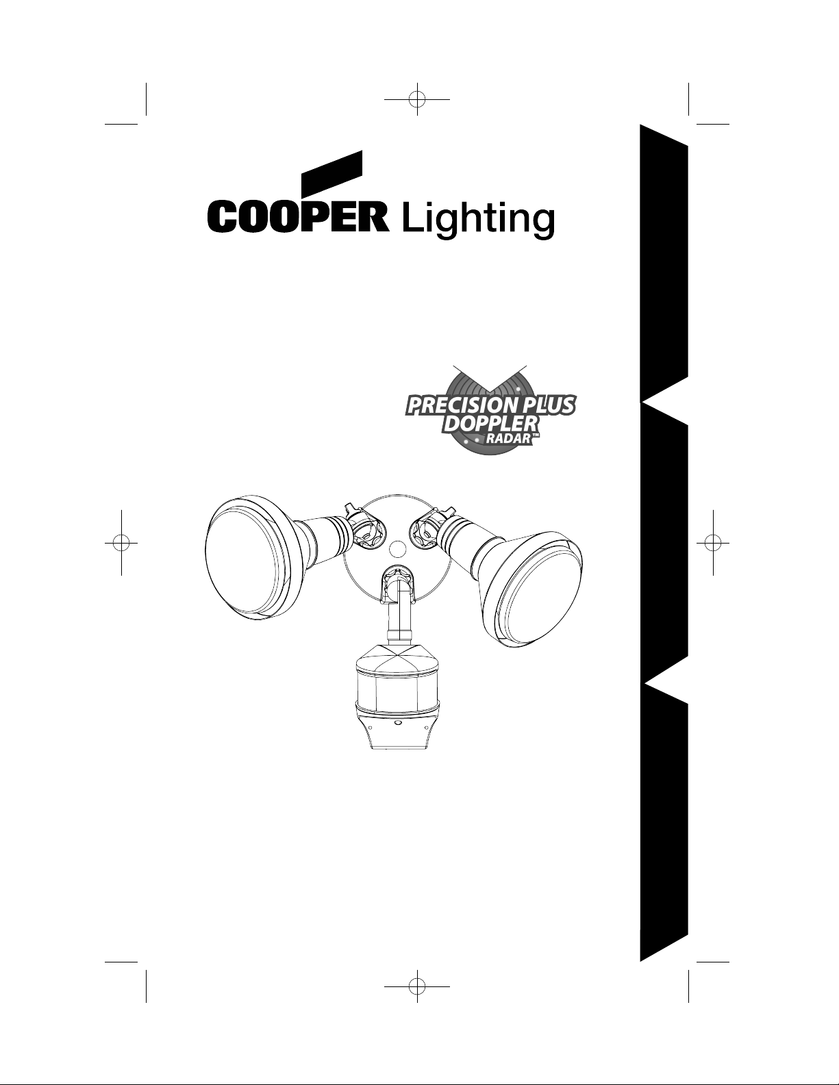
MS275RD (Bronze)
MS275RDW (White)
2
ENGLISH
Congratulations. You have just purchased a Cooper Lighting, LLC motion-
activated floodlight that combines both Precision Plus Doppler Radar™ and PIR
(Passive Infrared) technology. This combination provides the maximum
accuracy and protection for your home and family.
How it works
PIR does a good job of detecting lateral motion across the 270° range of
detection. Precision Plus Doppler Radar™ does an excellent job detecting
motion towards and away from the unit. Both systems combined provide
enhanced accuracy and complete coverage within the detection range. Rest
assured that motion from any direction will trigger your floodlight—even during
hot or cold temperature extremes.
What you need
• Phillips screwdriver
• Outdoor weatherproof silicone caulking
• (2) 150 Watt (MAX) PAR 38 floodlight bulbs (A)
Note: This fixture was designed to work with up to 150 Watt maximum PAR
flood bulbs. For improved energy efficiency, lower wattage PAR or CFL flood
bulbs can be used.
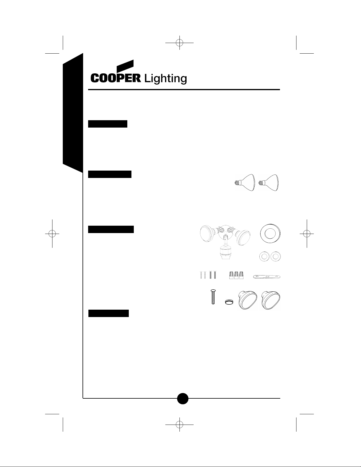
What’s included
• Motion detector and light fixture (B)
• Coverplate gasket (C)
• (2) Lampholder gaskets (D)
• (2) #6 and (2) #8 mounting screws (E)
• (3) Wire nuts (F)
• Mounting bracket (G)
• Center bolt (H)
• Color-matched center hole plug (I)
• (2) Light covers (J)
What to know
PLEASE READ THESE IMPORTANT SAFETY INSTRUCTIONS
• For outdoor use only.
• cULus LISTED for wet locations.
• Fixture must be connected to a 120 Volt, 60 Hz power source. Any other
connection voids warranty.
• Fixture should be mounted to a grounded junction box marked for use in
wet locations.
• Suitable for wall mount or eave mount only. NOT suitable for ground
mount installation.
Call for customer service and/or missing or damaged parts (800-334-6871)
A
I
D
F
H
C
E
J
B
G
MS275RD_RDW 825-0133.qxd:RFM181 I.S. 325-1384.qxd 8/28/08 11:18 AM Page 2
Page 3
Call for customer service and/or missing or damaged parts (800-334-6871)
3
ENGLISH
• Keep away from flammable objects. Do not position fixture
within one inch of any combustible materials.
• The bulb and fixture get extremely hot during use.
• This twin floodlight should be installed by a qualified electrician or by persons
with experience in household wiring. The electrical system, and the method of
electrically connecting this fixture to it, must be in accordance with the
National Electrical Code and local building codes.
• Always replace bulb with the same wattage or lower wattage than marked.
Installing a bulb of a higher wattage could create a fire hazard. Use of a
higher wattage bulb will void the warranty.
• Never touch the bulb with your bare hands, as oil from your skin can cause
premature failure. Always handle the bulb with gloves or a soft cloth.
• Disassembly of your fixture will void the warranty.
• For supply connections, use wire rated at least 90° C.
• In the event of glass breakage, the entire lens cover must be replaced per UL
requirements. Contact Customer Service for ordering assistance.
• This device complies with Part 15 of the FCC Rules. Operation is subject
to the following two conditions: (1) This device may not cause harmful
interference, and (2) this device must accept any interference received,
including interference that may cause undesired operation. Under Part 15 of
the FCC Rules, any changes or modifications to the motion detector described
in this instruction sheet that are not expressly approved by Cooper Lighting,
LLC could void the user’s authority to operate the equipment.
Note: This equipment has been tested and found to comply with the
limits for a Class B digital device, pursuant to Part 15 of the FCC Rules.
These limits are designed to provide reasonable protection against harmful
interference in a residential installation. This equipment generates, uses
and can radiate radio frequency energy and if not installed and used in
accordance with the instructions, may cause harmful interference to radio
communications. However, there is no guarantee that interference will not
occur in a particular installation. If this equipment does cause harmful
interference to radio or television reception, which can be determined by
turning the equipment off and on, the user is encouraged to try to correct
the interference by one or more of the following measures:
• Reorient or relocate the receiving antenna.
• Increase the separation between the equipment and receiver.
• Connect the equipment into an outlet on a circuit different from
that to which the receiver is connected.
• Consult the dealer or an experienced radio/TV technician for help.
WARNING: FCC Regulations state that any unauthorized changes or
modifications to this equipment not expressly approved by the manufacturer could void the user's authorization to operate this equipment.
SAVE THESE INSTRUCTIONS.
For best results
• Install the motion sensor/transmitter 8-12 feet above ground (motion sensor
is less sensitive above 12 feet).
MS275RD_RDW 825-0133.qxd:RFM181 I.S. 325-1384.qxd 8/28/08 11:18 AM Page 3
Page 4

4
ENGLISH
• Locate motion sensor so motion moves laterally or
towards the detection zone (Fig. 1).
• Locate sensor away from heat producing sources to
prevent false triggering. Also, be very careful not to
include objects such as windows, white walls and water in
the detection zone whenever possible.
• Locate sensor away from moving objects such as trees
and street traffic.
• Do not install more than one motion-activated floodlight
on one wall switch.
Mounting your light fixture
Step 1: WARNING: Risk of electric shock.
Disconnect power at fuse or circuit
breaker before installing or servicing.
Note: Junction box must be at least 1-1/2˝ in
depth for proper installation.
Step 2: Line up the holes on the mounting bracket
with the holes on your junction box. Using
either (2) #6 screws or (2) #8 screws
(depending on the size of the holes in
you junction box), attach the mounting
bracket to your junction box (Fig. 2).
Step 3: Thread fixture wires through coverplate gasket.
Step 4: Connect copper colored ground wire (coming
from the fixture coverplate) to the house
ground wire using wire nut provided.
Connect fixture black wire to house black
wire, fixture white wire to house white wire
using wire nuts provided.
Step 5: Attach fixture to the mounting bracket using the center
bolt provided. Insert plastic color-matched plug in
center bolt hole for finished appearance.
Step 6: Apply silicone caulking around edges of
coverplate and in any open holes to provide
a watertight seal from rain and moisture.
Step 7: Install protective lamp covers onto
lampholders by lining up the nipples
on the covers, over the lampholder slots.
Lock into place by twisting covers
counterclockwise (Fig. 3).
Step 8: Insert gaskets into lampholders and screw
bulbs into each lampholder (do not over
tighten bulbs).
Step 9: Turn power on at main fuse/breaker box.
Note: Fixture can be wall or eave mounted (Fig. 4).
Round Octagonal
Your fixture mounts
to the following standard
junction boxes:
Call for customer service and/or missing or damaged parts (800-334-6871)
1-1/2˝
1-1/2˝
Fig. 2
Fig. 3
(wall mount)
(eave mount)
Fig. 4
Fig. 1
MS275RD_RDW 825-0133.qxd:RFM181 I.S. 325-1384.qxd 8/28/08 11:19 AM Page 4
Page 5

5
ENGLISH
Aiming the light
Loosen the knob on the side of the lamp holder. Tilt lamp holder up or
down to desired position then retighten knob.
WARNING: Deviation from the assembly instructions may result in
a risk of electric shock.
How to operate your fixture
Step 1: Turn the arrow on the MODE knob to the
TEST for test mode (Fig. 5).
Step 2: Turn the arrow on the SENSITIVITY knob
to a middle point between “+” and “-”.
Step 3: Turn on the power to the fixture. Allow fixture to warm up
approximately 90 seconds before testing. (Lights may or may not
come on during warm-up period; this is normal.)
Step 4: Aim sensor toward the general direction that motion will be coming
from. Maintain at least 1˝ of clearance between sensor head and
lamps. Always position the sensor head with control switches facing
toward the ground.
Note: (Sensor Head Placement) For optimum detection, you may have to
experiment with aiming and settings. Each location will be different and your
terrain may affect the angle your sensor needs. Adjusting the angle will change
your area of detection. Here are some general guidelines to help with setup:
• 8´-12´ above the ground is a good range for
the placement of your fixture.
• For an 8´ mounting height, placing the sensor
at a 10° angle below horizontal should work
well for most locations (Fig. 6).
• If the fixture is mounted higher, the angle of
the sensor below horizontal should increase.
• If the fixture is mounted lower than 8´, the
angle of the sensor below horizontal should
decrease but never be parallel to horizontal.
Step 5: Walk through the detection zone at the
farthest distance you want your detector to
detect motion.
Step 6: Adjust the SENSITIVITY knob until you get
desired results. For more range, aim sensor
slightly upward. For less range, aim sensor head
slightly downward. Lights will turn off 2 seconds after motion stops.
Step 7: Adjust the MODE knob to a time selection from 1m-12m,
depending on how many minutes you want the fixture to stay on
after motion is detected. At dusk, the photo control will activate
your fixture to operate according to the settings chosen.
Note: Decreasing the SENSITIVITY will decrease the distance the unit
can detect.
Call for customer service and/or missing or damaged parts (800-334-6871)
Fig. 5
Fig. 6
10°
0°
Incorrect
Correct
MS275RD_RDW 825-0133.qxd:RFM181 I.S. 325-1384.qxd 8/28/08 11:19 AM Page 5
Page 6

6
ENGLISH
Selecting your mode of operation
Call for customer service and/or missing or damaged parts (800-334-6871)
Test Setting
Light should turn ON with
motion both day and
night. Lights should
turn OFF after 2 seconds.
MODE knob arrow
points to TEST
Wall Switch Setting
(connected to fixture)
Keep wall switch
in ON position.
Motion-Activated
Setting
Lights should turn ON with
motion only at night and
should turn OFF after
1-12 min. of no motion
MODE knob arrow
points to a time selection
within the 1m-12m
time range
Keep wall switch in
ON position.
Keep the power to
the fixture ON.
Return to
Motion-Activated
Setting from any of
the above settings
MODE knob arrow
points to a time selection
within the 1m-12m
time range
Turn the power OFF
for at least 90 seconds
and then back ON.
Mode of
Operation:
MODE Knob
Adjustment:
How to Set
Power Switch:
Standard Floodlight
Mode
(activated only at night)
Lights should stay on from
dusk to dawn and then reset
to motion-activated
setting at the next dawn.
MODE knob arrow
points to a time selection
within the 1m-12m
time range
Turn power OFF
for 5 seconds and then
back ON.
MS275RD_RDW 825-0133.qxd:RFM181 I.S. 325-1384.qxd 8/28/08 11:19 AM Page 6
Page 7

7
ENGLISH
Call for customer service and/or missing or damaged parts (800-334-6871)
What to do if . . .
Is there motion in the detection zone?
• Make sure the sensor is not picking up moving objects
such as trees, traffic, etc.
TEST FOR YOURSELF
• Cover the sensor lens with cardboard to prevent
sensor from detecting motion. If the lights stay off,
something in the detection zone is triggering the sensor.
• If this is the case, reduce the sensitivity.
• Reposition motion sensor.
*If the lights stay on with sensor lens covered,
contact customer service.
Is the unit in the motion-activated setting?
• Make sure MODE knob is set between 1m-12m.
Is there motion in the detection zone?
• Make sure the sensor is not picking up moving objects
such as trees, traffic, etc.
• If this is the case, reduce the sensitivity.
• Reposition motion sensor.
If there is no motion, then the unit may be in the override mode.
• Turn the light switch to the OFF position for 90 seconds,
and then back to the ON position. This will send the unit
back into the motion-activated setting.
*If the lights continue to stay on, contact customer
service.
Is the unit in the AUTO mode?
• Make sure the unit is set between 1m-12m (AUTO mode).
The light given off from the unit’s own lamp(s) is affecting the
motion sensor.
• Re-aim lamp(s).
• Reposition motion sensor.
Is the switch on the bottom of the motion sensor in the test
mode?
• Reposition MODE knob off of TEST to a time selection
(1m-12m).
• Move the switch off of TEST.
Is the motion detector shadowed?
• Reposition motion sensor.
OUTDOOR LIGHTS COME ON
FOR NO APPARENT REASON
AT NIGHT
LIGHTS STAY ON AT NIGHT
AND DO NOT TURN OFF
LIGHTS CONTINUOUSLY BLINK
ON AND OFF AT NIGHT
LIGHTS ARE ON
DURING THE DAY
Is there power to the fixture?
• Check to see that the circuit breaker has not been tripped.
• Be sure the wall switch is in the ON position.
• Be sure that the bulbs are not burned out or broken.
Is the surrounding external ambient light too bright? (If so, the
unit may think it’s daytime.)
• Re-aim the head.
• Relocate or reposition the unit away from the light.
TURN OFF POWER BEFORE CONTINUING.
Is the wiring to the fixture loose?
• Check wiring, and reconnect if necessary using wire nuts
provided.
OUTDOOR LIGHTS DO NOT
COME ON WITH MOTION AT
NIGHT
MS275RD_RDW 825-0133.qxd:RFM181 I.S. 325-1384.qxd 8/28/08 11:19 AM Page 7
Page 8

8
ENGLISH
Two-year limited warranty
Cooper Lighting, LLC (“the Company”) warrants this product (“the product”)
against defects in material or workmanship for a period of two years from date
of original purchase, and agrees to repair or, at the Company’s option, replace
a defective product without charge for either replacement parts or labor during
such time. This does not include labor to remove or install fixtures.
This warranty is extended only to the original purchaser of the product.
A purchasers receipt or other proof of date of original purchase acceptable to
the Company is required before warranty performance shall be rendered.
This warranty only covers product failure due to defects in materials or
workmanship which occurs in normal use. It does not cover the bulb or failure
of the product caused by accident, misuse, abuse, lack of reasonable care,
alteration, or faulty installation, subjecting the product to any but the specified
electrical service or any other failure not resulting from defects in materials or
workmanship. Damage to the product caused by separately purchased,
non-Company brand replacement bulbs and corrosion or discoloration of brass
components are not covered by this warranty.
There are no express warranties except as described above.
THE COMPANY SHALL NOT BE LIABLE FOR INCIDENTAL, SPECIAL OR
CONSEQUENTIAL DAMAGES RESULTING FROM THE USE OF THE
PRODUCT OR ARISING OUT OF ANY BREACH OF THIS WARRANTY. ALL
IMPLIED WARRANTIES, IF ANY, INCLUDING IMPLIED WARRANTIES OF
MERCHANTABILITY AND FITNESS FOR A PARTICULAR PURPOSE, ARE
LIMITED IN DURATION TO THE DURATION OF THIS EXPRESS WARRANTY.
Some states do not allow the exclusion or limitation of incidental or
consequential damages, or limitations on how long an implied warranty lasts, so
the above exclusions or limitations may not apply to you.
No other warranty, written or verbal, is authorized by the Company. This
warranty gives you specific legal rights, and you may also have other rights
which vary from state to state.
To obtain warranty service, please write to Cooper Lighting, LLC, 1121 Highway
74 South, Peachtree City, GA 30269. Enclose product model number and
problems you are experiencing, along with your address and telephone
number. You will then be contacted with a solution, or a Return Goods
Authorization number and full instructions for returning the product. All returned
products must be accompanied by a Return Goods Authorization Number
issued by the Company and must be returned freight prepaid. Any product
received without a Return Goods Authorization Number from the
Company will be refused.
Cooper Lighting, LLC is not responsible for merchandise damaged in transit.
Repaired or replaced products shall be subject to the terms of this warranty and
are inspected when packed. Evident or concealed damage that is made in transit should be reported at once to the carrier making the delivery and a claim
filed with them.
Call for customer service and/or missing or damaged parts (800-334-6871)
MS275RD_RDW 825-0133.qxd:RFM181 I.S. 325-1384.qxd 8/28/08 11:19 AM Page 8
Page 9

9
ENGLISH
Customer First Center
1121 Highway 74 South, Peachtree City, GA 30269
www.cooperlighting.com
© 2008 Cooper Lighting, LLC
Reproductions of this document without prior written approval of Cooper Lighting, LLC
are strictly prohibited.
Call for customer service and/or missing or damaged parts (800-334-6871)
Printed in China
MS275RD_RDW 825-0133.qxd:RFM181 I.S. 325-1384.qxd 8/28/08 11:19 AM Page 9
 Loading...