

Page 1

Manufacturer: Cooper Lighting, LLC
Certification Exhibit
FCC ID: NCG-MS180D
FCC Rule Part: 15.245
ACS Project Number: 11-0249
Manual
5015 B.U. Bowman Drive Buford, GA 30518 USA Voice: 770-831-8048 Fax: 770-831-8598
Page 2
Questions?/¿Preguntas? 1-800-334-6871 ConsumerProducts@cooperlighting.com
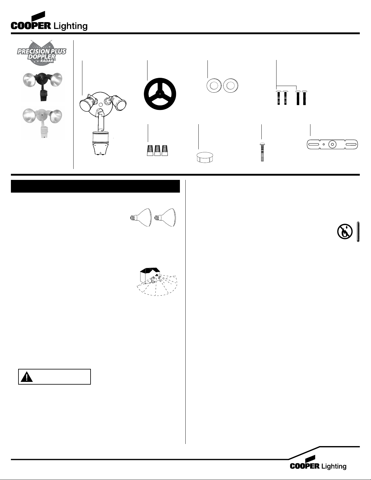
PACKAGING CONTENTS/ CONTENIDO DEL PAQUETE
A. Motion detector
and light fixture
Detector de
movimiento y
artefacto de luz
B. Coverplate gasket
Junta de la placa
de cubierta
C. (2) Lampholder gaskets
(2) Juntas obturadoras
del receptáculo
Instruction Manual/Instrucciones
D. (2) #6 and (2) #8 mounting screws
(use the size that fits your junction box)
(2) Tornillos #6 y (2) tornillos #8 de montaje
(utilice el tamaño que mejor se adecue a
su caja de conexión)
E. (3) Wire nuts
(3) Conectores
de cable
CMS185D (Bronze)
CMS185DW (White)
ENGLISH
ITEMS REQUIRED
(Purchase separately)
• Phillips screwdriver
• Outdoor weatherproof silicone caulking
• (2) 100 watt (MAX) PAR 38 floodlight bulbs
NOTE: This fixture was designed to work with up to 150 watt maximum PAR halogen flood
bulbs. For improved energy efficiency, lower wattage PAR halogen flood bulbs may be used.
Compact Fluorescent (CFL) bulbs contain electronics which may interfere with the motion
sensing function of your fixture and are not recommended. To meet ENERGY STAR
requirements, maximum total lamp wattage can not exceed 250 watts.
HOW IT WORKS
PIR does a good job of detecting lateral motion across the 180°
range of detection. Precision Plus Doppler Radar™ does an
excellent job detecting motion towards and away from the unit.
Both systems combined provide enhanced accuracy and complete
coverage within the detection range. Motion from any direction will
trigger your floodlight—even during hot or cold temperature extremes.
IMPORTANT SAFETY INSTRUCTIONS
When using product, basic precautions should always be followed, including the following:
• Read and follow these instructions.
• Heed all warnings, including below warnings AND those included on product.
• Save these instructions and warnings.
• For outdoor use only.
• cETLus LISTED for wet location.
• Suitable for wall mount or eave mount only. NOT suitable for ground mount installation.
• Disassembling your fixture will void the warranty.
• Your fixture is prewired and preassembled for easy installation.
®
Up to
70 feet
180 degrees
WARNING
• Bulb gets HOT quickly!
• The bulb and fixture get extremely hot during use. Disconnect power and allow fixture
to cool before changing bulb or handling fixture.
• Fixture should be installed by persons with experience in household wiring or by a
qualified electrician. The electrical system, and the method of electrically connecting
the fixture to it, must be in accordance with the National Electrical Code and local
building codes.
• Always replace bulb with the same wattage or lower wattage than marked. Installing
a bulb of a higher wattage could create a fire hazard. Use of a higher wattage bulb will
void the warranty. (Maximum 150 watt PAR halogen bulb.)
F. Color-matched
center hole plug
Tapón para agujero
central de color
coincidente
G. Mounting plate
screw
Tornillo para la
placa de montaje
H. Mounting bracket
Soporte de montaje
CAUTION
• Connect fixture to a 120 volt, 60 Hz power source. Any other connection voids
the warranty.
• Fixture must be mounted to a grounded recessed junction box marked for use
in wet locations.
• Suitable for wall mount or eave mount only. NOT suitable for ground mount installation.
• Do not allow sensor head to touch light housing – maintain at least 1 inch space
between fixture and sensor.
• Keep away from flammable objects. Do not position fixture within
2 inches of any combustible materials.
• For proper operation and protection against damage, the motion
sensor head adjustment knobs must be facing the ground.
• MINIMUM 90° C SUPPLY CONDUCTORS.
• Do not use this apparatus near water.
• Clean only with a dry cloth.
• Do not block any ventilation openings. Install in accordance with the manufacturer’s
instructions.
• Do not install near any heat sources such as radiators, heat registers, stoves or other
apparatus (including amplifiers) that produce heat.
• Only use attachments/accessories specified by the manufacturer.
• This device complies with Part 15 of the FCC Rules. Operation is subject to the
following two conditions: (1) This device may not cause harmful interference, and
(2) this device must accept any interference received, including interference that
may cause undesired operation. Under Part 15 of the FCC Rules, any changes or
modifications to the motion detector described in this instruction sheet that are
not expressly approved by Cooper Lighting, LLC could void the user’s authority to
operate the equipment.
NOTE: This equipment has been tested and found to comply with the limits for
a Class B digital device, pursuant to Part 15 of the FCC Rules. These limits are
designed to provide reasonable protection against harmful interference in a
residential installation. This equipment generates, uses and can radiate radio
frequency energy and if not installed and used in accordance with the instructions,
may cause harmful interference to radio communications. However, there is no
guarantee that interference will not occur in a particular installation. If this equipment
does cause harmful interference to radio or television reception, which can be
determined by turning the equipment off and on, the user is encouraged to try to
correct the interference by one or more of the following measures:
- Reorient or relocate the receiving antenna.
- Increase the separation between the equipment and receiver.
- Connect the equipment into an outlet on a circuit different from that to which the
receiver is connected.
- Consult the dealer or an experienced radio/TV technician for help.
WARNING: FCC Regulations state that any unauthorized changes or
modifications to this equipment not expressly approved by the manufacturer
could void the user’s authorization to operate this equipment.
1
Page 3

• Under Industry Canada regulations, this radio transmitter may only operate using
an antenna of a type and maximum (or lesser) gain approved for the transmitter by
Industry Canada. To reduce potential radio interference to other users, the antenna
type and its gain should be so chosen that the equivalent isotropically radiated power
(e.i.r.p.) is not more than that necessary for successful communication.
• This device complies with Industry Canada license-exempt RSS standard(s). Operation
is subject to the following two conditions: (1) this device may not cause interference,
and (2) this device must accept any interference, including interference that may
cause undesired operation of the device.
FOR BEST RESULTS
• Install the motion sensor/transmitter 8-12 feet
above the ground. (Motion sensor is less sensitive
above 12 feet.)
• Locate motion sensor so motion moves laterally or
towards the detection zone (Fig. 1).
• Locate sensor away from heat producing sources to
prevent false triggering. Also be very careful not to
include objects such as windows, white walls and
water in the detection zone.
• Locate sensor away from moving objects such as
trees, large shrubs and street traffic.
• Do not install more than one motion activated
floodlight on one wall switch.
MOUNTING AND WIRING YOUR FIXTURE
NOTE: Universal coverplate mounts to recessed or
surface mounted standard junction boxes (Fig. 2).
Junction box must be at least 1-1/2 inches in depth for
proper installation for recessed mount application.
NOTE: For best performance when installing more than
one Precision Plus Doppler Radar™ fixture:
• Two or more units mounted side by side (facing the
same direction) should be at least 17 feet apart.
• Two units facing each other should be mounted at
least 100 feet apart.
• Fixture can be wall or eave mounted (Fig. 3).
WARNING: Risk of electric shock. Disconnect
power at fuse or circuit breaker before installing
or servicing.
1. Turn off the power at the main fuse/breaker box.
2. Line up the holes on the mounting bracket (H) with
the holes on your junction box. Using either (2) #6
screws or (2) #8 screws (D) (depending on size of
the holes in your junction box), attach the mounting
bracket (H) to your junction box (Fig. 4).
3. Thread fixture wires through coverplate gasket (B)
and position gasket (B) on the coverplate.
4. Connect the black wire from the fixture (A) to the
black house supply wire and the white wire from
the fixture (A) to the white supply wire using the
wire nuts (E) provided. Attach the ground wire
coming from your house to the copper ground wire
from the fixture (A) using wire nut (E) provided. If no
house ground wire is available, attach the copper
ground wire from the fixture (A) to the junction box
if it is metal and grounded. If junction box is not
metal and no house ground wire is available, an
alternative ground source must be used for safe
operation (Fig. 5).
5. Attach fixture (A) to the mounting bracket (H) using
the center bolt (G) provided. Be sure no loose wires
remain sticking out from underneath the coverplate.
Insert plastic color-matched plug (F) in center bolt
hole for finished appearance (Fig. 6).
6. Apply silicone caulk around the edges of the
coverplate to provide a watertight seal from rain
and moisture.
7. Insert lampholder gaskets (C) into lampholder
assembly, tightly against lampholder, and screw
bulbs into each lampholder (Fig. 7). (Do not
overtighten bulbs.)
8. Turn on power at main fuse/breaker box.
AIMING THE LIGHT
Loosen the knob on the side of the lampholder.
Tilt lampholder up or down to desired position, then
retighten knob.
WARNING: Deviation from the assembly
instructions may result in a risk of electric shock.
Wall mount Eave mount
Fig. 1
Fig. 2
1-1/2 in. 1-1/2 in.
Round
Octagonal
Fig. 3
Fig. 4
D
D
Fig. 5
H
E
E
B
E
Fig. 6
A
G
Fig. 7
C
OPERATING YOUR FIXTURE
1. Turn the arrow on the MODE knob to “TEST” for test
mode (Fig. 8).
2. Turn the arrow on the SENSITIVITY knob to a middle
point between “+” and “-”.
3. Turn on the power to the fixture. Allow fixture to
warm up approximately 90 seconds before testing.
(Lights may or may not come on during warm-up
period; this is normal.)
4. Aim sensor toward the general direction that motion
will be coming from. Maintain at least 1˝ of
clearance between sensor head and lamps. Always
position the sensor head with control switches
facing toward the ground.
NOTE: (Sensor Head Placement) For optimum
detection, you may have to experiment with aiming and
settings. Each location will be different and your terrain
may affect the angle your sensor needs. Adjusting the
angle will change your area of detection. Here are some
general guidelines to help with setup:
• 8´-12´ above the ground is a good range for the
placement of your fixture.
• For an 8´ mounting height, placing the sensor at a
5° angle below horizontal should work well for
most locations (Fig. 9).
• If the fixture is mounted higher, the angle of the
sensor below horizontal should increase.
5. Walk through the detection zone at the farthest
distance you want your detector to detect motion.
6. Adjust the SENSITIVITY knob until you get desired
results. For more range, aim sensor slightly upward.
For less range, aim sensor head slightly downward.
Lights will turn OFF 4 seconds after motion stops.
7. Adjust the “Auto” MODE knob to a time selection from
1m-12m, depending on how many minutes you want
the fixture to stay on after motion is detected. At dusk,
the photo control will activate your fixture to operate
according to the settings chosen.
NOTE: Decreasing the SENSITIVITY will decrease the
distance the unit can detect.
NOTE: During daylight hours, the red LED indicator light
will flash when motion is detected. This is normal.
ENERGY STAR
®
ENERGY STAR® is sponsored by the U.S.
Environmental Protection Agency & U.S.
Department of Energy.
H
Visit www.energystar.gov to learn more.
To meet ENERGY STAR® requirements, the photosensor control knob must be in the
“Auto” mode to prevent operation during full daylight. Maximum total lamp wattage can not
exceed 250 watts.
Fig. 8
Fig. 9
A
5°
SELECTING YOUR DESIRED FEATURE
Mode of MODE Knob How to Set
Operation Adjustment Power Switch
A
F
C
Test Setting
Lights should turn ON with
motion both day and night.
Lights should turn OFF
after 4 seconds.
Motion Activated Setting “Auto”
Lights should turn ON with
motion only at night and
should turn OFF after
1-12 min. of no motion.
Dusk-to-Dawn Setting
(activated only at night)
Lights should stay ON from
dusk to dawn and then reset
to motion activated
setting after 6 hours.
Return to
Motion Activated Setting
from any of
the above settings.
MODE knob arrow
points to TEST.
“Auto” MODE knob arrow
points to a time
selection within the
1m-12m time range.
MODE knob arrow
points to a time selection
within the 1m-12m
time range.
“Auto” MODE knob arrow
points to a time selection
within the 1m-12m
time range.
Wall Switch Setting
(connected to fixture)
Keep wall switch
in ON position.
Keep wall switch in
ON position.
Keep the power
to the fixture ON.
Turn the power
OFF-ON-OFF-ON
within 3 seconds; light will
go into override mode.
Turn the power OFF
for at least 90 seconds
and then back ON.
2
Page 4

TROUBLESHOOTING
Problem Cause / Solution
Light does not
come on with
motion at night.
Light comes on
for no apparent
reason at night.
Light stays on at
night and does
not turn off.
Light continuously
blinks on and off
at night.
Light is on
during the day.
Red LED Indicator
Light Comes ON
And OFF During
Daylight Hours
No power to the fixture.
• Check if circuit breaker tripped.
• Confirm wall switch is ON.
Bulb is faulty.
• Replace bulb.
Surrounding external ambient light is too bright. (If so, the unit may
think it is daytime.)
• Re-aim the head.
• Relocate or reposition the unit away from the light.
TURN OFF POWER BEFORE CONTINUING
Wiring to the unit is loose.
• Check wiring, and reconnect if necessary using wire
nuts (E) provided.
There is motion in the detection zone.
• Make sure the sensor is not picking up moving objects such as
trees, traffic, etc.
TEST FOR YOURSELF:
• Cover the sensor lens with cardboard to prevent sensor from
detecting motion. If the light stays off, something in the detection
zone is triggering the sensor.
• If this is the case, reduce the sensitivity.
• Reposition the sensor.
* If the light stays on with the sensor lens covered, contact
customer service.
Unit is in the motion activated setting.
• Make sure “Auto” MODE knob is set between 1m-12m.
There is motion in the detection zone.
• Make sure the sensor is not picking up moving objects such as
trees, traffic, etc.
• Reduce the sensitivity.
• Reposition the sensor.
Unit is in override mode (if there is no motion).
• Turn the light switch to the OFF position for 90 seconds, and then
turn back to the ON postion. This will send the unit back into the
motion activated setting “Auto”.
* If the light stays on with the sensor lens covered, contact
customer service.
Unit is in the “Auto” mode.
• Make sure the unit is set between 1m-12m (“Auto” mode).
The light given from the unit’s own lamp is affecting the
motion sensor.
• Re-aim the lamp.
• Reposition motion sensor.
Make sure knob is not positioned between TEST and 1m.
• Reposition knob closer to selected function, either TEST, or 1m.
The controls on the bottom of the motion sensor are in the test mode.
• Reposition MODE knob off of TEST to a time selection (1m-12m).
The motion detector is shadowed.
• Reposition motion sensor.
During daylight hours, the red LED indicator will flash when motion
is detected. This is normal.
LIMITATION OF LIABILITY:
IN NO EVENT SHALL COOPER LIGHTING BE LIABLE FOR SPECIAL, INDIRECT, INCIDENTAL, OR
CONSEQUENTIAL DAMAGES (REGARDLESS OF THE FORM OF ACTION, WHETHER IN CONTRACT,
STRICT LIABILITY, OR IN TORT INCLUDING NEGLIGENCE), NOR FOR LOST PROFITS; NOR SHALL
THE LIABILITY OF COOPER LIGHTING FOR ANY CLAIMS OR DAMAGE ARISING OUT OF OR
CONNECTED WITH THESE TERMS OR THE MANUFACTURE, SALE, DELIVERY, USE, MAINTENANCE,
REPAIR OR MODIFICATION OF COOPER LIGHTING PRODUCTS, OR SUPPLY OF ANY REPLACEMENT
PARTS THEREFORE, EXCEED THE PURCHASE PRICE OF COOPER LIGHTING PRODUCTS GIVING RISE
TO A CLAIM. NO LABOR CHARGES WILL BE ACCEPTED TO REMOVE OR INSTALL FIXTURES.
To obtain warranty service, please contact Cooper Lighting, LLC, at 1-800-334-6871, press
option 2 for Customer Service, or via e-mail ConsumerProducts@cooperlighting.com and
include the following information:
• Name, address and telephone number
• Date and place of purchase
• Catalog and quantity purchase
• Detailed description of problem
All returned products must be accompanied by a Return Goods Authorization Number issued
by the Company and must be returned freight prepaid. Any product received without a Return
Goods Authorization Number from the Company will be refused.
Cooper Lighting, LLC is not responsible for merchandise damaged in transit. Repaired or
replaced products shall be subject to the terms of this warranty and are inspected when
packed. Evident or concealed damage that is made in transit should be reported at once to
the carrier making the delivery and a claim filed with them.
Reproductions of this document without prior written approval of Cooper Lighting, LLC are strictly prohibited.
For assistance, call 1-800-334-6871 or e-mail us at ConsumerProducts@cooperlighting.com
Printed in China
3-YEAR LIMITED WARRANTY
THE FOLLOWING WARRANTY IS EXCLUSIVE AND IN LIEU OF ALL OTHER WARRANTIES,
WHETHER EXPRESS, IMPLIED OR STATUTORY INCLUDING, BUT NOT LIMITED TO, ANY
WARRANTY OF MERCHANTABILITY OR FITNESS FOR ANY PARTICULAR PURPOSE.
Cooper Lighting, LLC (“Cooper Lighting”) warrants to customers that, for a period of three
years from the date of purchase, Cooper Lighting’s products will be free from defects in
materials and workmanship. The obligation of Cooper Lighting under this warranty is expressly
limited to the provision of replacement products. This warranty is extended only to the original
purchaser of the product. A purchaser’s receipt or other proof of date of original purchase
acceptable to Cooper Lighting. This is required before warranty performance shall be rendered.
This warranty does not apply to Cooper Lighting products that have been altered or repaired
or that have been subjected to neglect, abuse, misuse or accident (including shipping damages).
This warranty does not apply to products not manufactured by Cooper Lighting which have been
supplied, installed, and/or used in conjunction with Cooper Lighting products. Damage to the
product caused by replacement bulbs or corrosion or discoloration of brass components are
not covered by this warranty.
3
 Loading...