

Page 1
Catalog #
Project
Comments
Prepared by
Type
Date
SPECIFICATION FEATURES
04/04/2007 9:10:39 AM
Consult your representative for additional options and finishes.
Specifications and Dimensions subject to change without notice.
ADC041674
LAMP CONFIGURATIONS
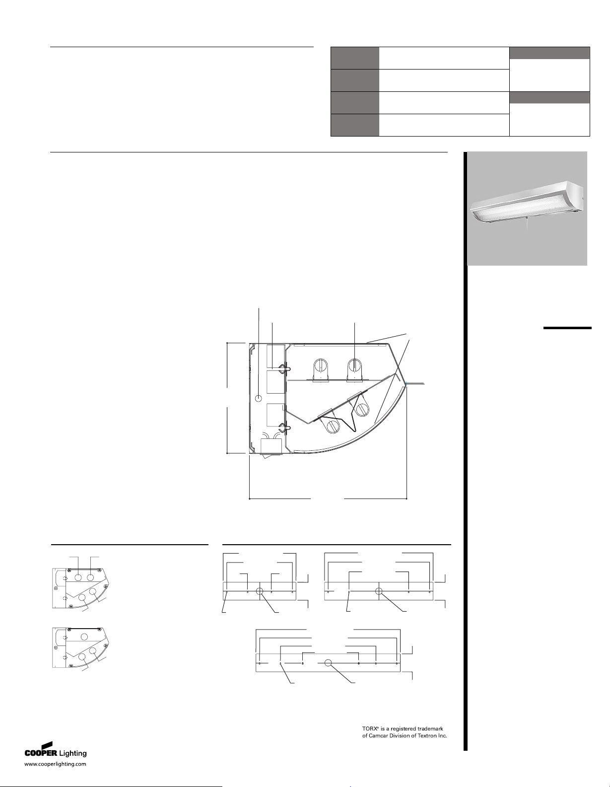
MOUNTING DIMENSIONS
DESCRIPTION
Fail-Safe's MPWA series combines a multi-function, wall mounted luminaire
with the architectural styling of today's healthcare environment. Through
innovative features, the MPWA accommodates multiple applications
throughout the healthcare environment while offering an appealing and
highly styled design for all architectural tastes. The MPWA luminaire has
been designed with the patient and healthcare professional in mind. The
MPWA is separated into two compartments: up light for general ambient
room lighting and down light for reading/direct task lighting to accommo-
date the needs of the patient or healthcare professional. UL Listed.
Application
The MPWA is designed for use in
healthcare environments,
specifically for use in patient
rooms over beds to facilitate all of
the tasks required by the patient
and medical staff. Its exceptional
aesthetics make it ideal for other
applications such as over vanities,
examination areas, rest rooms,
hallways and offices.
A ... Lens
Up light: .125" thick, prismatic K12
pattern, acrylic lens is standard
(prisms on the inside for ease of
cleaning). Down light: .125" thick,
contoured drape formed, prismatic
K12 pattern, acrylic lens is
standard (prisms inside).
B ... Fasteners
Nickel-plated thumbscrews are
standard (requires no tools to
remove lens assembly).
C ... Construction
Outer housing is 18 gauge,
die-formed, cold rolled steel with
seam-welded ends. Back pan
housing is 20 gauge, die formed
cold-rolled steel. Power tray and
reflector are 20 gauge cold rolled
steel.
D ... Lamps
T8 Linear Fluorescent
T5 HO Linear Fluorescent
E ... Ballast Options
T8 Electronic Instant Start
T5 Electronic Programmed Start
T8 Magnetic-HPF
Finish
High gloss white polyester powder
coat finish is standard on exterior
housing. A multistage cleaning and
painting process is utilized. Interior
reflector is high reflectance white,
minimum reflectance 92%. Custom
colors are available.
Labels
UL/cUL Listed for Damp Locations
MPWA
51W - 216W
Fluorescent
ARCHITECTURAL
HEALTHCARE
WALL MOUNTED
LUMINAIRE
6“
[153mm]
8 9/16”
[217mm]
B
E
D
A
C
EN ER GY D AT A
Input Watts:
T5H0 Fluorescent Lamps
Electronic Ballasts*
(3) 24W T5 HO Lamps: 79W
(4) 24W T5 HO Lamps: 104W
(3) 39W T5 HO Lamps: 127W
(4) 39W T5 HO Lamps: 1
74W
(3) 54W T5 HO Lamps: 182W
(4) 54W T5 HO Lamps: 240W
*Energy Data calculated using
3 ballasts per each lamp
configuration. (Programmed start,
normal light output, average ballast
factor 0.95 to 1.1)
T8 Fluorescent Lamps
Electronic Ballasts*
(3) 17W T8 Lamps: 54W
(4) 17W T8 Lamps: 68W
(3) 25W T8 Lamps: 7
4W
(4) 25W T8 Lamps: 94W
(3) 32W T8 Lamps: 90W
(4) 32W T8 Lamps: 116W
*Energy Data calculated using
3 ballasts per each lamp
configuration. (Instant start, normal
light output, average ballast factor
0.9 to 1.0)
1 7/8”
[47MM]
1 7/8”
[47MM]
1 7/8”
[47MM]
24 3/8” [620mm]
22” [559mm]
8“ [203mm]
3/16 X 11/16”
[4.8 X 17.5mm]
Keyhold Mtg. Holes
2 1/4”
[57mm] Dia.
Access Hole
6“
[153mm]
36 3/8” [925mm]
34” [864mm]
20” [508mm]
6“
[153mm]
2 1/4”
[57mm] Dia.
Access Hole
6“
[153mm]
2 1/4”
[57mm] Dia.
Access Hole
3/16 X 11/16”
[4.8 X 17.5mm]
Keyhold Mtg. Holes
3/16 X 11/16”
[4.8 X 17.5mm]
Keyhold Mtg. Holes
48 3/8” [1229mm]
46” [1168mm]
32” [813mm]
16” [406mm]
FAIL - SAFE
®
Page 2

Specifications and Dimensions subject to change without notice.
MPWA
F e a t u r e s , C a t a l o g L o g i c
a n d O p t i o n s
The MPWA features a reflector
system in the lower optical
compartment that facilitates two
tasks-reading and patient
examination.
The MPWA is used for obtaining
maximum efficiency while
providing cut off and glare control
to the remaining of the room’s
surroundings. With the push of a
switch, the upper lamp of the
lower compartment can be
energized to aid in evaluation of
the patient. The reflector works
with this lamp by providing
maximum output and control of
light over the patient’s torso for
examination or any other tasks
that may be necessary. The
effectiveness of this lamp/optical
system is maximized by its
flexibility in utilizing these two
lamps in conjunction or
separately.
B a l l a s t s
Fixtures are supplied standard
with electronic ballasts.
Magnetic, energy saving ballasts
are available with T8 lamps only
(LEOC8). An optional radio
interference filter (RIF) is
commonly used with magnetic
ballasts to reduce radio
interference with sensitive
equipment.
C i r c u i t r y
All individual input circuits will be
supplied with a quick disconnect
module (QDM) to facilitate ease of
maintenance and installation.
GCO (grounded convenience
outlet) and FNL (fluorescent night
light) options are commonly run
on separate circuits. Each will be
supplied with a QDM, separate
from the primary lamp sources
and will require additional
switching and wiring by others.
All primary lamp sources are
wired onto the same circuit unless
specified otherwise (See
Switching Controls).
E x a m L i g h t
EXL Feature-This standard feature
includes a specular reflector that
separates the two lower lamps.
The upper lamp in the lower
compartment is for use as an
exam light. The lower lamp in the
same compartment is intended for
reading and other ordinary tasks.
(The upper lamp in the lower
compartment is switched
independently of the primary
lamp system via a rocker switch;
add "R" for installation on right
side of unit, EXLR; add "L" for
installation on left side of unit,
EXLL).
S w i t c h i n g C o n t r o l s
No switching option specified
implies the fixture will ship with
input leads left unwired for switch
wiring to be completed in field as
desired.
PS4-4-position pull chain
switching. All primary lamps
(except EXL lamp) wired in
sequence by following: lower
lamps on, upper lamps on, all
lamps on, all lamps off. (120V
only, brushed nickel finish,
installed in center of unit on
bottom of power tray).
PS1D-2 position pull chain switch,
controls the bottom lamp
compartment only (except EXL
lamp). (120V only, brushed nickel
finish, installed in center of unit
on bottom of power tray). Upper
lamp compartment is on a
separate circuit to be wired and
switched at wall or as desired.
LVCP-Low voltage controller,
patient controlled. Mounted
inside unit for patient control of
all primary lamps-upper and
lower lamp compartments. Wired
in sequence for lower lamp on
(except EXL lamp), upper lamps
on, all lamps on, all lamps off.
Includes 1/4" phone jack type
receptacle centered in bottom of
wire way for input control by
others or may be used with
accessory MBC-momentary
button cord switch (See
accessories).
LVCF-Low voltage controller,
facility controlled. Mounted
inside unit, controller is left
unwired for specific wiring/control
requirements of facility. Includes
1/4" phone jack type receptacle,
centered in bottom of wire way
for input control by others or may
be used with accessory MBC-
momentary button cord switch
(See accessories).
O t h e r O p t i o n s
EBP-The emergency battery pack
option is a good candidate for
facilities that do not have
emergency generator systems.
Test switch and indicator light will
be installed on top of unit in
middle of the power tray.
FNL- Fluorescent night-light, 2-pin
(G23 Base), 7 or 9w twin tube
lamp installed in center of upper
compartment of fixture, uses a
magnetic ballast. FNL is wired on
a separate circuit. (Lamps by
others).
GCO-Grounded convenience
outlet. White in color on units
with white finish; black in color on
all other finish options, wired on a
separate circuit. (120V only,
maximum 10 amps, installed on
bottom right side facing unit; add
"L" for installation on left side of
unit, GCOL).
GLR-Fuse and holder, wired to
primary lamp circuit only.
NRL-White LED nurses chart
reading light. Directed so as not
to discomfort the patient.
Switched separately via rocker
switch, both lamp and switch
located on the bottom of the
power tray. White in color on
units with white finish; black in
color on all other finish options
(120V only, installed on either the
right or left side, facing unit; add
"R" for installation on right side of
unit, NRLR; add "L" for installation
on left side of
unit, NRLL).
RIF-Radio interference filter, for
use with magnetic T8 ballast only.
(1 per ballast).
SF1-Tamper-proof Torx™-head
fasteners
Accessori e s
MBC-Momentary button cord
switch. May be used with LVCP or
LVCF options to control lamps. All
units are wired at factory as
specified per catalog logic (See
Switching Controls).
VRSD-Torx™-head tamper-proof
screwdriver (for use with SF1
option)
M a i n t en a n c e
The MPWA is designed to
facilitate ease of maintenance.
Its three part assembly makes for
efficient installation. No tools are
required for relamping or
substituting electrical power trays
on standard fixtures. When
maintenance is required, simply
loosen the two end thumbscrews
and slide the partial clamshell,
front lens assembly forward and
off. The lamps and power tray
will now be accessible and can be
removed by quarter-turn
fasteners. This assembly hangs
suspended on the back pan while
it is easily disconnected via a
quick disconnect power
connector. Spare units can speed
the maintenance process by easily
substituting the power tray, thus
causing less disruption in the
room.
Fail-Safe • Customer First Center • 1121 Highway 74 South • Peachtree City, GA 30269 • TEL 770.486.4800 • FAX 770.486.4801
04/04/2007 9:10:39 AM
ADC041674
Page 3

Specifications and Dimensions subject to change without notice.
ORDERING INFORMATION
LNL= LED Night Light (50,000 hrs.)
provided by Cooper
Fail-Safe • Customer First Center • 1121 Highway 74 South • Peachtree City, GA 30269 • TEL 770.486.4800 • FAX 770.486.4801
04/04/2007 9:10:39 AM
ADC041674
Page 4

Specifications and Dimensions subject to change without notice.
PHOTOMETRICS
.
.
C a n d l e p o w e r D i s t r i b u t i o n
Z o n a l L u m e n S u m m a r y
Zone Lumens %Lamp % Luminaire
0-30 813.84 18.5 28.9
0-40 1295.15 29.4 45.9
0-60 2170.59 49.3 77
0-90 2751.73 62.5 97.6
90-180 66.95 1.5 2.4
0-180 2818.67 64.1 100
80% 70% 50% 30% 10% 0%
70 50 30 10 50 30 10 50 10 50 10 50 10 0
76 76 76 76 74 74 74 70 70 67 67 64 64 63
69 66 63 61 64 62 59 61 57 59 55 56 53 52
63 58 53 50 56 52 49 54 47 51 46 49 45 43
58 51 46 41 50 45 41 48 40 46 39 44 38 37
53 45 40 35 44 39 35 42 34 41 34 39 33 32
49 41 35 31 40 34 30 38 30 37 29 35 29 28
45 37 31 27 36 31 27 35 26 33 26 32 26 24
42 33 28 24 33 27 24 37 23 31 23 30 23 22
39 30 25 21 30 25 21 29 21 28 21 27 21 19
36 28 23 19 28 23 19 27 19 26 19 25 19 18
34 26 21 18 25 21 17 25 17 24 17 23 17 16
rc=Ceiling reflectance, rw=Wall reflectance, RC R=Room cavity ratio
CU Data Based on 20% Effectiv e Floor Cavity Reflectance.
Reading Li ght On ly (Lamp Lower Compartment)
MPWA-2/254-120-EB53-EXLR-LVCP-GCO-NRLL
Lamp=(1) Lumens=4400 each
Spacing Criteria
(0-180)=1.38 (90-270)=1.16
Efficiency=64.1%
rc
rw
RCR
0
1
2
3
4
5
6
7
8
9
10
C o e ff i c i e n t o f U t i l i z a t i o n
Av e r a g e L u m i n a n c e
Deg. 0
o
45
o
90
o
45 7264 4727 3545
55 7175 4146 2805
65 7197 3596 2022
75 7932 2983 1138
85 11156 2310 265
C a n d l e p owe r D i s t r i b u t i o n
Z o n a l L u m e n S u m m a r y
Zone Lumens %Lamp % Luminaire
0-30 1153.82 13.1 22.8
0-40 1882.73 21.4 37.2
0-60 3347.95 38 66.2
0-90 4679.93 53.2 92.6
90-180 374.55 4.3 7.4
0-180 5054.48 57.4 100
80% 70% 50% 30% 10% 0%
70 50 30 10 50 30 10 50 10 50 10 50 10 0
67 67 67 67 65 65 65 61 61 58 58 55 55 53
60 57 54 52 55 53 50 52 48 49 46 46 44 42
54 49 45 41 48 44 40 45 39 42 37 40 36 34
49 43 38 34 42 37 33 39 32 37 31 35 30 29
45 38 33 29 37 32 28 35 27 33 26 31 26 24
42 34 28 24 33 28 24 31 23 30 23 28 22 21
38 30 25 21 30 25 21 28 20 27 20 25 19 18
35 28 22 19 27 22 19 26 18 24 18 23 17 16
33 25 20 17 24 20 16 23 16 22 16 21 15 14
31 23 18 15 22 18 15 22 15 21 14 20 14 14
29 21 17 14 21 16 13 20 13 19 13 18 13 12
r c=Ceiling reflectance, rw=Wall reflectance, RC R=Room cavity ratio
CU Data Based on 20% Effectiv e Floor Cavity Reflectance.
Reading & Exam Light (2 Lamps, Lower Compartment)
MPWA-2/254-120-EB53-EXLR-LVC P-GCO-NRLL
Lamp=(2) Lumens=4400 each
Spacing Criteria
(0-180)=1.82 (90-270)=1.20
Efficiency=57.4%
rc
rw
RCR
0
1
2
3
4
5
6
7
8
9
10
C o e ff i c i e n t o f U t i l i z a t i o n
Av e r a g e L u m i n a n c e
Deg. 0
o
45
o
90
o
45 15760 9081 5168
55 17380 8629 4142
65 19368 8183 3019
75 23675 7653 1719
85 38917 7111 431
C a n d l e p o we r D i s t r i b u t i o n
Z o n a l L u m e n S u m m a r y
Zone Lumens %Lamp %Luminair e
0-30 1 082.65 6.2 1 1 .9
0-40 1 7 66.46 1 0 1 9.4
0-60 31 42.2 1 7 .9 34.5
0-90 4395.66 25 48.3
90-1 80 4702.98 26.7 51 .7
0-1 80 9098.65 51 .7 1 0 0
80% 70% 50% 30% 10% 0%
70 50 30 10 50 30 10 50 10 50 10 50 10 0
55 55 55 55 51 51 51 43 43 35 35 28 28 25
50 47 45 43 43 42 40 36 34 30 28 24 23 20
45 41 38 35 38 35 32 32 27 26 23 21 1 9 1 6
41 36 32 29 33 29 27 28 23 23 1 9 1 8 1 6 1 3
37 32 27 24 29 25 22 24 1 9 20 1 6 1 6 1 3 1 1
34 28 24 20 26 22 1 9 22 1 7 1 8 1 4 1 5 1 1 1 0
32 25 21 1 8 23 1 9 1 7 20 1 4 1 6 1 2 1 3 1 0 9
2 9 2 3 18 15 2 1 17 1 4 18 13 15 1 1 12 9 8
2 7 2 1 16 1 4 1 9 15 13 16 1 1 1 4 1 0 1 1 8 7
2 5 1 9 15 12 17 1 4 1 1 15 1 0 12 9 1 0 7 6
2 3 17 13 1 1 16 12 1 0 1 4 9 1 1 8 9 6 5
r c=Ceiling reflectance, rw=Wall reflectance, RCR=Room cavity ratio
CU Data Based on 20% Effectiv e Floor Cavity Reflectance.
Exam &General Illumination (All Lamps On)
MPWA-2/254-120-EB53-EXLR-LVCP- GCO-NRLL
Lamp=(4) Lumens=440 0
Spacing Criteria
(0-1 80)=N.A. (90-270)=N.A.
Ef ficiency=51 .7%
rc
rw
RCR
0
1
2
3
4
5
6
7
8
9
10
C o e ff i c i e n t o f U t i l i z a t i o n
Av e r a g e L u m i n a n c e
Deg. 0
o
45
o
90
o
45 1 4 7 6 3 8498 4835
55 1 6297 8078 3869
65 1 8 1 8 9 7 67 6 281 9
75 22255 71 87 1 6 0 0
85 3651 4 6690 392
Fail-Safe • Customer First Center • 1121 Highway 74 South • Peachtree City, GA 30269 • TEL 770.486.4800 • FAX 770.486.4801
04/04/2007 9:10:39 AM
ADC041674
 Loading...