

Page 1
Catalog #
Project
Comments
Prepared by
Type
Date
SPECIFICATION FEATURES
08/02/2008 2:46:05 PM
Consult your representative for additional options and finishes.
Specifications and Dimensions subject to change without notice.
ADF023027
MOUNTING DATA
LAMP CONFIGURATIONS
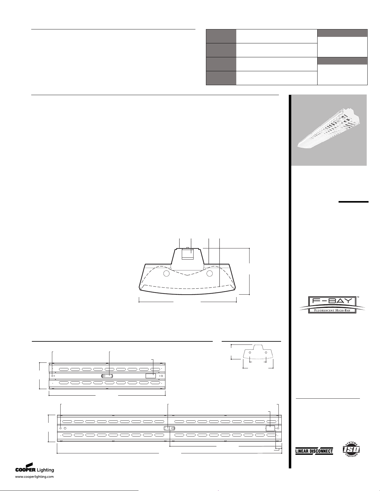
DESCRIPTION
The F-Bay I5 series is an outstanding solution for high mounting height
industrial or retail applications. The F-Bay I5 optic has been optimized to
provide maximum performance from T5 lamps. Optional uplight
component is provided to enable excellent ceiling uniformity. The I5's high
lumen package allows the benefits of fluorescent to be applied at high
mounting heights that were traditionally exclusive to H.I.D. The primary
benefits include exceptional color rendering, high system efficacy, 95%
lumen maintenance, long lamp life, instant on/instant re-strike, economical
dimming, and uniform brightness control. Primary applications include "big
box" retail, shopping malls, light industrial, school gymnasiums, etc.
A ... Construction
Specification grade full body
housing, end plates and socket
tracks are die formed 20 gauge
cold rolled steel in 4' or 8' lengths.
The housing features an integral
ballast channel that adds strength
and provides numerous KOs for
easy installation.
B ... Electrical
Class "P" ballasts are positively
secured by mounting bolts.
Rotorlock Bi-Pin lampholders and
optional top ballast access plate
enables service from above
without disturbing the internal
optics. Optional modular power
receptacle meets UL2459 and NEC
410.73 and is UL/cUL rated for
make and break under load from
outside the luminaire to speed
maintenance. UL/cUL listed.
Suitable for damp locations.
C ... Finish
Electrostatically applied baked
white enamel finish is preceded by
a multistage cleaning cycle, iron
phosphate coating with rust
inhibitor.
D ... Downlight/Uplight Optics
Optical modules are fully enclosed
inside housing to protect against
damage. Die formed reflectors are
faceted with two optical distribu-
tions: medium and wide. Medium
beam optical modules utilize 95%
specular aluminum finish. Open
downlight design optimizes
performance with uplight slots
available as an option for nominal
8% uplight component. An
optional attractive thin blade white
baffle adds longitudinal shielding.
A clear or frosted white acrylic lens
is also available. Optional heavy
duty wireguard can be used with
or without the lens or baffle.
Latched retention of shielding
optics (safety leader restraints)
allow for easy access.
Mounting
The I5 series is suited for surface,
suspension mounting with
optional wire hook and chain set,
stem or cable mounting. Top
connector box mounting is also
available. Narrow 11" housing
allows mounting within 12"
horizontally from the nearest edge
of the sprinkler deflector.
Options
Integral Occupancy Sensor
available and provides from 600
sq. ft. (MS) up to 1250 sq. ft. (MSO)
of coverage at a maximum
mounting height of 40'.
F-BAY
I5 Series
4' OR 8'
2 LAMPS
Retail/Light Industrial
T5 Linear Fluorescent Hi-Bay
Lighting System
E N E R G Y D A T A
Input Watts:
254T5 = (117)
8T254T5 = (229)
Luminaire Efficacy Rating
LER =68
Catalog Number: I5-254T5-TBW-UPL
Yearly Cost of 1000 lumens,
3000 hrs at .08 KWH = $3.55
* Reference the lamp/ballast data in the
Technical Section for specific lamp/ballast
requirements
** Consult Pre Sales Technical Support.
EB Ballast & T5HO Lamps
LAMPS CONTAIN MERCURY. DISPOSE ACCORDING
TO LOCAL, STATE OR FEDERAL LAWS
Safe and convenient means of
disconnecting power
4-15/16"
[126mm]
11" [280mm]
A B C
D
92" [2337mm]
46" [1168mm]
2-3/4" [70mm]
Top Connector Box
Mounting
11/16" [18mm] K.O.
for Cable or Pendant Mounting
11"
[280mm]
11/16" [18mm] K.O.
for Cable or Pendant Mounting
Access Plate
11"
[280mm]
11/16" [18mm] K.O. (2)
for Cable or Pendant Mounting
46" [1168mm]
Top Connector Box
Mounting
Access Plate
11" [280mm]
4-15/16"
[126mm]
4-5/8”
[118mm]
COOPER LIG H T I NG - METAL U X
®
Page 2
Specifications and Dimensions subject to change without notice.
PHOTOMETRICS
I5
C oe ffi ci en ts o f Ut il iz at io n
Effective floor cavity reflectance 20%
rc 80% 70% 50% 30% 10% 0%
rw 70 50 30 10 70 50 30 10 50 30 10 50 30 10 50 30 10 0
RCR
0
1
2
3
4
5
6
7
8
9
10
Z on al L um en S um ma ry
Zone Lumens %Lamp %Fixture
0-30
0-40
0-60
0-90
0-180
C an de la
Angle Along II 45° Across
0
5
10
15
20
25
30
35
40
45
50
55
60
65
70
75
80
85
90
I5-254T5-UPL
Electronic Ballast
(2) F54T5/HO/830K
lamps
4400 lumens
Spacing criterion:
(II) 1.2 x mounting
height, ( ) 1.1 x
mounting height
Efficiency 94.1%
Test Report:
I5254UPL.IES
LER =69
Yearly Cost of 1000
lumens, 3000 hrs at
.08 KWH = $3.48
3354 3354 3354
3332 3354 3360
3285 3370 3391
3207 3300 3155
3096 3060 2900
2954 2833 2704
2779 2599 2287
2575 2336 1875
2343 1922 1622
2087 1551 1345
1811 1297 1147
1522 1025 999
1225 819 872
926 705 621
639 501 421
386 289 225
184 119 41
42 14 12
1 12 12
109 109 109 109 106 106 106 106 99 99 99 92 92 92 86 86 86 83
102 98 95 92 98 95 92 89 89 87 85 84 82 80 79 77 76 74
94 88 82 78 91 85 80 76 80 76 73 75 72 69 71 69 66 64
87 78 72 67 84 76 70 65 72 67 63 68 64 61 64 61 58 56
80 70 63 58 77 68 62 57 65 59 55 61 57 53 58 54 51 49
74 63 55 50 71 61 54 49 58 52 47 55 50 46 52 48 45 43
68 57 49 44 66 55 48 43 53 46 42 50 45 41 48 43 40 38
63 51 44 38 61 50 43 38 48 42 37 46 40 36 43 39 35 33
58 46 39 34 56 45 38 33 43 37 32 41 36 32 39 35 31 29
54 42 34 29 52 41 34 29 39 33 28 37 32 28 36 31 27 25
50 38 31 26 48 37 31 26 36 30 25 34 29 25 33 28 24 23
2543 28.9 30.7
3964 45.0 47.9
6296 71.5 76.0
7340 83.4 88.6
8281 94.1 100.0
C oe ffi ci en ts o f Ut il iz at io n
Effective floor cavity reflectance 20%
rc 80% 70% 50% 30% 10% 0%
rw 70 50 30 10 70 50 30 10 50 30 10 50 30 10 50 30 10 0
RCR
0
1
2
3
4
5
6
7
8
9
10
Z on al L um en S um ma ry
Zone Lumens %Lamp %Fixture
0-30
0-40
0-60
0-90
0-180
C an de la
Angle Along II 45° Across
0
5
10
15
20
25
30
35
40
45
50
55
60
65
70
75
80
85
90
I5-254T5-TBW-UPL
(2) Electronic Ballasts
(2) F54T5/HO/830K
lamps
4400 lumens
Spacing criterion:
(II) 1.1 x mounting
height, ( ) 1.0 x
mounting height
Efficiency 90.7%
Test Report:
I5A254TBWUPL.IES
LER =68
Yearly Cost of 1000
lumens, 3000 hrs at
.08 KWH = $3.55
3503 3503 3503
3475 3476 3485
3387 3462 3516
3249 3358 3272
3084 3083 2986
2878 2790 2729
2633 2508 2279
2373 2198 1885
2093 1811 1611
1788 1470 1317
1469 1216 1116
1162 950 1027
858 760 857
572 651 612
370 467 443
245 276 248
145 175 66
62 103 34
0 52 22
105 105 105 105 102 102 102 102 95 95 95 88 88 88 82 82 82 79
98 94 91 88 94 91 88 86 85 83 81 80 78 76 75 74 72 70
90 84 79 75 87 82 77 73 77 73 70 72 69 66 68 65 63 61
84 76 69 64 81 73 68 63 69 64 61 65 61 58 62 59 56 54
77 68 61 56 74 66 60 55 62 57 53 59 55 51 56 52 49 47
71 61 54 48 69 59 53 48 56 50 46 53 48 45 51 47 43 41
66 55 48 43 64 54 47 42 51 45 41 49 44 40 46 42 39 37
61 50 43 38 59 49 42 37 46 41 36 44 39 35 42 38 34 32
57 45 38 33 55 44 38 33 42 36 32 40 35 31 38 34 30 29
52 41 34 29 51 40 33 29 38 32 28 36 31 27 35 30 27 25
49 37 31 26 47 37 30 26 35 29 25 33 28 25 32 27 24 22
2554 29.0 32.0
3903 44.3 48.9
6002 68.2 75.2
6995 79.5 87.6
7985 90.7 100.0
No internal fixture
access required for
installation or
disconnecting power.
Code Compliance
• UL/cUL Certified for Make/Break
under load (UL2549)
• Meets NEC requirements for
ballast disconnect (NEC 410.73G)
• Allows for addition of Occupancy
Sensor without hard connections
• Receptacles complete with
insulating dustcap
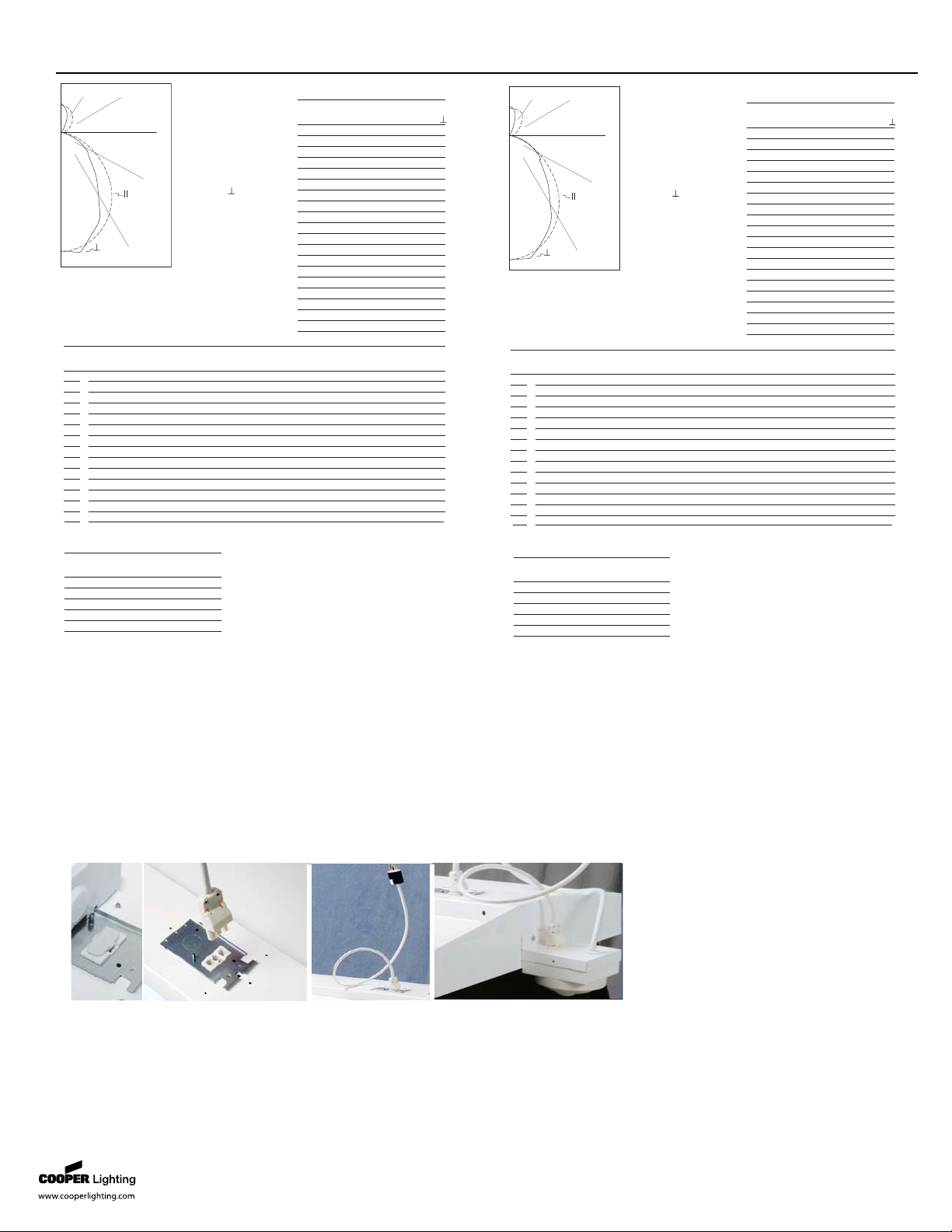
Cooper Lighting’s F-Bay Modular Power Supply option allows external fixture access for safe and easy servicing. There is no need
to remove lamps or reflectors to disconnect fixture power with F-Bay Modular Power Supply. Access to the individual fixtures
power supply allows servicing without turning off all the fixtures disrupting occupants. F-Bay Modular Power Supply is a time
saver in installation – simply plug & power.
1 2
Modular F-Bay Power Supply
1. Modular Power Supply Receptacle supplied
mounted into fixture Access Plate.
2. Modular Power Cord & Plugs in 120, 277, 347,
& 480V configurations for easy plug & power
into existing supply.
Modular Motion Sensor Option
supplied with Mounting Box and
Modular Power Supply Receptacle.
Metalux • Customer First Center • 1121 Highway 74 South • Peachtree City, GA 30269 • TEL 770.486.4800 • FAX 770.486.4801
08/02/2008 2:46:05 PM
ADF023027
Page 3

Specifications and Dimensions subject to change without notice.
ORDERING INFORMATION
SHIPPING INFORMATION
PI OPTION ORDERING INFORMATION
S AM PL E N UM B ER : 8 TI 5- 25 4T 5- TB W- UN V- EB T2 -U PL -U
NOTES:
(1)
Requires use of MC or MPC cord accessories, specify voltage for
plugs.
(2)
Use with wide distribution optic only.
(3)
Voltage must be specified when
ordered with plugs, motion sensors or emergency ballasts.
(4)
EBT ballast
systems suitable for operation in ambient environments up to 104°F (40°C).
(5)
Specify voltage.
(6)
For use with Top Connector Box options. See accessories.
(7)
2
lamp ballast configurations only in UNC High Ambient versions.
(8)
EHT ballast
systems suitable for ambient environments not to exceed 149°F (65°C) in open
uplight configurations and less lens option.
(9)
TAP option available with a
maximum of two ballasts, including EM battery pack.
(10)
Not for use in
gymnasiums or similar recreational facilities.
(11)
Dimming ballast must be
specified at time of order.
No. of Lamps
2=2 Lamps
Lamp Type
28T5=28W T5 (4') Lamps
54T5=54W T5HO (4') Lamps
Series
I5=T5 Industrial
Length
Blank=4' Length
8T=8' Length
Voltage
(3)
UNV=Universal
120/277 Voltage
UNC=Universal
347/480 Voltage
120V=120 Volt
277V=277 Volt
347V=347 Volt
480V=480 Volt
Shielding Options
Blank=Open
TBW=Thin White Baffle
FL=Frosted Acrylic Lens & Frame
(2)
CL=Clear Acrylic Lens Frame
ASY= Asymmetric Directional Louver
(2)
WG=Heavy Duty Wireguard
Distribution Optic
Blank=Medium (Specular Aluminum)
G=Wide (High Reflectance White)
Mounting Arrangement
Blank=Stand Alone
R=Continuous Row Mount
Options
I5 Lamps Installed
L5830=T5 Lamp, 85CRI 3000K
L5835=T5 Lamp, 85CRI 3500K
L5841=T5 Lamp, 85CRI 4100K
L5850=T5 Lamp, 85CRI 5000K
GL=Single Element Fuse
GM=Double Element Fuse
EL=Emergency Installed
(3)
Options
NUA=No Uplight Apertures In Housing
(Cannot be combined w/UPL)
UPL=Uplight Apertures
PI/CPI=Plug-In (1, 2 or 3)
(see ordering information below)
TILW=Tandem Inline Wiring
MWS=Modular Wiring System
MS=Aisle Coverage Motion Sensor
(5)
MSO=360° Coverage Motion Sensor
(5)
C3=3' Power Cord
C6=6' Power Cord
MP=Modular Power Receptacle
(1) (3)
PC3-=3' Power Cord & Plug (Specify Voltage)
TAP=Top Access Plate
(9)
TCBP=Top Connector Box Plate
(6)
Packaging
U=Unit Pack
PAL=Palletized
Out of Carton
PALC=Palletized
In Carton
Ballast Type
EBT =T5 or T5HO Linear Electronic Program
Rapid Start.
(4)
Total Harmonic Distortion < 10%
EHT
=T5 or T5HO Linear Electronic Program
Start High Ambient.
(7) (8)
Total Harmonic Distortion < 10%
DIM=Consult Factory
(11)
No. of Ballast
1, 2 or 3
No. of Ballast
1, 2 or 3
Accessories (order separately)
TCB=Top Connector Box
RH-1=Retrofit Hanger
FH-1=Fixture Hook
FL-1=Fixture Loop
SHK=Hook w/ Safety Screw
PC3-=3' Power Cord & Plug (Specify Voltage)
PC6-=6' Power Cord & Plug (Specify Voltage)
AYC-CHAIN/SET/U=(2) Hooks, 36" Chain Sets w/S-Hooks
(10)
GRIPPLE TOGGLE-=Single Toggle, #2 Cable (Specify 10' or 30')
GRIPPLE LOOP-=Loop Hanger, #2 Cable (Specify 10' or 30')
MC6=6' Modular Power Cord
MPC6=6' Modular Power Cord & Plug (Specify Voltage)
MMS-CPD1200H=Aisle Motion Sensor, Box, Modular
Power Receptacle (120/277V)
MMS-CPD500H=360° Motion Sensor, Box, Modular
Power Receptacle (120/277V)
Door Frames (for Field Installation)
I5-FRM/LENS=Frosted Acrylic Lens & Frame (I5)
I5-FRM/CL PK=Clear Acrylic Lens & Frame (I5)
WG/I5-4FT-B=Heavy Duty Wireguard (I5)
90800PPK=Thin White Blade Baffle (I5)
90801PPK=Asymmetrical Directional Louver
I5-254T5-TBW-UPL 15 lbs.
8TI5-254T5-TBW-UPL 30 lbs.
Catalog No. Wt.
BLK=Black Hot
PI1= Single
Circuit
NG= No Ground (ground
provided by fixture body)
WG= With Ground
(separate ground wire
in harness)
P I 1 - S i n g l e C i r c u i t P l u g - I n
S AM PL E N UM B ER : P I 1B L K- W G
BLK=Black Hot
BLU=Blue Hot
PI2= Two
Circuit
NG= No Ground (ground
provided by fixture body)
WG= With Ground (separate
ground wire in harness)
P I 2 - T w o C i r c u i t P l u g - I n
S AM PL E N UM B ER : P I 2B L K- W G
Leave Blank=Single
Neutral
/WHT=White Neutral
/GRY=Gray Neutral
Leave Blank=Single
Neutral
2NEU=Two Neutrals
BLK=Black Hot
BLU=Blue Hot
RED=Red Hot
PI3= Three
Circuit
NG= No Ground (ground
provided by fixture body)
WG= With Ground (separate
ground wire in harness)
P I 3 - T h r e e C i r c u i t P l u g - I n
S AM PL E N UM B ER : P I 3B L K- W G
Leave Blank=Single
Neutral
/WHT=White Neutral
/GRY=Gray Neutral
Leave Blank=Single Neutral
2NEU=Two Neutrals
For complete product data, reference the Fluorescent
Specification binder. Specifications & dimensions subject
to change without notice. Consult your Cooper Lighting
Representative for availability and ordering information.
Catalog Circuit
Number Number of Wired To
Suffix Circuits Ballast
PI 1 BLK 1 Black
PI 2 BLU 2 Blue
PI 2 BLK 2 Black
PI 3 RED 3 Red
PI 3 BLU 3 Blue
PI 3 BLK 3 Black
Catalog Numbering System
The PI System is available in sections up to 8' in length for continuous row wiring by simply plugging the sections
together. Each PI section is factory wired to the ballast leads. Color coding of wires is as follows:
PI-1 = One Circuit - 2 Wires: one black, one white
PI-2 = Two Circuits - 3 Wires: one black, one blue, one white
PI-3 = Three Circuits - 4 wires: one black, one blue, one red, one white
When ordering the PI2/PI3 System it is necessary to specify the number of fixtures required for each circuit. Each circuit in
fixture must be ordered as a separate line item, with a different hot wire color specified. All wiring to external feeds, using
cord or cord & plug, are responsibility of installing licensed contractor. Cord and cord & plug sets must be ordered
separately if PI option is chosen.
Metalux • Customer First Center • 1121 Highway 74 South • Peachtree City, GA 30269 • TEL 770.486.4800 • FAX 770.486.4801
08/02/2008 2:46:05 PM
ADF023027
 Loading...