

Page 1
Instruction Manual
Instrucciones
ENGLISH
GT Series
Serie GT
ESPAÑOL
Page 2
GT100H, GT150H
Congratulations. You have just purchased a Cooper Lighting dusk to dawn
lantern. This heavy-duty fixture is designed to provide years of convenience and
protection for your home or business.
HHooww iitt wwoorrkks
Your dusk to dawn security light features a light sensor that automatically turns
the light on at dusk and off at dawn.
WWhhaatt yyoouu nneeeed
• Hammer
• Screwdriver
• Drill with 3/16” drill bit
ENGLISH
• Adjustable wrench
• 1/2” diameter, flexible conduit (length depends on application)
• 1/2” watertight conduit connectors
• Wire connectors
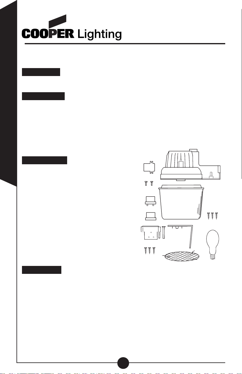
WWhhaatt’’ss iinncclluuddeed
• Fixture housing (A)
• One-piece optical lens assembly (B)
• (3) Lens assembly mounting screws (C)
• Bulb - MV or HPS (D)
• Access cover (E)
• (2) Access cover mounting screws (F)
• EZ-Mount™ bracket and pin (G)
• (3) Bracket mounting screws (H)
• Twist-lock photo control (I)
• Adjustable twist-lock photo control
cover (J)
• Bulb grille guard (K)
• Light shield (L)
WWhhaatt ttoo kknnoow
• For outdoor use only.
• cULus Listed for wet locations.
• Fixture must be connected to a 120 Volt, 60 Hz power source. Any other
connection voids warranty.
• Fixture should be installed by persons with experience in household wiring or
by a qualified electrician.
connecting the fixture to it, must be in accordance with the National Electrical
Code and local building codes.
• Always use same wattage and type of bulb that was included with the fixture.
Failure to do so will void the warranty.
s
d
d
E
F
I
J
L
G
H
K
w
The electrical system, and the method of electrically
Call for customer service and/or missing or damaged parts (800-334-6871)
2
GT75
A
B
C
D
Page 3
PPuuttttiinngg uupp yyoouurr ffiixxttuurre
NOTE: This fixture is intended to be conduit connected to a properly
installed and properly grounded metal weatherproof junction box (not provided). All conduit connections, conduit, and junction boxes (not provided)
should be UL Listed suitable for wet locations.
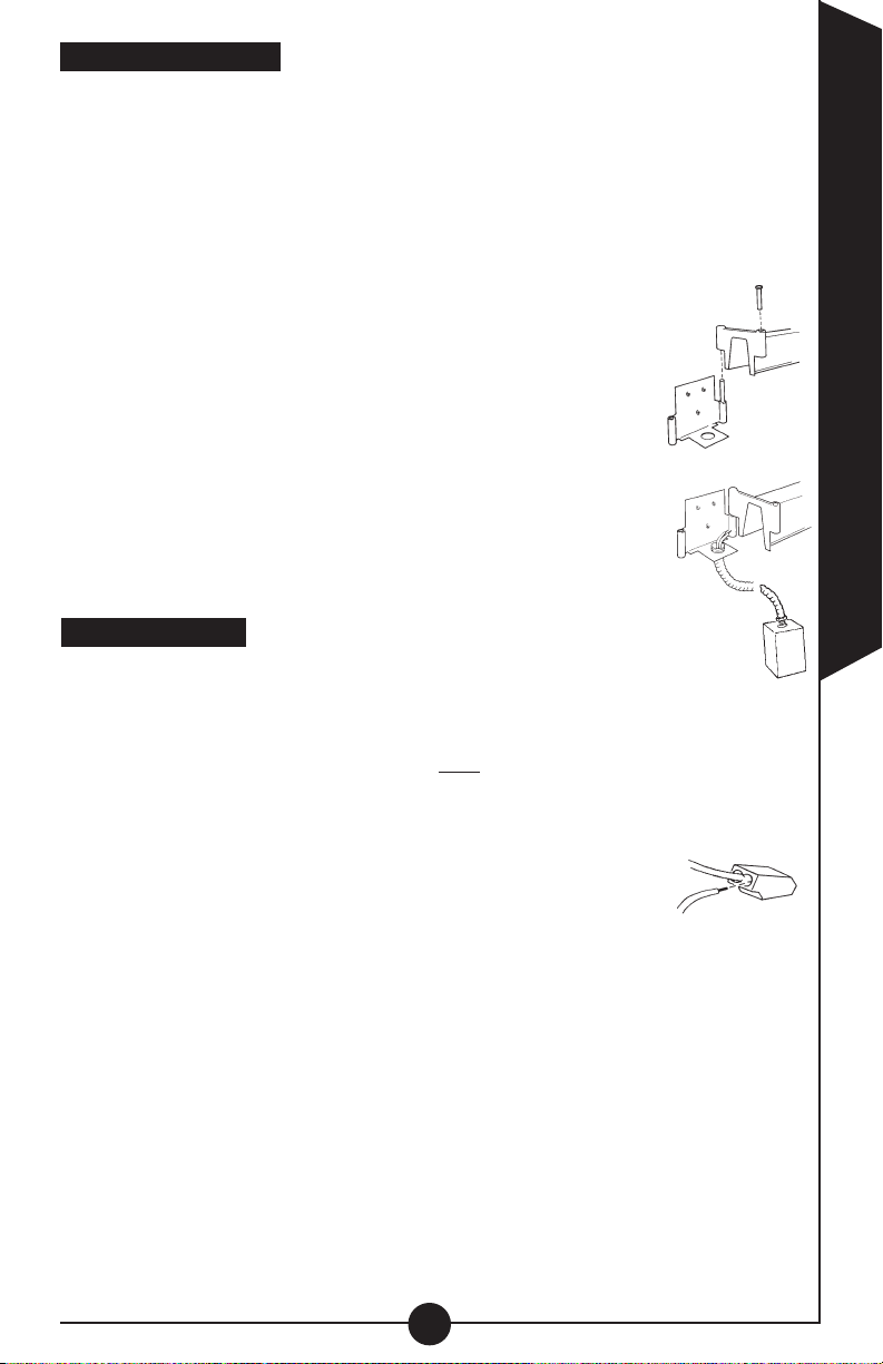
Using the EZ-Mount™ bracket, mark and drill holes for mounting. NOTE:
1.
The two holes in the bracket mark the top of the bracket, and when mounted
correctly, they should be above the single hole.
2. Mount the bracket to the surface using the three screws provided.
3. Hang the light fixture on the mounting bracket by inserting the
pin located on the right side of the mounting bracket inside the
hole located on the right side of the fixture arm (M). Fixture
should be swung to the right of the mounting bracket at this
point, so as not to interfere with the wiring of the fixture.
4. Install the first conduit connector (not provided) into the
knockout area of the mounting bracket (N). Tighten with
adjustable wrench.
5. Connect second conduit connector at the junction box (N).
6. Turn off the power at the main fuse/breaker box. Feed
supply wires into conduit, connecting one end inside junction
box, and the other end to the fixture. Make wiring connections
inside the fixture arm as described in
WWiirriinngg yyoouurr ffiixxttuurre
Before continuing - Make sure the power at the main fuse/breaker box
has been turned off.
If the supply wires coming from your house are solid, you can use the
Quick-connect™ wire system to attach your Regent light fixture. NOTE:
Quick connectors can only be used with solid supply wires.
1. Attach your ground supply wire to the ground wire coming from the fixture.
Secure with wire nut. (not provided)
2. Simply insert the black source supply wire into the quick con-
nector with the black wire coming from the fixture (O).
3. Insert the white source supply wire into the quick connector with
the white wire coming from the fixture (O).
4. Push both wires firmly into holes to insure that they are seated properly and
securely.
Proceed to “Attaching access cover and lens.”
If the supply wires coming from your house are stranded:
Remove the quick connectors from the end of the light fixture wires by turning
1.
them repeatedly from left to right while pulling. Repeat until they are both
removed.
electrical fixtures! These connectors are designed to withstand the tem
perature and voltage requirements of this Regent product only.
2.
Attach your ground supply wire to the ground wire coming from the fixture.
Secure with wire nut. (not provided)
3. Connect black fixture wire to black supply wire (hot). Secure with wire nut
(not provided).
e
M
N
“Wiring your fixture.”
e
O
Discard these connectors. Do not attempt to use with other
ENGLISH
-
3
Page 4
4. Connect white fixture wire to white supply wire (neutral). Secure with wire nut
(not provided).
5. Be careful to connect the wires correctly. Make sure no bare strands of wire
extend from the wire nut or other approved wire connectors (not supplied).
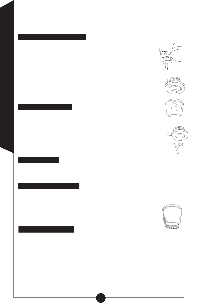
AAttttaacchhiinngg aacccceessss ccoovveerr aanndd lleenns
1. Attach the access cover to the light fixture using screws provid-
ed. Access cover should be positioned as shown in P.
Make sure all wiring is inside of the fixture arm before the
access cover is secured.
2. To attach the optical assembly to the housing, first insert the
three lens assembly mounting screws into the three holes
inside the fixture. Do not fully tighten the screws at this point.
Position the optical assembly over the fixture with slotted holes
over the mounting screws (Q). Carefully seat the optical assembly over the mounting screws and rotate the optical assembly
ENGLISH
clockwise until it stops. Tighten all screws.
IInnssttaalllliinngg tthhee lliigghhtt sshhiieelld
Before installing the lamp, position the light shield over the lamp
socket and press firmly into position (R). The shield is friction fitted
around the socket. The end of the light shield should be seated in
the lip of the lens. You can rotate the light shield in any direction to
block the light from the fixture.
touch the light shield while the lamp is on as the light shield gets
very hot. If the lamp has been on, allow the light shield time to cool
before touching.
IInnssttaalllliinngg tthhee llaammp
1. Screw the bulb securely into socket.
2. Back the bulb out one or two turns, then screw bulb back to insure proper
position in socket.
IInnssttaalllliinngg tthhee wwiirree ggrriillll gguuaarrd
1. First, locate the two wire tabs on the wire grill. Insert these two tabs in the
bottom of the lens.
2. Press the other end of the grill guard in position, and the wire clip
will lock the grill guard in place (S).
3. To remove the grill guard squeeze the wire clip and gently pull the
guard out.
IInnssttaalllliinngg tthhee lliigghhtt sseennssoor
1. Make sure the screw in the center of the receptacle (on top of the fixture)
is tight.
2. Match up the largest prong on the sensor to the largest slot in the receptacle.
3. Push the sensor down into the receptacle and twist clockwise 1/4 of a turn to
lock in place.
urn on the main power at the main fuse/breaker box.
4. T
power is initially turned on, the light may come on, even during daylight.
However, the light will turn off after two or three minutes and will only come on
p
s
NOTE:
d
NOTE: Do not attempt to adjust or
d
r
NOTE: When the
P
Q
R
S
4
Page 5

at dusk thereafter. If artificial light sources (such as car headlights) come in
contact with the photo control, it may activate the photo control and turn off the
fixture. If this occurs, the fixture will have to cool down for approximately five
minutes before it will come on again.
IInnssttaalllliinngg tthhee aaddjjuussttaabbllee pphhoottoo ccoonnttrrooll ccoovveer
r
The (optional) adjustable photo control cover provides additional flexibility in
allowing you to customize when your light turns on. The twist-lock photo control
is factory preset to turn your light fixture on at a predetermined outdoor light
level. If you would like for your light fixture to come on earlier, follow these simple instructions for attaching the adjustable photo control cover. First, remove
the cover from the package. The light sensor should already be attached to your
fixture. Position adjustable cover over the photo control (light sensor), and carefully press into place (T). You will hear it click over the photo control. You
will notice that there is a lens area on the photo control. Rotate the
T
cover to where the lens area is positioned in the front of the photo
control.
NOTE: You can locate the front of the photo control by the
arrow on the top of the twist-lock photo control. Rotate the cover so
that the heavily dotted area of the lens is in front of the photo control, which will turn your light fixture on earlier in the evening. To
make the fixture turn on slightly later, rotate the cover towards the lightly dotted
area of the lens.
OOppeerraattiinngg yyoouurr ffiixxttuurre
e
1. Turn on the power at the main fuse/breaker box.
2. Turn power on to the fixture. Your fixture should come on for 1 – 4 minutes,
then go off during daylight installation.
3. To test your fixture, cover the light sensor for 1 – 3 minutes. Your fixture
should come on. Uncover the sensor, and your fixture should turn off in
1 – 4 minutes.
YS ON
A
.
Is there power to the fixture?
• Has the circuit breaker tripped?
• Is the wall switch ON?
Is the bulb screwed in completely?
• Is the bulb good?
(Be careful not to overtighten)
Is the sensor functioning properly?
• Is light being reflected into the sensor, causing the fixture to
turn off?
• Is the sensor seated properly?
Is the wiring to the unit loose?
TURN OFF POWER BEFORE CONTINUING
• Check connections
• Is the unit properly grounded?
Is the light sensor receiving enough light?
Perform this simple test. Shine a flashlight into the light sen-
NOTE: There is approximately a 2 minute time delay
sor.
before the light will turn off. If the light turns off after approximately 2 minutes, then the light fixture is not getting enough
light. If this is the case, relocate the fixture, or use the
adjustable photo control cover to help shield the light.
WWhhaatt ttoo ddoo iiff .. .. .
LIGHT DOES NOT
COME ON
OR
LIGHT COMES ON FOR
ONLY A FEW SECONDS
LIGHT ST
OR
LIGHT CYCLES ON
AND OFF
ENGLISH
5
Page 6

Two year limited warranty
Cooper Lighting (“the Company”) warrants this product (“the product”)
against defects in material or workmanship for a period of two years from
date of original purchase, and agrees to repair or, at the Company’s option,
replace a defective product without charge for either replacement parts or
labor during such time. This does not include labor to remove or install fixtures.
This warranty is extended only to the original purchaser of the product. A
purchasers receipt or other proof of date of original purchase acceptable to
the Company is required before warranty performance shall be rendered.
This warranty only covers product failure due to defects in materials or workmanship which occurs in normal use. It does not cover the bulb or failure of
the product caused by accident, misuse, abuse, lack of reasonable care,
alteration, or faulty installation, subjecting the product to any but the specified electrical service or any other failure not resulting from defects in materials or workmanship. Damage to the product caused by separately purchased, non-Company brand replacement bulbs and corrosion or discol-
ENGLISH
oration of brass components are not covered by this warranty.
There are no express warranties except as described above.
THE COMPANY SHALL NOT BE LIABLE FOR INCIDENTAL, SPECIAL OR
CONSEQUENTIAL DAMAGES RESULTING FROM THE USE OF THE
PRODUCT OR ARISING OUT OF ANY BREACH OF THIS WARRANTY.
ALL IMPLIED WARRANTIES, IF ANY, INCLUDING IMPLIED WARRANTIES
OF MERCHANTABILITY AND FITNESS FOR A PARTICULAR PURPOSE,
ARE LIMITED IN DURATION TO THE DURATION OF THIS EXPRESS
WARRANTY. Some states do not allow the exclusion or limitation of incidental or consequential damages, or limitations on how long an implied warranty
lasts, so the above exclusions or limitations may not apply to you.
No other warranty, written or verbal, is authorized by the Company. This
warranty gives you specific legal rights, and you may also have other rights
which vary from state to state.
To obtain warranty service, please write to Cooper Lighting, 1121 Highway
74 South, Peachtree City, GA 30269. Enclose product model number and
problems you are experiencing, along with your address and telephone number. You will then be contacted with a solution, or a Return Goods
Authorization number and full instructions for returning the product. All
returned products must be accompanied by a Return Goods Authorization
Number issued by the Company and must be returned freight prepaid. Any
product received without a Return Goods Authorization Number from the
Company will be refused.
Cooper Lighting is not responsible for merchandise damaged in transit.
Repaired or replaced products shall be subject to the terms of this warranty
and are inspected when packed. Evident or concealed damage that is made
in transit should be reported at once to the carrier making the delivery and a
claim filed with them.
Customer First Center • 1121 Highway 74 South, Peachtree City, GA 30269 USA
Reproductions of this document without prior written approval of Cooper Lighting are strictly prohibited.
www.cooperlighting.com
Patent Pending
2005 Cooper Lighting
©
6
Page 7

GT75
GT100H, GT150H
Felicitaciones. Usted acaba de comprar una lámpara de vapor de
mercurio “amanecer-atardecer ”de grado industrial Regent. Este dispositivo extrafuerte está diseñado para ofrecer años de conveniencia y protección para su hogar o su negocio.
CCóómmoo ffuunncciioonna
La lámpara de seguridad amanecer-atardecer de incluye un
sensor de luminosidad que se enciende automáticamente al atardecer
y se apaga al amanecer.
QQuuéé ssee nneecceessiitta
• Martillo
• Destornillador
• Taladro con broca de 3/16 pulgadas (4.7mm)
• Llave inglesa ajustable
• Conducto portacables flexible de 1/2 pulgadas (12.7mm) de
diámetro (la longitud depende de la aplicación)
• Conectores del conducto portacables impermeable de
1/2 pulgadas (12.7mm)
• Conectores de cable
QQuuéé ssee iinncclluuyye
• Alojamiento del portalámparas (A)
• Ensamblaje óptico de una sola
pieza (B)
• (3) Tornillos de montaje del ensamblaje
del lente (C)
• El foco MV o HPS (D)
• Cubierta de acceso (E)
• (2) Tornillos de montaje de la cubierta
de acceso (F)
• Clavija y soporte de EZ-Mount™ (G)
• (3) Tornillos de montaje del soporte (H)
• Control fotoeléctrico que traba con un
movimiento de giro (I)
• Cubierta del control fotoeléctrico
ajustable (J)
• Protección de rejilla de la lámpara (K)
• Protección de la luz (L)
QQuuéé nneecceessiittaa ssaabbeer
Se debe utilizar en exteriores solamente.
•
• Aprobado por cULus para su utilización en áreas húmedas.
a
a
e
A
E
F
J
K
M
G
H
r
L
B
C
D
ESPAÑOL
Llame para solicitar servicio al cliente y/o piezas faltantes o dañadas (800-334-6871)
7
Page 8

• El portalámparas debe estar conectado a una fuente de energía de
120 Voltios, 60 Hz. Cualquier otro tipo de conexión anula la garantía.
• El portalámparas debe ser instalado por personas con experiencia en
cableado doméstico o por un electricista calificado. El sistema eléctrico
y el método de conexión eléctrica del portalámparas debe cumplir con
el Código Eléctrico Nacional y los códigos locales sobre edificios.
• Utilice siempre el mismo vatiaje y tipo del foco que se incluye con el
portalámparas. Si no lo hace se anulará la garantía.
IInnssttaallaacciióónn ddeell ppoorrttaalláámmppaarraas
NOTA: Este portalámparas ha sido diseñado para ser conectado a
través de un conducto portacables a una caja de conexiones (no se
suministra) de metal resistente a la intemperie adecuadamente instalada y conectada a tierra. El conducto portacables, sus conexiones
y las cajas de conexiones (no se suministran) deben ser adecuadas
para ubicaciones húmedas según las especificaciones UL.
1. Utilizando el soporte EZ-Mount™, marque y perfore los agujeros para
el montaje. NOTA: Los dos agujeros en el soporte marcan la parte
superior del soporte y cuando están montados correctamente deben
estar por encima del agujero individual.
2. Monte el soporte a la superficie utilizando los tres
tornillos que se suministran.
3. Cuelgue el portalámparas de la lámpara en el soporte
de montaje insertando la clavija ubicada en el lado
derecho del soporte de montaje dentro del agujero
ubicado en el lado derecho del brazo del portalámparas
(M). El portalámparas debe estar hacia la derecha del
soporte de montaje en este momento, de manera de no
interferir con el cableado del portalámparas.
4. Instale el primer conector del conducto portacables (no
suministrado) en el área del agujero ciego del soporte
de montaje (N). Apriételo con una llave inglesa.
5. Conecte el segundo conector del conducto portacables en la
caja de conexiones (N).
6. Desconecte la energía eléctrica en la caja principal del
desconector automático/fusibles. Coloque los cables de suministro
en el conducto portacables, conectando un extremo dentro de la caja
de conexiones y el otro extremo al portalámparas. Realice las conexiones de cableado dentro del brazo del portalámparas como se
describe en “Cableado del portalámparas.”
CCaabblleeaaddoo ddeell ppoorrttaalláámmppaarraas
Antes de continuar - Asegúrese de que la energía de la caja de
fusibles/interruptores principal ha sido apagada.
ESPAÑOL
Si los cables de energía provenientes de su casa son sólidos,
puede utilizar el sistema de cableado Quick-connect
conectar su portalámparas de la lámpara Regent. NOTA: Los conec-
tores rápidos se pueden utilizar solamente con hilos conductores de
suministro de cable sólido.
s
s
para
™
M
N
8
Page 9

1. Conectar el alambre de puesta a la tierra con el alambre
verde de puesta a la tierra del aparato. Asegúrelo con
la tuerca para cables. (no se incluye)
2. Simplemente inserte el cable de suministro negro en
el conector rápido con el cable negro que viene del
portalámparas (O).
3. Inserte el cable de suministro blanco en el conector rápido con el
cable blanco que viene del portalámparas (O).
4. Empuje ambos cables firmemente en los agujeros para asegurar que
estén colocados segura y adecuadamente.
Proceda a “Conexión de la cubierta de acceso y del lente.”
Si los cables de suministro provenientes de su casa están trenzados:
1. Retire los conectores rápidos del extremo de los cables del portalám-
paras de la lámpara torciéndolos repetidas veces de izquierda a
derecha mientras que los hala. Repita este procedimiento hasta que
haya retirado ambos. Deseche estos conectores. ¡No intente uti-
lizarlo con otros artefactos eléctricos! Estos conectadores están
diseñados para soportar los requisitos de temperatura y voltaje
de este producto Regent solamente.
2. Conectar el alambre de puesta a la tierra con el alambre verde de
puesta a la tierra del aparato. Asegúrelo con la tuerca para cables.
(no se incluye)
3. Conecte el cable negro del portalámparas al cable negro de sumin-
istro (activo). Asegúrelo con la tuerca para cables (no suministrado).
4. Conecte el cable blanco del portalámparas al cable blanco de sumin-
istro (neutral). Asegúrelo con la tuerca para cables (no suministrado).
5. Asegúrese de que conecta los cables correctamente. Asegúrese de
que no salen hilos de cables pelados de las tuercas para alambres o
de otros conectores de alambres aprobados (no se incluye).
O
CCoonneexxiióónn ddee llaa ccuubbiieerrttaa ddee aacccceessoo yy ddeell lleenntte
1. Conecte la cubierta de acceso al portalámparas
utilizando los tornillos suministrados. La cubierta de
acceso se debe colocar como se muestra en la P.
NOTA: Asegúrese de que todo el cableado se
encuentra dentro del brazo del portalámparas antes
de asegurar la cubierta de acceso.
2. Para conectar el ensamblaje óptico al alojamiento,
inserte primero los tres tornillos de montaje del
ensamblaje del lente en los tres agujeros dentro del
portalámparas. No apriete completamente los tornillos
en este momento. Coloque el ensamblaje óptico
sobre el portalámparas, con los agujeros para tornillos
de cabeza ranurada sobre los tornillos de montaje (Q).
Coloque cuidadosamente el ensamblaje óptico sobre
los tornillos de ensamblaje y rote el ensamblaje óptico
en dirección a las agujas del reloj hasta que se detenga. Apriete
todos los tornillos.
e
9
P
ESPAÑOL
Q
Page 10

IInnssttaallaacciióónn ddee llaa pprrootteecccciióónn ddee llaa lluuz
1. Antes de instalar la lámpara, coloque la protección
de la luz sobre el enchufe de la lámpara y presione
firmemente en su posición (R). La protección se coloca por fricción alrededor del enchufe. El extremo de la
protección de la lámpara debe colocarse en el borde
del lente. Usted puede rotar la protección de la luz en
cualquier dirección para bloquear la luz del portalámparas.
con la lámpara encendida ya que la protección de la lámpara se pone
muy caliente. Si la lámpara ha estado encendida, dele tiempo a la
protección de la lámpara para que se enfríe antes de tocarla.
IInnssttaallaacciióónn ddeell ffoocco
1. Enrosque bien el foco en el casquillo.
2. Desenrósquela una o dos vueltas y vuélvala a enroscar para
asegurarse de que esté correctamente colocada en el casquillo.
IInnssttaallaacciióónn ddee llaa pprrootteecccciióónn ddee rreejjiillllaa ddee aallaammbbrre
1. Primero ubique las dos lengüetas de alambre en la rejilla de alambre.
Inserte estas dos lengüetas en la parte inferior del lente.
2. Presione el otro extremo de la protección de rejilla en su
posición y la presilla de alambre asegurará la protección de
rejilla en su lugar (S).
3. Para quitar la protección de rejilla apriete la presilla de
alambre y con cuidado saque la protección.
IInnssttaallaacciióónn ddeell sseennssoorr ddee lluuz
1. Asegúrese de que el tornillo en el centro del tomacorriente (o en la
parte superior del portalámparas) está apretado.
2. Haga corresponder la espiga de contacto más larga en el sensor con
la ranura más grande en el tomacorriente.
3. Empuje hacia abajo el sensor en el tomacorriente y dele 1/4 de
vuelta en dirección a las agujas del reloj para asegurarlo en su lugar.
4. Encienda la energía principal en la caja principal de fusibles/interrup-
tores.
puede encenderse, aún durante la luz del día. Sin embargo, la luz se
apagará después de dos o tres minutos y se encenderá solamente a
partir del atardecer. Si fuentes de luz artificial (como las luces de un
automóvil) establecen contacto con el control fotoeléctrico, se puede
activar el control fotoeléctrico y apagar el dispositivo. Si esto ocurre,
tendrá que enfriarse durante cinco minutos aproximadamente antes
de que se encienda de nuevo.
IInnssttaallaacciióónn ddee llaa ccuubbiieerrttaa ddeell ccoonnttrrooll ffoottooeellééccttrriiccoo aajjuussttaabblle
ESPAÑOL
1. La cubierta del control fotoeléctrico ajustable (opcional) ofrece mayor
flexibilidad al permitirle personalizar el momento en que se encienden
sus luces. El control fotoeléctrico que traba con un movimiento de
giro viene de fábrica preestablecido para encender su dispositivo en
un nivel de luz predeterminado. Si desea que se encienda más tem
prano, siga estas simples instrucciones para conectar la cubierta del
NOTA: No intente ajustar o tocar la protección de la lámpara
o
z
NOTA: Cuando se enciende la energía inicialmente, la luz
z
e
e
R
S
-
10
Page 11

control fotoeléctrico ajustable. Primero, saque la cubierta del paquete.
El sensor de luz debe estar ya conectado a su portalámparas.
Coloque la cubierta ajustable sobre el control fotoeléctrico y
con cuidado presiónela en su lugar (T). La oirá encajar en el
control fotoeléctrico. Verá que hay un área del lente en la
cubierta del control fotoeléctrico. Rote la cubierta hacia
donde está ubicada el área del lente al frente del control
fotoeléctrico. NOTA: Usted puede ubicar el frente del control
fotoeléctrico por la flecha que se encuentra en la parte superior del
control fotoeléctrico que traba con un movimiento de giro. Rote la
cubierta de manera que el área con muchos más puntos del lente
quede al frente del control fotoeléctrico, el cual encenderá su dispositivo más temprano en la tarde. Para hacer que se encienda un poco
más tarde, rote la cubierta hacia el área del lente con menos puntos.
OOppeerraacciióónn ddee ssuu ppoorrttaalláámmppaarraas
s
1. Active la fuente de alimentación en la caja de fusibles/interruptor
automático.
2. Encienda la corriente del aparato. Tu unidad estará lista entre 1 y 4
minutos, deberás consederar para su instalación un día soleado.
3. Para probar tu unidad cubre el sensor de luz entre 1 y 3 minutos.
Posteroirmente la unidad estará lista para funcionar. Descobre el
sensory y deberas desconector la unidad entre 1 y 4 minutos.
QQuuéé hhaacceerr ssii .. .. .
.
T
LA LUZ NO SE ENCIENDE
O
LA LUZ SE ENCIENDE
SÓLO DURANTE UNOS
SEGUNDOS
LA LUZ QUEDA
ENCENDIDA
O
SE APAGA Y SE
ENCIENDE
¿Llega electricidad al portalámparas?
• ¿Ha saltado el interruptor automático de la casa?
• ¿Está encendido el interruptor de pared?
¿Está el foco bien apretada?
• ¿Está en buen estado el foco?
(Tenga cuidado de no quebrar los pasadores el
foco al colocarla)
¿Está funcionando el sensor correctamente?
• ¿Se está reflejando luz en el sensor, lo que hace
que el portalámparas se apague?
• ¿Está el sensor colocado correctamente?
¿
Están los cables de la unidad sueltos?
APAGUE LA ENERGÍA ANTES DE CONTINUAR
• Revise las conexiones
• ¿Está la unidad conectada a tierra
adecuadamente?
¿
Recibe el sensor luz suficiente?
Realice esta simple prueba. Ilumine una linterna en
el sensor de la lámpara. NOTA: Existe un tiempo de
demora de aproximadamente dos minutos antes de que
se apague la luz. Si la luz se apaga después de dos
minutos aproximadamente, el portalámparas no está
obteniendo suficiente luz. Si este es el caso, reubique
el portalámparas o utilice la cubierta del control fotoeléc-
trico ajustable para ayudar a proteger la lámpara.
ESPAÑOL
11
Page 12

Garantía Limitada por dos años
Cooper Lighting (‘la Compañía’) garantiza este producto (‘el producto’) contra
defectos de material o fabricación, por un período de dos años a partir de la
fecha de la compra original, y acuerda reparar o, a opción de la Compañía,
reemplazar un producto defectuoso sin cargo, ya sea por las piezas de reemplazo o la mano de obra correspondiente, durante dicho tiempo. Esto no incluye la
mano de obra necesaria para retirar o instalar artefactos.
Esta garantía se extiende únicamente al comprador original del producto. Antes
de efectivizar el cumplimiento de la garantía, se requiere del comprador un recibo u otra prueba de la fecha de la compra original, que sea aceptable para la
Compañía.
Esta garantía cubre únicamente las fallas del producto debidas a defectos en
sus materiales o fabricación, que ocurran durante su uso normal. No cubre la
lámpara, ni las fallas del producto causadas por accidente, mal uso, maltrato,
falta de cuidado razonable, alteración o instalación defectuosa, conexión del producto a un suministro eléctrico distinto del especificado, o cualquier otra falla que
no sea consecuencia de defectos en los materiales o en la fabricación. Los
daños causados al producto por lámparas de repuesto adquiridas separadamente, que no sean de la marca de la Compañía, y por corrosión o decoloración
de los componentes de latón, no están cubiertos por esta garantía.
No existen otras garantías expresas más que la descripta anteriormente.
LA COMPAÑIA NO SERA RESPONSABLE DE DAÑOS INCIDENTALES, ESPE-
CIALES O CONSIGUIENTES QUE RESULTEN DEL USO DEL PRODUCTO O
SE ORIGINEN EN CUALQUIER INFRACCION A ESTA GARANTIA. TODA
GARANTIA IMPLICITA, SI LA HUBIERA, INCLUYENDO GARANTIAS IMPLICITAS DE COMERCIABILIDAD Y ADECUACION PARA UN FIN PARTICULAR,
ESTAN LIMITADAS EN DURACION A LA DURACION DE ESTA GARANTIA
EXPRESA. Algunas jurisdicciones o estados no permiten la exclusión o limitación de daños incidentales o consiguientes, o las limitaciones sobre la
duración de una garantía implícita, de modo que las exclusiones o limitaciones
indicadas pueden no ser aplicables a su caso.
La Compañía no autoriza ninguna otra garantía, ya sea escrita o verbal. Esta
garantía le otorga derechos legales específicos, y es posible que usted tenga
otros derechos, que pueden variar de una jurisdicción o estado, a otro.
Para obtener servicio en garantía escriba a Cooper Lighting, 1121 Highway 74
South, Peachtree City, GA 30269, Estados Unidos de América. Indique el
número de modelo del producto y los problemas que experimenta, además de
su dirección y número de teléfono. Será contactado entonces para obtener una
solución, o un número de Autorización de Retorno de Mercancías (‘Return
Goods Authorization’) e instrucciones completas para regresar el producto.
Todos los productos que se regresen deben estar acompañados por el Número
de Autorización de Retorno de Mercancías emitido por la Compañía, y deben
regresarse con el flete previamente pagado. Todo producto que se reciba sin el
Número de Autorización de Retorno de Mercancías emitido por la Compañía,
será rechazado.
Cooper Lighting no se hace responsable por los daños que puedan experimentar
las mercancías en tránsito. Los productos reparados o reemplazados estarán
sujetos a los términos de esta garantía, y se inspeccionan al embalarlos. Ante
cualquier daño evidente u oculto ocurrido en tránsito, debe informarse enseguida
al transportista que realiza la entrega, y presentarle el correspondiente reclamo.
ESPAÑOL
30269 USA
Customer First Center • 1
La reproducción de este documento sin la aprobación previa por escrito de Cooper Lighting está estrictamente prohibida.
121 Highway 74 South, Peachtree City
www.cooperlighting.com
patente pendiente
2005 Cooper Lighting
©
12
, GA
07/05 325-1508
 Loading...