

Page 1
049-282
Sure-Lites
Installation Instructions for the Sure-Lites SELW29SD Emergency Light with
Self Diagnostics
WARNING
Risk of Fire / Electric Shock
If not qualifi ed, consult an electrician.
Important Safeguards
When using electrical equipment, basic safety precautions
should always be observed including the following:
• READ AND FOLLOW ALL SAFETY INSTRUCTIONS
• Do not use in hazardous locations, or near gas or electric heaters.
• Do not let power supply cords touch hot surfaces.
• Use caution when servicing batteries. Battery acid can
cause burns to skin and eyes. If acid is spilled on skin
or in eyes, fl ush acid with fresh water and contact a
physician immediately.
• Do not use this equipment for other than the intended
use.
• Installation is to be performed only by qualifi ed person-
nel.
• Install in accordance with National Electric Code and
local regulatory agency requirements.
• The use of accessory equipment not recommended by
the manufacturer may cause an unsafe condition.
• Equipment should be mounted in locations and at
heights where it will not readily be subjected to tampering by unauthorized personnel.
• SAVE THESE INSTRUCTIONS
WARNING
Risk of Electric Shock
Disconnect power at fuse or circuit breaker before installing
or servicing.
INSTALLATION
1. De-energize the circuit at the junction box (J-box)
where the emergency light is to be installed.
2. Open the emergency light by inserting a fl at screw-
driver in the two slots on the side of the unit, then
turning to separate housing from the backplate.
3. To mount to a junction box - Drill out the appropriate
mounting pattern and the wire pass hole in the backplate and the back gasket to fi t the J-box being used.
4. To mount to conduit – Unscrew the ½” NPT plug located at the top of the fi xture and screw in the user-sup-
plied conduit hub.
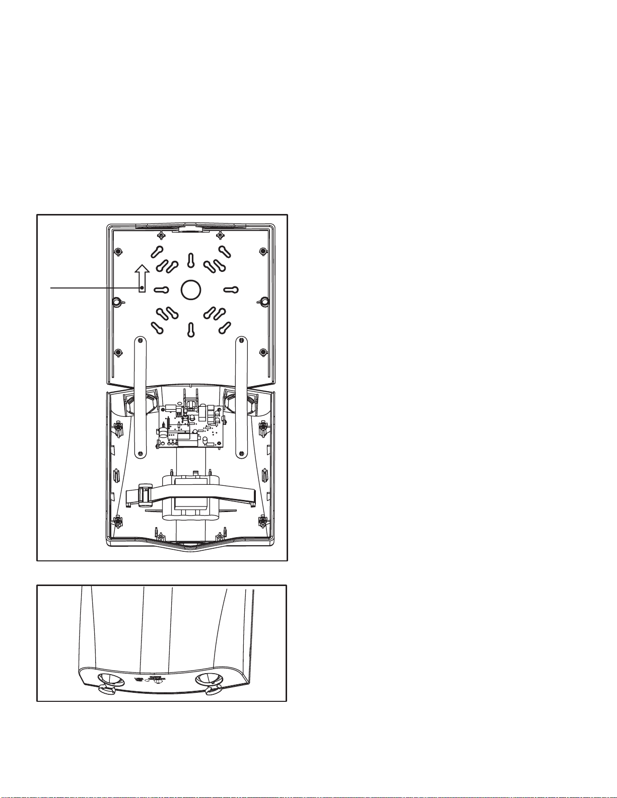
5. Once the backplate is secured, the housing can be
held in place during installation with the help of the two
plastic strips (see Fig. 1 next page).
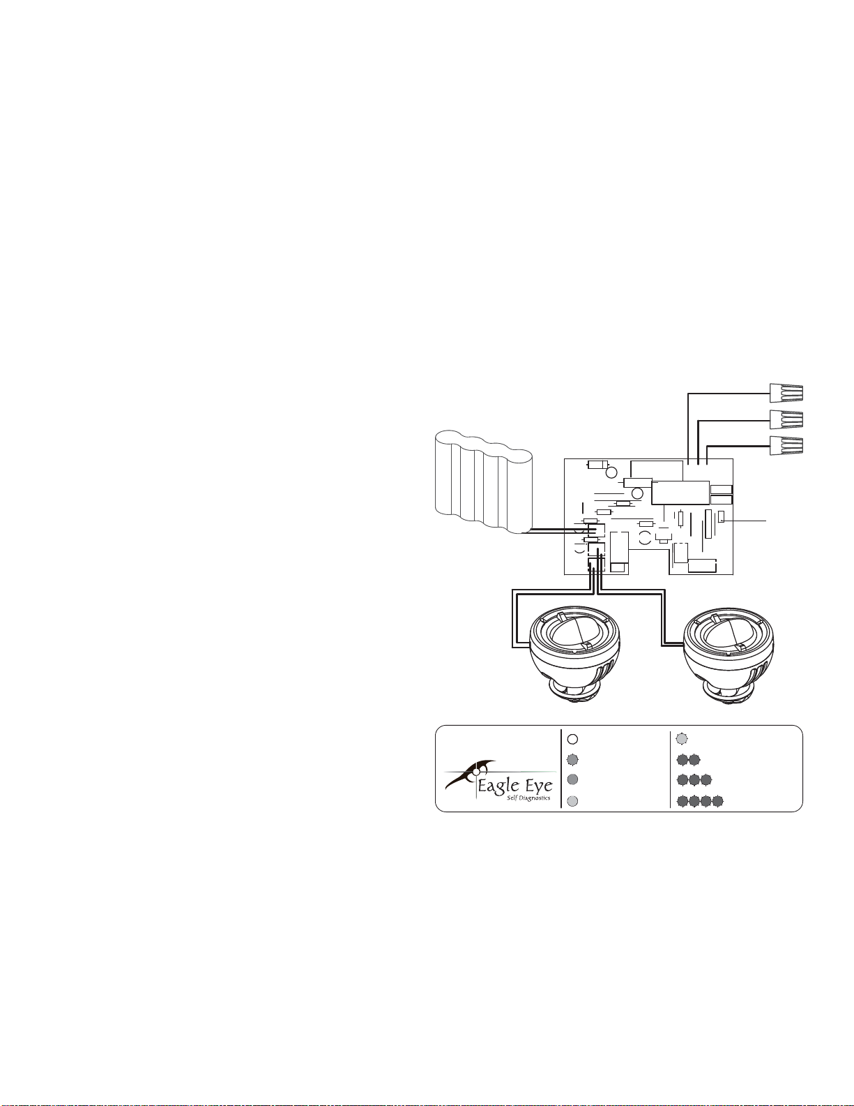
6. Connect the incoming wires to the SELW29SD power
supply wires using the wire nuts provided. Connect the
white wire to neutral. If using 120V, connect the black
wire to the hot lead. If using 277V, connect the orange
wire to the hot lead. Cap the unused lead. Secure the
emergency light to the wall and/or junction box using
installer supplied hardware.
7. Complete the battery connection and snap the cover
onto the backplate.
8. Energize AC supply. The test button should illuminate,
and LED heads will illuminate briefl y when the test
button is pushed.
9. Adjust the heads as needed. The SELW29SD lenses
utilize a highly directional beam, and the lenses can be
rotated to adjust the beams to the front or sides of the
fi xture (see Fig. 2 next page).
Page 2
ACTIVATING TIME DELAY
OPERATION
The SELW29SD has an integrated time delay circuit that
allows them to remain in emergency mode 15 minutes after
power is restored.
To activate the time delay, remove the jumper on the circuit
board labeled TDI/J1.
Figure 1
FOR BEST
RESULTS MOUNT
WITH ARROW
FACING UP
Figure 2
The Sure-Lites Eagle Eye Self Diagnostics is continuously monitoring your emergency fi xture, and will signal any
failure through the 3 color indicator LED.
INITIAL OPERATION
When the unit is fi rst powered up, it will go into a 24 hour
fast charge, indicated by the indicator LED pulsing green.
Once the unit has fully charged, it will perform a self calibration, after which the LED will change to steady green,
indicating the unit is fully charged and fl oat charging the
battery to maintain readiness.
AUTOMATIC TESTING
The unit will perform a battery capacity, lamp/LED, and
charge circuit test every 30 days for 30 seconds. During
this time, the indicator LED will change to a steady yellow.
It will perform a full battery capacity (90 minute) test once
per year. During this time, the indicator LED will change to
a blinking yellow.
MANUAL TESTING
• 10 Second “Installation” test – Press and release the
test button once during fast charge (blinking green) to
initiate a 10 second quick test. The sign will switch to
emergency mode for 10 seconds allowing the installer
to verify proper installation of the unit, and the LED
indicator will turn solid yellow.
• 30 Second Test - Press and release the test button
once during fl oat charge (steady green). The indica-
tor LED will turn steady yellow to indicate the unit is
performing a 30 second test of the batteries and lamps/
LEDs.
• 90 Minute Test - Press and release the test button a
second time during a 30 second test (steady yellow) to
change to a 90 minute test. During this test, the LED
indicator will change to blinking yellow, and the circuit
will perform a full battery capacity, charge circuit, and
LED test.
• Canceling Test – Press and release the test button
during the 90 minute test (fl ashing yellow) to return the
fi xture to its original state (fast charge or fl oat charge).
LASER TEST:
The SELW29SD is equipped with a Laser Test function,
that allows the unit to be manually tested without the need
to physically press the test button. Shining a laser pointer
in the hole marked “LASER TEST” on the bottom of the
unit has the same effect as a press and release of the test
button.
SEL-SD Emergency Lights Installation Instructions www.eaton.com/lighting 2
Page 3
CLEARING FAILURE CODES:
• A battery failure (LED two blink red) can be cleared by
replacing the battery. Disconnecting the battery and AC
power, or performing a full 90 minute discharge, will
reset the error code, however, it will return if the battery
is faulty.
• Charge Circuit (LED three blink red) and lamp/LED
failure (LED four blink red) will clear when the unit successfully passes a manual or automatic 30 second test.
INDICATORS:
• LED Off - No power to unit, emergency mode.
• LED Steady Green - Unit is fully charged and is fl oat
charging the battery to maintain readiness.
• LED Green Pulse - Unit is in a 24 hour fast charge of
the battery.
• LED Two Blink Red - Battery has failed a capacity test,
or the battery is disconnected. See “Clearing Failure
Codes” above.
• LED Three Blink Red - Battery charge circuit has failed.
See “Clearing Failure Codes” above.
• LED Four Blink Red - Lamps have burned out, or on
an EXIT/Combo, 50% or more of the LEDs have failed.
See “Clearing Failure Codes” above.
• LED Steady Yellow - 30 second test or 10 second quick
test (Fast Charge only).
• LED Blinking Yellow - 90 minute test
MAINTENANCE:
None required. Replace the batteries as needed according
to ambient conditions. Equipment should be tested every
30 days in accordance with local codes.
TROUBLE SHOOTING GUIDE
If LED heads or charge indicator LED does not illuminate,
check the following:
1. Check AC supply – verify that unit has 24 hour AC
supply.
2. Unit is shorted or battery is not connected.
3. Battery discharged. Permit unit to charge for 24 hours
and then re-test.
4. If following the above trouble shooting hints does not
solve your problem, contact your local Eaton Light representative for assistance
ORANGE LEAD - TO 277V
BLACK LEAD - TO 120V
277
JMP9
R13
JMP14
CN5
PR1
WHITE LEAD - TO NEUTRAL
N
120
MOV1
MOV2
CN4
J1
TDI
JMP10
JMP12
ICSP
JMP11
LED/SW
TIME DELAY
JUMPER
BATTERY
CHARGER/DRIVER PCB
D5
C9
c
JMP5
R15
JMP4
R7
Q5
R18
Q1
LAMPS
JMP13
BATT
+
C6
F1
+
C8
R10
C7
JMP6
JMP7
JMP8
R30
LED1
JK1
SW1
NOTE: Servicing of any parts should be performed by quali-
fi ed personnel. Only use replacement parts supplied by Eaton Light. Use of unauthorized parts may void the warranty.
CAUTION: This equipment is furnished with a sophisticated
low voltage battery dropout circuit to protect the battery
from over discharge after its useful output has been used.
Allow 24 hours recharge time after installation or power
failure prior to 90 minute testing.
SEL-SD Emergency Lights Installation Instructions www.eaton.com/lighting3
SURE-LITES
LED HEADS
OFF - EMERGENCY
MODE / POWEROFF
STEADY BLINK
GREEN - FAST
CHARGE
STEADY GREEN -
FULL / FLOAT
CHARGE
STEADY YELLOW -
QUICK TEST
STEADY BLINK YELLOW
- 90 MINUTE TEST
2 BLINK RED -
BATTERY FAILURE
3 BLINK RED - CHARGE
CIRCUIT FAILURE
4 BLINK RED - LAMP/
LED FAILURE
Page 4

Eaton
1121 Highway 74 South
Peachtree City, GA 30269
eaton.com/lighting
© 2015 Eaton
All Rights Reserved
Printed in USA
Eaton is a registered trademark.
All trademarks are property of
their respective owners.
 Loading...