

Page 1
2-Lamp
COOPER LIGHTING
ELECTRONIC DIMMING BALLASTS WITH ANALOG DIMMING CONTROL (0-10V) FOR TWO (2) LAMP FIXTURES
Cooper Controls Electronic Dimming Ballasts, powered by Fifth Light Technology, offer cost-effective, reliable dimming control for linear fluorescent lamps,
down to 3% for T5 and T8 lamps. These two-lamp ballasts cover a range of lamp types and lengths installed in Cooper Lighting fluorescent lighting fixtures.
All of the ballasts have programmed rapid start circuits, active power factor correction and lamp end-of-life protection. The ballasts are ideal for direct
integration with Cooper Controls solutions and compatible with a wide variety of analog controls and photocells.
FEATURES
Ideal for use with 0-10V energy-management systems, daylight
harvesting and local controls
Helps meet energy codes, including ASHRAE 90.1 and California
Title 24, when applied properly
Compatible with Energy-Saving and Low-Mercury Lamps Active Power-factor Correction for maximum energy savings
120-277V input for easy ordering and universal application Control inputs protected against mis-wiring with built-in line voltage protection
Dimming Range: 3% for T5 or T8 Starts at any dimmed level without flashing
STANDARDS AND LISTINGS
cULus Listed (Class P, Type 1 Outdoor, Type CC) Meets FCC CFR 47 Part 18 for EMI and RFI Non-consumer limits
Meets ANSI Standard C82.11 No PCBs
Meets ANSI Standard C62.41 Sound Rated, Class A
Ballast must be grounded in accordance with national and local
electrical codes
0-10V Dimming Ballast Specifications
Programmed Rapid Start maximizes lamp life
End-of-lamp-life Shutdown circuit with Auto-reset for safe, long-term operation
Control can be wired as Class I or Class II
PERFORMANCE AND ELECTRICAL CHARACTERISTICS FOR ALL TWO-LAMP BALLASTS
Minimum Dimming Temperature: 50°F (10°C) Minimum Starting Temp: 0°F (-18°C)
Maximum Ambient Temperature: 104°F (40°C) Maximum Case Temperature: 167°F (75°C)
Ballast Factor: 1.0 Power Factor: > .98
Crest Factor: < 1.7 Total Harmonic Distortion(THD): < 10%
PERFORMANCE AND ELECTRICAL CHARACTERISTICS BY LAMP TYPE
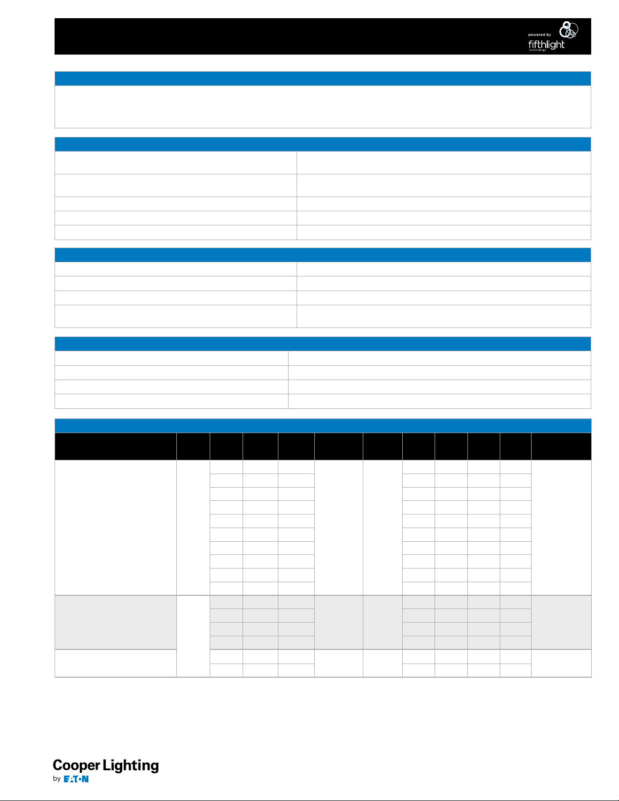
Cooper Part
Number
FLT-232PSUNV010-R1-C T8
FLT-228PSUNV010-R1-C
FLT-214PSUNV010-R1-C
Lamp
Type
T5
Lamp
Type
T8U 32 U 0.484 0.206 1.54 1.54
T8U 31 U 0.465 0.2 1.54 1.54
T8U 24 U 0.348 0.152 1.89 1.89
T8U 16 U 0.253 0.105 2.66 2.66
T8ES 32 (30) 4 0.455 0.194 1.54 1.54
T8ES 32 (25) 4 0.392 0.183 1.89 1.89
T5ES 25 4 0.48 0.21 1.75 1.80
Lamp
Watt
T8 32 4
T8 28 4 0.425 0.183 1.89 1.89
T8 25 3 0.369 0.16 1.89 1.89
T8 17 2 0.253 0.105 2.66 2.66
T5 28 4
T5 28 4 0.52 0.22 1.59 1.64
T5 21 3 0.4 0.17 2.13 2.17
T5 14 2
T5 14 2 0.27 0.12 3.13 3.13
Lamp
Length
Lamp
Operation
Series 120-277
Series 120-277
Series 120-277
Voltage
Input
Amps
-120V
0.489 0.21 1.54 1.54
0.52 0.22 1.59 1.64
0.27 0.12 3.13 3.13
Input
Amps
-277V
BEF -
120V
BEF -
277V
Dimming
Performance
3%
3%
3%
ACF130940 8/5/14
Page 2
1.71
16.88
2-Lamp
COOPER LIGHTING
DIMMING CONTROL APPLICATIONS AND SPECIFICATIONS
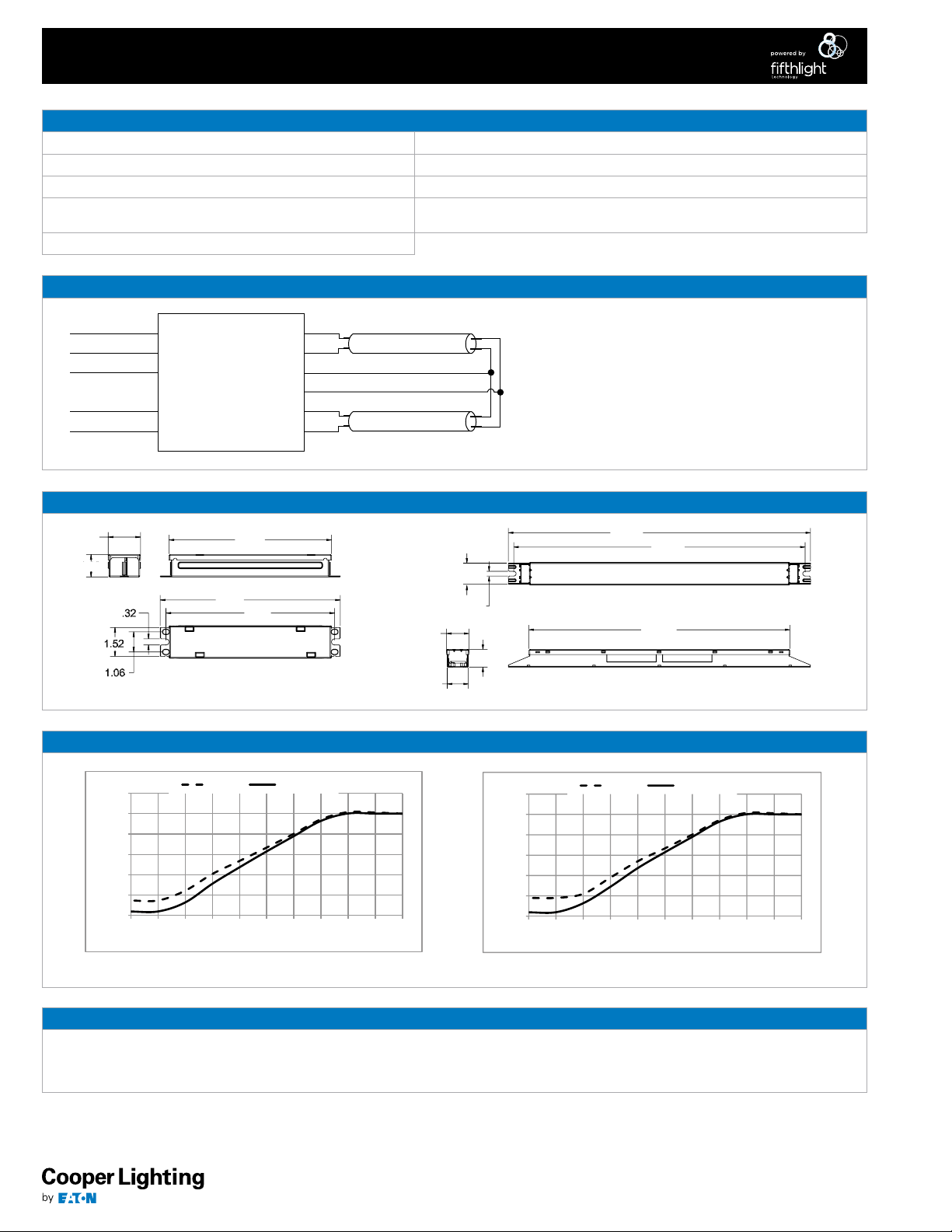
Use Purple (+) and Gray (-) for connection to 0-10VDC 0V = Minimum Light Output
Wiring Purple and Gray together provides 3% light output Can be wired Class I or Class II
Capping Purple and Gray separately provides 100% light output Ballast will source a maximum of 250µA for control needs
Built-in line voltage protection: Minimum Light Output level will occur
if line voltage is applied
10VDC = Maximum Light Output
WIRING DIAGRAM
0-10V Dimming Ballast Specifications
Control must be capable of sinking current supplied by ballast
Green (ground)
White (neutral)
Black (line)
Purple (control +)
Gray (control -)
BALLAST DRAWINGS
1.18
DIMMING CURVES
Ballast
8.58
9.50
8.90
‘A’ BALLAST
Red
Red
Blue
Blue
Yellow
Yellow
1.25
1.18
16.28
1.18
.26
14.58
1.00
‘D’ BALLAST
120%
100%
80%
60%
40%
20%
0%
12345678910 11
Power Light Output
Control Voltage (VDC)
T5 Dimming Curve
120%
100%
80%
60%
40%
20%
0%
012345678910
Power Light Output
Control Voltage (VDC)
T8 Dimming Curve
WARRANTY AND SUPPORT INFORMATION
Cooper Lighting warrants to the purchaser that each factory-installed electronic ballast will be free from defects in material or workmanship for a
period of five (5) years from the date of manufacture when properly installed and under normal conditions of use.
Call (800) 955-4946 or email [email protected] for warranty information and support.
Eaton
1000 Eaton Boulevard
Cleveland, OH 44122
United States
Eaton.com
Eaton’s Cooper Lighting Business
1121 Highway 74 South
Peachtree City, GA 30269
P: 770-486-4800
www.cooperlighting.com
Specifications and
dimensions subject to
change without notice.
ACF130940 8/5/14
 Loading...