

Page 1
ENGLISH
ESPAÑOL
FRANÇAIS
MS180, CMS180
MS180W, CMS180W
Instruction Manual
Instrucciones
Directives
MS180_W 825-0216.qxd:MS180 325-1553.qxd 6/26/08 2:57 PM Page 1
Page 2
MS180, CMS180 (Bronze)
MS180W, CMS180W (White)
ENGLISH
2
Call for customer service and/or missing or damaged parts (800-334-6871)
Congratulations! You have purchased a Cooper Lighting, LLC motion activated
detector for outdoor lighting. When installed properly, this sensor will provide
years of convenience and protection for your home and family.
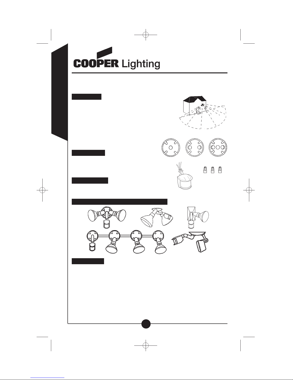
How it works
Your motion activated detector senses heat
from objects such as people, large animals and
automobile engines. When motion is detected, the
lights connected to the detector will automatically
turn on. Once motion has stopped, the lights will
automatically turn off after a preselected
time delay. With your motion activated
detector attached, you may also control
your lights manually from the wall switch.
What you need
• Phillips screwdriver
• Outdoor weatherproof silicone caulking
• 1, 2, or 3-hole junction box coverplate (A)
What’s included
• Motion detector (B)
• (3) Wire nuts (C)
Common wall and eave mounting applications
What to know
• cULus Listed for wet location use.
• This device complies with Part 15 of the FCC Rules. Operation is subject to
the following two conditions: (1) This device may not cause harmful
interference, and (2) this device must accept any interference received,
including interference that may cause undesired operation. Under Part 15 of
the FCC Rules, any changes or modifications to the motion detector
described in this instruction sheet that are not expressly approved by Cooper
Lighting, LLC could void the user!s authority to operate the equipment.
70
feet
180 degrees
A
B
C
MS180_W 825-0216.qxd:MS180 325-1553.qxd 6/26/08 2:58 PM Page 2
Page 3
ENGLISH
3
Call for customer service and/or missing or damaged parts (800-334-6871)
Note: This equipment has been tested and found to comply with the limits for
a Class B digital device, pursuant to part 15 of the FCC Rules. These limits are
designed to provide reasonable protection against harmful interference in a
residential installation. This equipment generates, uses and can radiate radio
frequency energy and, if not installed and used in accordance with the
instructions, may cause harmful interference to radio communications.
However, there is no guarantee that interference will not occur in a particular
installation. If this equipment does cause harmful interference to radio or
television reception, which can be determined by turning the equipment off and
on, the user is encouraged to try to correct the interference by one or more of
the following measures:
• Reorient or relocate the receiving antenna.
• Increase the separation between the equipment and receiver.
• Connect the equipment into an outlet on a circuit different from that to
which the receiver is connected.
• Consult the dealer or an experienced radio/TV technician for help.
• Fixture must be connected to a 120 Volt, 60 Hz power source. Any other
connection voids warranty.
• Total wattage of light bulbs connected to the motion detector cannot exceed
500 watts incandescent / tungsten / halogen.
• This motion detector should be installed by persons with experience in
household wiring or by a qualified electrician. The electrical system, and the
method of electrically connecting the fixture to it, must be in accordance with
the National Electrical Code and local building codes.
• For supply connections, use wire rated at least 90˚C.
• For proper operation and protection against damage, the motion detector
head adjustment knobs must be facing the ground.
• Disassembly of your fixture will void the warranty.
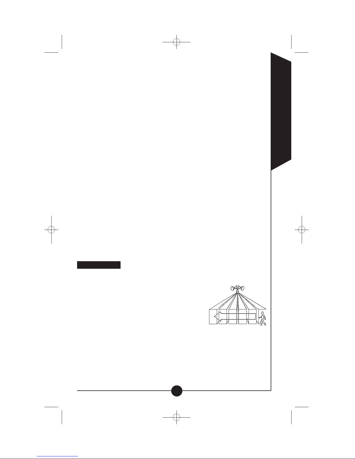
For best results
• Install your fixture 8-12 feet above ground (motion
detector is less sensitive above 12 feet).
• Locate fixture so motion moves across detection
zone (Fig.1).
• Locate fixture away from heat producing sources
to prevent false triggering. Also be very careful
not to include objects such as windows, white
walls and water in the detection zone whenever
possible.
• Locate fixture away from moving objects such as trees and street traffic.
• Do not install more than one motion detector on one wall switch.
Fig. 1
MS180_W 825-0216.qxd:MS180 325-1553.qxd 6/26/08 2:58 PM Page 3
Page 4

ENGLISH
Assembling and wiring your motion detector
Step 1: Turn off the power at the main fuse/breaker box. Check to make sure
power has been disconnected before continuing.
Step 2: Screw motion detector arm into the desired
hole on junction box coverplate.
Step 3: Attach all lampholders or light fixtures
to the coverplate as required by light
fixture instructions.
Step 4: Connect the wires together. Connect all
white wires together (house wire, detector
wire, and lamp fixture white wires) using
wire nuts provided. Connect black lamp
wires to red wire from the detector.
Connect black house wire to black wire
from the detector (Fig. 2).
Step 5: Attach fixture to the junction box according
to light fixture instructions.
Step 6: Apply silicone caulking around the edges of coverplate
and in any open screw holes for a watertight seal.
Step 7: Insert bulb(s) according to light fixture instructions.
Step 8: Turn power on at main fuse/breaker box.
How to operate your fixture
Step 1: Move slide switch on bottom of the sensor to
“TEST”. Set sensitivity knob to medium
(halfway) (Fig. 3).
Step 2: Turn on the power to fixture. Allow fixture to
warm up approximately 40 seconds before
testing. (Lights will come on and stay on
during warm-up period.)
Step 3: Aim sensor head toward desired detection area, maintaining a 15°
down angle to allow moisture to drain.
Note: Maintain air spacing between lamps and sensor head, at least 1˝.
Make sure sensor head is positioned with control switches facing towards
the ground.
Step 4: Walk across the detection zone at the farthest distance you wish your
detector to detect motion.
Step 5: Adjust sensitivity until you get desired results. Lights will turn off 4
seconds after all motion stops.
Step 6: Move slide switch to 4 MIN or 12 MIN (AUTO mode). At dusk, lights
will operate in the AUTO setting.
Your fixture mounts to
the following standard
junction boxes:
Fig. 3
Fig. 2
Call for customer service and/or missing or damaged parts (800-334-6871)
4
round octogonal
MS180_W 825-0216.qxd:MS180 325-1553.qxd 6/26/08 2:58 PM Page 4
Page 5
ENGLISH
5
Call for customer service and/or missing or damaged parts (800-334-6871)
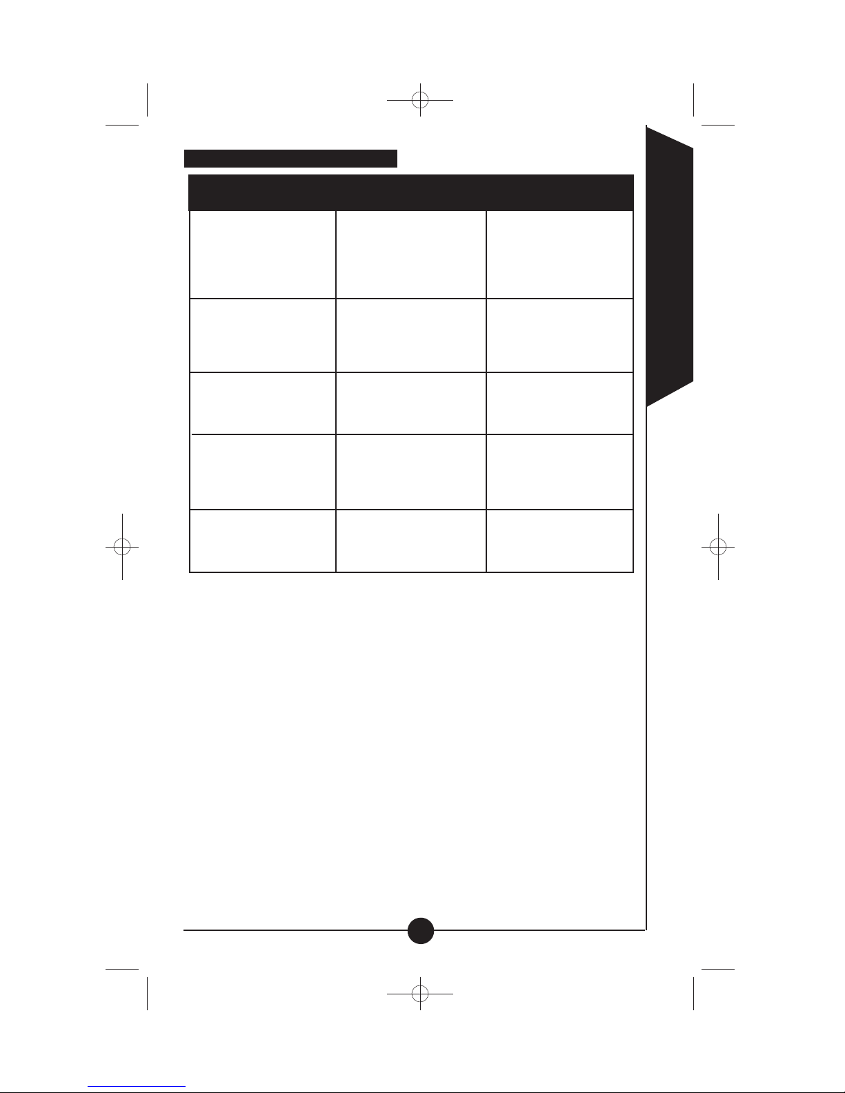
How to select your desired feature
What to do if...
Auto setting
(motion activated)
Lights should turn on with
motion only at night and
should turn off after
4 or 12 minutes.
4 MIN
or
12 MIN
Keep the power to
the fixture on.
Dusk to Dawn Setting
(activated only at night)
Lights should stay on from
dusk to dawn and then reset
to the auto setting next dawn.
Turn power on and off twice
within 3 seconds
Mode of
operation:
Set slide switch
on sensor to:
How to set
power switch:
4 MIN
or
12 MIN
Standard Floodlight Setting
Lights should stay on continu-
ously both day and night
(must be reset manually).
TEST Turn power on and off twice
within 3 seconds
Test Setting
Lights should turn on with
motion both day and night.
Lights should turn off after
4 seconds.
TEST
Turn the power to the
fixture on.
Return to Auto Setting
(motion activated)
From any of the above
setting.
4 MIN
or
12 MIN
Turn the power “OFF” for at
least 40 seconds, then
back “ON”.
MS180_W 825-0216.qxd:MS180 325-1553.qxd 6/26/08 2:58 PM Page 5
Page 6
ENGLISH
6
Call for customer service and/or missing or damaged parts (800-334-6871)
FPO:
Image Copy for Tags
Is there power to the fixture?
• Check to see that the circuit breaker has not been tripped.
• Be sure the wall switch is in the “ON” position.
• Be sure that the bulb is not burned out or broken.
Is the surrounding external ambient light too bright? (If so
the unit may think it!s daytime.)
• Re-aim the head.
• Relocate or reposition the unit away from the light.
TURN OFF POWER BEFORE CONTINUING.
Is the wiring to the fixture loose?
• Check wiring, and reconnect if necessary using wire
nuts provided.
Outdoor lights do not come
on with motion at night
Is there motion in the detection zone?
• Make sure the sensor is not picking up moving objects such
as trees, traffic, etc.
TEST FOR YOURSELF.
• Cover the sensor lens with cardboard to prevent
sensor from detecting motion. If the lights stay off, some
thing in the detection zone is triggering the sensor.
• If this is the case, reduce the sensitivity.
• Reposition motion sensor.
*If the lights stay on with sensor lens covered, contact customer service.
Outdoor lights come on for
no apparent reason at night
Is there motion in the detection zone?
• Make sure the sensor is not picking up moving objects such
as trees, traffic, etc.
• If this is the case, reduce the sensitivity.
• Reposition motion sensor.
If there is no motion, then the unit may be in the override
mode.
• Turn the light switch to the “OFF” position for 40
seconds, and then back to the “ON” position. This will send
the unit back into the AUTO mode.
*If the lights continue to stay on, contact customer service.
Lights stay on at night and do
not turn off
The light given off from the unit!s own lamp(s) is affecting the
motion sensor.
• Re-aim lamp(s).
• Reposition motion sensor.
Lights continuously blink on
and off at night
Is the switch on the bottom of the motion sensor in the test
mode?
• Move the switch to the 4 MIN or 12 MIN position.
Is the motion detector shadowed?
• Reposition motion sensor.
Lights are on
during the day
Is the surrounding external ambient light too bright? (If so the
unit may think it!s daytime.)
• Re-aim the head.
• Relocate or reposition the unit away from the light.
Are you allowing adequate time to enter the dusk to dawn
mode?
• Turn power on and off twice within 3 seconds.
Is there more than one fixture on an indoor wall switch?
• If so, put them on separate switches.
Cannot activate dusk to dawn
mode at night (override)
What to do if. ..
MS180_W 825-0216.qxd:MS180 325-1553.qxd 6/26/08 2:58 PM Page 6
Page 7

ENGLISH
7
Two-year limited warranty
Cooper Lighting, LLC (“the Company”) warrants this product (“the product”) against
defects in material or workmanship for a period of two years from date of original
purchase, and agrees to repair or, at the Company!s option, replace a defective
product without charge for either replacement parts or labor during such time. This
does not include labor to remove or install fixtures.
This warranty is extended only to the original purchaser of the product. A purchasers receipt or other proof of date of original purchase acceptable to the
Company is required before warranty performance shall be rendered.
This warranty only covers product failure due to defects in materials or workmanship which occurs in normal use. It does not cover the bulb or failure of the product caused by accident, misuse, abuse, lack of reasonable care, alteration, or
faulty installation, subjecting the product to any but the specified electrical service
or any other failure not resulting from defects in materials or workmanship.
Damage to the product caused by separately purchased, non-Company brand
replacement bulbs and corrosion or discoloration of brass components are not covered by this warranty.
There are no express warranties except as described above. THE COMPANY
SHALL NOT BE LIABLE FOR INCIDENTAL, SPECIAL OR CONSEQUENTIAL
DAMAGES RESULTING FROM THE USE OF THE PRODUCT OR ARISING OUT
OF ANY BREACH OF THIS WARRANTY. ALL IMPLIED WARRANTIES, IF ANY,
INCLUDING IMPLIED WARRANTIES OF MERCHANTABILITY AND FITNESS
FOR A PARTICULAR PURPOSE, ARE LIMITED IN DURATION TO THE DURATION OF THIS EXPRESS WARRANTY.
Some states do not allow the exclusion or limitation of incidental or consequential
damages, or limitations on how long an implied warranty lasts, so the above exclusions or limitations may not apply to you.
No other warranty, written or verbal, is authorized by the Company. This warranty
gives you specific legal rights, and you may also have other rights which vary from
state to state.
To obtain warranty service, please write to: Cooper Lighting, LLC, 1121 Highway
74 South, Peachtree City, GA 30269. Enclose product model number and problems you are experiencing, along with your address and telephone number. You
will then be contacted with a solution, or a Return Goods Authorization number and
full instructions for returning the product. All returned products must be accompanied by a Return Goods Authorization Number issued by the Company and must
be returned freight prepaid. Any product received without a Return Goods
Authorization Number from the Company will be refused.
Cooper Lighting, LLC is not responsible for merchandise damaged in transit.
Repaired or replaced products shall be subject to the terms of this warranty and are
inspected when packed. Evident or concealed damage that is made in transit should
be reported at once to the carrier making the delivery and a claim filed with them.
Customer First Center
1121 Highway 74 South, Peachtree City, GA 30269
www.cooperlighting.com
Patents 6,326,622, D428,352,5,381,323
© 2008 Cooper Lighting, LLC
Reproductions of this document without prior written approval of Cooper Lighting, LLC
are strictly prohibited.
Call for customer service and/or missing or damaged parts (800-334-6871)
Printed in China
MS180_W 825-0216.qxd:MS180 325-1553.qxd 6/26/08 2:58 PM Page 7
Page 8

MS180, CMS180 (Bronce)
MS180W, CMS180W (Blanco)
ESPAÑOL
8
Felicitaciones. Usted ha comprado un detector activado por movimiento
Cooper Lighting, LLC para iluminación exterior. Cuando se instala debidamente, este sensor proporciona muchos años de conveniencia y protección
para su hogar y su familia.
Cómo funciona
Su detector activado por movimiento detecta
imágenes térmicas de tales objetos como personas,
animales grandes y motores de automóvil. Cuando
se detecta movimiento, las lámparas conectadas al
detector se encenderán automáticamente. Una vez
que haya parado el movimiento, las lámparas se
apagarán automáticamente después de
un retardo de tiempo preseleccionado.
Con su detector activado por movimiento
conectado, también puede controlar las
lámparas manualmente con el interruptor
de pared.
Qué se requiere
• Destornillador phillips
• Calafateo impermeable
• Placa de cierre de la caja de conexiones
de 1, 2 ó 3 agujeros (A)
Qué se incluye
• Detector de movimiento (B)
• (3) Tuercas para alambres
Aplicaciones de montaje para paredes y aleros comunes
Que se necesita saber
• Aprobado por cULus para su utilización en áreas mojadas.
70 pies
/
21 m
180 grados
A
B
C
Llame para obtener servicio al cliente y/o piezas faltantes o dañadas (800-334-6871)
MS180_W 825-0216.qxd:MS180 325-1553.qxd 6/26/08 2:58 PM Page 8
Page 9

ESPAÑOL
9
• Este dispositivo cumple con la parte 15 de las reglas de la FCC. Su
funcionamiento está sujeto a las dos condiciones siguientes: (1) Este
dispositivo no debe causar interferencia dañina, y (2) este dispositivo debe
aceptar cualquier interferencia recibida, incluida la que pueda causar
funcionamiento indeseado. Según lo estipulado en la Parte 15 de las
reglas de FCC, cualquier cambio o modificación hecha al detector de
movimiento descrito en esta hoja de instrucciones que no esté expresamente
aprobado por Cooper Lighting podría anular la autorización otorgada al
usuario para utilizar este equipo.
Nota: Este equipo fue probado en servicio y encontrado de conformidad con
los límites para un dispositivo digital Clase B, de acuerdo a lo estipulado en la
Parte 15 de las reglas de FCC. Estos límites tienen como fin proporcionar
protección razonable contra la interferencia perjudicial en una instalación
residencial. Este equipo genera, utiliza y puede irradiar energía de
radiofrecuencia, y si no se instala y usa de acuerdo con las instrucciones,
puede causar interferencia perjudicial para las radiocomunicaciones. Sin
embargo, no existe ninguna garantía de que no ocurrirá interferencia en una
instalación en particular. Si este equipo llegara a causar interferencia
perjudicial para la recepción de radio o de televisión, lo que puede
determinarse encendiendo y apagando el equipo, se recomienda al usuario
tratar de corregir la interferencia tomando una o más de las medi
das siguientes:
• Cambie la orientación o ubicación de la antena receptora.
• Aumente la separación entre el equipo y el receptor.
• Conecte el equipo a un tomacorriente en un circuito diferente de aquel al
cual está conectado el receptor.
• Consulte con el concesionario o un técnico en radio/televisión competente.
• El portalámparas se debe conectar a una fuente de energía de 60 Hz,
120 Voltios. Cualquier otro tipo de conexión anula la garantía.
• El vatiaje total de los focos de luz conectadas al sensor de movimiento no
puede exceder una incandescencia / tungsteno / halógena de 500 watts.
• El portalámparas debe ser instalado por personas con experiencia en
cableado doméstico opor un electricista calificado. El sistema eléctrico y el
método utilizado para la conexión eléctrica de este portalámparas al mismo
debe regirse por el Código Eléctrico Nacional y por los códigos locales de
construcción.
• Para empalmes de alimentación utilize un cableado de temperatura nominal
de al menos 90˚C.
• Para el funcionamiento debido y protección contra daños, los pomos de
ajuste de la cabeza del detector de movimiento deben estar orientados hacia
el suelo.
• Si por alguna razón se desarma el portalámparas, la garantía quedará
automáticamente eliminada.
Llame para obtener servicio al cliente y/o piezas faltantes o dañadas (800-334-6871)
MS180_W 825-0216.qxd:MS180 325-1553.qxd 6/26/08 2:58 PM Page 9
Page 10

Para obtener mejores resultados
• Instale su portalámparas a 8-12 pies (2.4 – 3.7 m)
del piso. El detector de movimiento es menos
sensible si se encuentra a una altura superior a
los 12 pies (3.7 m).
• Coloque el portalámparas de manera que se
mueva por toda la zona de detección (Fig. 1).
• Coloque el portalámparas lejos de fuentes de calor para prevenir una falsa
activación. Siempre que sea posible trate de no introducir en el área de
detección objetos tales como cale factores, aparatos de aire acondicionado,
respiraderos de lavaderos y superficies reflectantes tales como ventanas,
paredes blancas y agua.
• Coloque el portalámparas lejos de objetos en movimiento tales como árboles
y tráfico callejero.
• No instale más de una lámpara de alta intensidad activada por movimiento
en un interruptor de pared.
Ensamblando y cableando su detector de movimiento
Paso 1: Desactive la fuente de alimentación en la caja de fusibles/
interruptor automático principal. Revisar para asegurarse
que la corriente haya sido desconecta
da antes de continuar.
Paso 2: Atornille el brazo del detector de
movimiento en el agujero deseado en la
placa de cierre de la caja de conexiones.
Paso 3: Sujete todos los portalámparas a la placa
de cierre según sea requerido por las
instrucciones del portalámparas.
Paso 4: Conecte los cables juntos. Conecte
todos los cables blancos juntos (cable
blanco de la casa, cable blanco del
detector y cable blanco del portalám
paras) usando las tuercas suministradas.
Conecte los cables negros de la lámpara
al cable rojo del detector. Conecte el
cable negro de la casa al cable negro del
detector (Fig. 2).
Paso 5: Conecte el portalámparas a la caja de conexiones de acuerdo con
las instrucciones del portalámparas.
Paso 6: Aplique calafateo de silicona alrededor de los bordes de la placa
de la cubierta y en cualquier agujero para tornillos que se
encuentre abierto.
Paso 7: Introduzca el foco con las instruciones del potalámparas.
Paso 8: Active la fuente de alimentación en la caja de fusibles/
interruptor automático.
ESPAÑOL
10
Llame para obtener servicio al cliente y/o piezas faltantes o dañadas (800-334-6871)
Fig. 1
Su portalámparas se
ajusta a estas cajas de
empalmes:
Fig. 2
redonda octagonal
MS180_W 825-0216.qxd:MS180 325-1553.qxd 6/26/08 2:58 PM Page 10
Page 11

ESPAÑOL
11
Operación de su portalámparas
Paso 1: Mueva el interruptor corredizo que se
encuentra en la parte inferior del sensor a
“TEST”. Ajuste el botón de sensibili
dad a la posición media (hasta la mitad)
(Fig 3.).
Paso 2: Active la energía del portalámparas.
Deje que el portalámparas se caliente
aproximadamente 40 segundos antes de hacer las pruebas.
(Las luces se encenderán y permancerán encendidas durante el
período de calentamiento.)
Paso 3: Dirija la cabeza del sensor hacia el área de detección deseada,
manteniendo un ángulo de 15° hacia abajo, para permitir el drenaje
de la humedad.
Nota: Deje un espacio de aire de por lo menos 1˝ (25.4 mm) entre las lámparas y el sensor. Asegúrese de que la cabeza del sensor esté colocada con
los interruptores de control en dirección al piso.
Paso 4: Camine a través de la zone de detección tan lejos como desee que
su detector registre movimiento.
Paso 5: Ajuste el grado de sensibilidad hasta que obtenga los resultados
deseados. Las luces se apagarán 4 segundos después de que todo
movimiento se ha detenido.
Paso 6: Mueva el interruptor corredizo a 4 MIN o 12 MIN (AUTO moda).
Al anochecer, las luces funcionarán en el modo AUTOMATICO.
Llame para obtener servicio al cliente y/o piezas faltantes o dañadas (800-334-6871)
Fig 3
MS180_W 825-0216.qxd:MS180 325-1553.qxd 6/26/08 2:58 PM Page 11
Page 12

12
ESPAÑOL
Ajuste Automático
(activado por movimiento)
Las luces deben encenderse
por el movimiento sólo
durante la noche y deben
apagarse después de
4 ó 12 minutos.
4 MIN
o
12 MIN
Mantenga la limentación del
portalámparas activada.
Ajuste Amanecer-Atardecer
(activado sólo durante
la noche)
Las luces deben permanecer
encendidas desde el atardecer
hasta el amanecer y luego
restituirse a la posición de
ajuste automático al amanecer
siguiente.
Encienda y apague la
alimentación eléctrica
dos veces en un período de
3 segundos
Funcionamiento
deseado:
Coloque el interruptor
corredizo en:
Como ajustar
interruptor electrico:
4 MIN
o
12 MIN
Ajuste Estándar de Una
Lámpara de Alta Intensidad
Las luces deben permanecer
encendidas continuamente,
durante el día y la noche
(se debe ajustar a mano).
TEST Encienda y apague la
alimentación eléctrica dos
veces en un período
de 3 segundos
Ajuste de Prueba
Las luces deben encenderse
por el movimiento tanto en el
día como en la noche. Las
luces deben apagarse
después de 4 segundos.
TEST
Mantenga la alimentación del
portalámparas activada.
Reajuste el Portalámparas a
Ajuste Automático
(activado por movimiento)
Desde cualquier posición.
4 MIN
o
12 MIN
DESACTIVE la alimentación
40 segundos, luego vuélvala
a ACTIVAR.
Cómo seleccionar la característica deseada
Llame para obtener servicio al cliente y/o piezas faltantes o dañadas (800-334-6871)
MS180_W 825-0216.qxd:MS180 325-1553.qxd 6/26/08 2:58 PM Page 12
Page 13

ESPAÑOL
13
Llame para obtener servicio al cliente y/o piezas faltantes o dañadas (800-334-6871)
FPO:
Image Copy for Tags
¿Está llegando corriente a la unidad?
• Compruebe que el interruptor automático no haya saltado.
• Asegúrese de que el interruptor de la pared está en la posición “ON”.
• Asegúrese de que el foco no se haya quemado o roto.
¿Es la luz ambiental externa demasiado intensa? (Si es así la unidad
actuará como si fuera de día.)
• Redirija el cabezal.
• Cambie la ubicación de la unidad o diríjala en dirección
contraria a la luz.
DESCONECTE LA ENERGÍA ANTES DE CONTINUAR.
¿Están sueltos los cables del aparato?
• Revise los cables y vuélvalos a conectar si fuera necesario usando
las tuercas que se incluyen.
¿Existe movimiento en el área de detección?
• Asegúrese de que el sensor no esté reaccionando a obje tos móviles
tales como árboles, tráfico, etc.
COMPRUÉBELO USTED MISMO.
• Cubra la lente del sensor con un trozo de cartón para evitar que detecte
movimiento. Si las luces permanecen apa gadas, hay algo en el área
de detección que está activando el sensor.
• Si este es el caso, disminuya la sensibilidad.
• Cambie la posición del sensor de movimiento.
*Si las luces permanecen encendidas con la lente del sensor cubierta,
póngase en contacto con el servicio de asistencia al cliente.
¿Existe movimiento en el área de detección?
• Asegúrese de que el sensor no esté reaccionando a obje tos móviles
tales como árboles, tráfico, etc.
• Si este es el caso, disminuya la sensibilidad.
• Cambie la posición del sensor de movimiento.
Si no hay movimiento, la unidad puede estar en la modalidad de anlación.
• Ponga el interruptor de la luz en “OFF” durante 40 segundos y vuel
va a colocarlo en “ON”. Esto colocará de nuevo la unidad en la
modalidad AUTO.
*Si las luces permanecen encendidas con la lente del sensor
cubierta, póngase en contacto con el servicio de asistencia al cliente.
La luz proveniente de la propia lámpara de la unidad está afectando al
sensor de movimiento.
• Cambie la dirección de la(s) lámpara(s).
• Cambie la posición del sensor de movimiento.
¿Está el interruptor que se encuentra en la parte inferior del sensor de
movimiento en la modalidad de prueba?
• Coloque el interruptor en la modalidad 4 MIN ó 12 MIN.
¿Algo está dando sombra sobre el detector de movimiento?
• Cambie la posición del sensor de movimiento.
¿Es la luz ambiental externa demasiado intensa? (Si es así la unidad
actuará como si fuera de día.)
• Redirija el cabezal.
• Cambie la ubicación de la unidad o diríjala en dirección contraria a la luz.
¿Está usted dejando suficiente tiempo para que pueda entrar en la modalidad
de “Atardecer-Amanecer”?
• Encienda y apague la alimentación eléctrica dos veces en un período
de 3 segundos
¿Hay más de un aparato conectado en un interruptor de pared de la casa?
• Si es así, conéctelos en interruptores diferentes.
Las luces
exteriores no se
encienden durante
la noche aunque
haya movimiento
Las luces
exteriores se
enciended durante
la noche sin
motivo aparente
Las luces se
encienden durante
la noche y no se
apagan
Las luces se
encienden y
se apagan
continuamente
uamente durante
la noche
Las luces se
enciendedn
durante el dia
No se puede
activar la modalidad de “AtardecerAmanecer”
durante la noche
(encendido)
Que hacer si...
MS180_W 825-0216.qxd:MS180 325-1553.qxd 6/26/08 2:58 PM Page 13
Page 14

ESPAÑOL
14
Dos años de garantía limitada
Cooper Lighting, LLC ("la Compañía!) garantiza este producto ("el producto!)
contra defectos de material o fabricación, por un período de dos años a partir
de la fecha de la compra original, y acuerda reparar o, a opción de la
Compañía, reemplazar un producto defectuoso sin cargo, ya sea por las piezas
de reemplazo o la mano de obra correspondiente, durante dicho tiempo. Esto
no incluye la mano de obra necesaria para retirar o instalar artefactos.
Esta garantía se extiende únicamente al comprador original del producto.
Antes de efectivizar el cumplimiento de la garantía, se requiere del comprador
un recibo u otra prueba de la fecha de la compra original, que sea aceptable
para la Compañía.T
Esta garantía cubre únicamente las fallas del producto debidas a defectos en
sus materiales o fabricación, que ocurran durante su uso normal. No cubre la
lámpara, ni las fallas del producto causadas por accidente, mal uso, maltrato,
falta de cuidado razonable, alteración o instalación defectuosa, conexión del
producto a un suministro eléctrico distinto del especificado, o cualquier otra falla
que no sea consecuencia de defectos en los materiales o en la fabricación.
Los daños causados al producto por lámparas de repuesto adquiridas
separadamente, que no sean de la marca de la Compañía, y por corrosión
o decoloración de los componentes de latón, no están cubiertos por esta
garantía.
No existen otras garantías expresas más que la descripta anteriormente.
LA COMPAÑIA NO SERA RESPONSABLE DE DAÑOS INCIDENTALES,
ESPECIALES O CONSIGUIENTES QUE RESULTEN DEL USO DEL PRODUCTO O SE ORIGINEN EN CUALQUIER INFRACCION A ESTA GARANTIA.
TODA GARANTIA IMPLICITA, SI LA HUBIERA, INCLUYENDO GARANTIAS
IMPLICITAS DE COMERCIABILIDAD Y ADECUACION PARA UN FIN
PARTICULAR, ESTAN LIMITADAS EN DURACION A LA DURACION DE ESTA
GARANTIA EXPRESA. Algunas jurisdicciones o estados no permiten la
exclusión o limitación de daños incidentales o consiguientes, o las limitaciones
sobre la duración de una garantía implícita, de modo que las exclusiones o
limitaciones indicadas pueden no ser aplicables a su caso.
La Compañía no autoriza ninguna otra garantía, ya sea escrita o verbal.
Esta garantía le otorga derechos legales específicos, y es posible que usted
tenga otros derechos, que pueden variar de una jurisdicción o estado, a otro.
Para obtener servicio en garantía escriba a Cooper Lighting, LLC, 1121 Highway
74 South, Peachtree City, GA 30269, Estados Unidos de América. Indique el
número de modelo del producto y los problemas que experimenta, además de
su dirección y número de teléfono. Será contactado entonces para obtener una
solución, o un número de Autorización de Retorno de Mercancías ("Return
Goods Authorization!) e instrucciones completas para regresar el producto.
Todos los productos que se regresen deben estar acompañados por el Número
de Autorización de Retorno de Mercancías emitido por la Compañía, y deben
regresarse con el flete previamente pagado. Todo producto que se reciba
sin el Número de Autorización de Retorno de Mercancías emitido por la
Compañía, será rechazado.
Llame para obtener servicio al cliente y/o piezas faltantes o dañadas (800-334-6871)
MS180_W 825-0216.qxd:MS180 325-1553.qxd 6/26/08 2:58 PM Page 14
Page 15

ESPAÑOL
15
Cooper Lighting, LLC no se hace responsable por los daños que puedan
experimentar las mercancías en tránsito. Los productos reparados o reemplazados estarán sujetos a los términos de esta garantía, y se inspeccionan al
embalarlos. Ante cualquier daño evidente u oculto ocurrido en tránsito, debe
informarse enseguida al transportista que realiza la entrega, y presentarle el
correspondiente reclamo.
Customer First Center
1121 Highway 74 South, Peachtree City, GA 30269
www.cooperlighting.com
Patentes 6,326,622, D428,352,5,381,323
© 2008 Cooper Lighting, LLC
La reproducción de este documento sin la aprobación previa por escrito de
Cooper Lighting, LLC está estrictamente prohibida.
Llame para obtener servicio al cliente y/o piezas faltantes o dañadas (800-334-6871)
Impreso en China
MS180_W 825-0216.qxd:MS180 325-1553.qxd 6/26/08 2:58 PM Page 15
Page 16

MS180, CMS180 (Bronze)
MS180W, CMS180W (Blanc)
FRANÇAIS
16
Pour le service à la clientèle et ou pour des pièces manquantes ou endommagées, appeler au 800-334-6871
Félicitations. Vous avez acheté un détecteur déclenché par mouvement pour
éclairage extérieur Cooper lighting, LLC. Quand il est bien monté, ce détecteur
fournira des années d!utilisation pratique et de protection pour votre maison et
pour votre f
Comment votre projecteur fonctionne
Votre détecteur déclenché par mouvement détecte
l!image thermique de personnes, de gros animaux et
de moteurs de voitures. Quand un mouvement est
détecté, les lumières branchées sur le détecteur
s!allument automatiquement. Dès que le mouvement
cesse, les lumières s'éteignent automatiquement après un délai choisi au préalable. Une fois que votre détecteur
déclenché par mouvement est fixé, vous
pouvez aussi commander les lumières
manuellement àpartir de l!interrupteur mural.
Ce dont vous avez besoin
• Tournevis phillips
• Produit de calfatage résistant aux intempéries
• Couvercle de boîte de jonction à 1, 2 ou 3 trous (A)
Ce qui est compris dans cet ensemble
• Détecteur de mouvement (B)
• (3) Ecrous pour fil (C)
Applications de montage communes pour mur et avant-toit
Ce qu’il faut savoir
• Homologués cULus pour les endroits humides.
• Cet appareil est conforme à la partie 15 des règles FCC. Son fonctionnement
est sujet à deux conditions : (1) Cet appareil ne crée pas d!interférences
nuisibles et (2) cet appareil doit accepter les interférences reçues, y com pris
les interférences qui pourraient entraîner un fonctionnement indésirable.
180 degrés
B
C
A
70
pied /
21
m
MS180_W 825-0216.qxd:MS180 325-1553.qxd 6/26/08 2:58 PM Page 16
Page 17

FRANÇAIS
17
Pour le service à la clientèle et ou pour des pièces manquantes ou endommagées, appeler au 800-334-6871
Conformément aux dispositions de la partie 15 des règles de la FCC, toute
modification apportée au détecteur de mouvement décrit dans ce feuillet
d!instructions, sans l!approbation expresse de Cooper Lighting, pourrait
annuler l!autorisation d!utilisation de cet équipement accordée à l!acheteur.
Remarque : Cet équipement a été testé et s!est avéré conforme aux limites
s!appliquant aux appareils numériques de classe B, conformément aux dispo
sitions de la partie 15 des règles de la FCC. Ces limites sont conçues pour
offrir une protection raisonnable contre les interférences nuisibles dans une
installation résidentielle. Cet équipement produit, utilise et peut émettre de
l!énergie en fréquence radio. S!il n!est pas installé et utilisé conformément aux
instructions, il peut provoquer des interférences nuisibles aux communications
radio. Cependant, il n!existe aucune garantie qu!une installation quelconque
ne produira pas d!interférence. Si cet équipement cause des interférences
nuisant au fonctionnement d!un appareil radio ou d!un téléviseur (ce qui peut
être déterminé en activant/désactivant l!équipement), l!utilisateur est encour
agé à éliminer les interférences en appliquant l!une des mesures suivantes :
• Réorientez ou déplacez l!antenne réceptrice.
• Augmentez l!espace entre l'équipement et le poste récepteur.
• Branchez l!équipement sur une prise ou un circuit ne servant pas au
poste récepteur.
• Demandez l!aide de votre marchand ou d!un technicien expérimenté en
radio/télévision.
• La pièce fixe doit être branchée à une source d!énergie de 120 Volts /
60 Hertz. Tout autre branchement que celui-ci annule la garantie.
• Le total wattage des ampoules branchées sur le détecteur de mouvement ne
doit pas dépasser / tungstène / halogène 500 watts.
• Ce détecteur doit être installé par une personne familière avec l!installation
électrique de la maison ou par un électricien qualifié. Le système électrique
et la méthode du branchement du dispositif à cette installation électrique
doivent respecter les spécifications du Code électrique national ainsi que les
réglementations locales pour le bâtiment.
• Pour raccordements d!alimentation, utiliser du câblage à température
nominale d!au moins 90°C.
• Pour éviter les dommages et obtenir un fonctionnement correct, la tête du
détecteur doit faire face au sol.
• Le démontage de cet ensemble annulera la garantie.
Pour de meilleurs résultats
• Installez le dispositif à 8-12 pieds (2.4 – 3.7 m)
au-dessus du sol. Le détecteur de mouvement
est moins sensible au-dessus de 12 pieds (3.7 m).
• Placez le dispositif de manière qu!une
personne puisse se déplacer à travers la zone
de détection (Sch. 1).
Sch. 1
MS180_W 825-0216.qxd:MS180 325-1553.qxd 6/26/08 2:58 PM Page 17
Page 18

FRANÇAIS
18
Pour le service à la clientèle et ou pour des pièces manquantes ou endommagées, appeler au 800-334-6871
• Placez le dispositif loin de toute source de chaleur afin qu!il ne se déclenche
pas par erreur. Si possible, prenez également soin de ne pas mettre dans la
zone de détection des objets tels que des pompes à chaleur, des climatiseurs,
des conduits pour sèche-linge et des surfaces réfléchissantes comme des
fenêtres, des murs blancs et de l!eau.
• Placez le dispositif loin de tout objet en mouvement tel que des arbres et la
circulation dans la rue.
• Ne pas monter plus d!un éclairage déclenché par mouvement sur un seul
interrupteur mural.
Montage et câblage du détecteur de mouvement
Étape 1 : Coupez l!électricité au disjoncteur
principal. Assurez-vous que
l!alimentation électrique soit
débranchée avant de continuer.
Étape 2 : Visser le bras du détecteur de
mouvement dans le trou désiré sur le
couvercle de la boite de jonction.
Étape 3 : Fixer toutes les lampes ou lumières
au couvercle comme indiqué dans les
instructions des lumières.
Étape 4 : Connecter les fils. Connecter tous
les fils blancs ensemble (fil maison,
fil détecteur, et fils blancs de la
lampe) en utilisant les écrous fournis.
Connecter les fils noirs de la lampe
au fil rouge du détecteur. Connecter le
fil noir de maison au fil noir du détecteur (Sch. 2).
Étape 5 : Fixer la lampe à la boite de jonction en suivant les instructions
de la lampe.
Étape 6 : Appliquez le produit de calfatage au silicone autour des bords du
couvercle de protection et dans tout trou de vis qui est ouvert.
Étape 7 : Insérez l!ampoule en suivant les instructions de la lampe.
Étape 8 : Rebranchez l!électricité au disjoncteur principal.
Comment faire fonctionner votre dispositif
Étape 1 : Placez l!interrupteur à coulisse du dessous du
détecteur sur “TEST”. Mettez le bouton de la
sensibilité au milieu (mi-course) (Sch. 3).
Étape 2 : Brancher le dispositif, lui donner le temps de
se réchauffer, à peu près 40 secondes, avant
de l!essayer. (Les lampes s! allument et
restent allumées durant la phase de montée
en température).
Étape 3 : Diriger la tête vers la zone à surveiller tout en maintenant un angle
de 15° vers le bas pour évacuer toute condensation ou humidité.
Le dispositif peut se
monter sur ces trois types
de boîte de connexion:
Sch. 2
Sch. 3
redonde octogonale
MS180_W 825-0216.qxd:MS180 325-1553.qxd 6/26/08 2:58 PM Page 18
Page 19

FRANÇAIS
19
Assurez-vous que la tête du détecteur soit placée avec les
interrupteurs de commande tournés vers le sol.
Étape 4 : Marchez dans la zone de détection à la distance la plus éloignée à
laquelle vous désirez que votre détecteur soit sensible.
Étape 5 : Ajuster la sensibilité jusqu!à ce que vous obteniez les résultats
désirés. Les lumières s!éteindront 4 secondes après que tout mou
vement cesse.
Étape 6 : Placez l!interrupteur à coulisse sur 4 MIN ou 12 MIN (AUTO
fonctionnement). À la tombée de la nuit, les lampes fonctionnent
en mode AUTO.
Pour le service à la clientèle et ou pour des pièces manquantes ou endommagées, appeler au 800-334-6871
MS180_W 825-0216.qxd:MS180 325-1553.qxd 6/26/08 2:58 PM Page 19
Page 20

FRANÇAIS
20
Pour le service à la clientèle et ou pour des pièces manquantes ou endommagées, appeler au 800-334-6871
Comment choisir la bonne fonction
Réglage Automatique
(activé par le mouvement)
Les lumières s!allumeront
en présence de mouvement
uniquement pendant la nuit
et s!éteigneront après
4 ou 12 minutes.
4 MIN
ou
12 MIN
Laissez le dispositif
sous tension
Réglage du Soir au Matin
(activé uniquement
la nuit)
Les lumières doivent rester
allumées du soir au matin
puis se remettre au réglage
automatique au matin suivant.
Allumer et éteindre deux fois
en 3 secondes.
Fonctionnement
desire:
Placer l’interrupteur
à coulisse sur:
Comment régler
l’interrupteur general:
Réglage Standard du
Projecteur
Les lumières resteront
allumées sans interruption la
nuit comme la jour (le disposi-
tif doit être remis à zéro
manuellement).
TEST
Allumer et éteindre deux fois
en 3 secondes.
Réglage du Test
Les lumières s!allumeront
lorsqu!il y aura détection de
mouvement, la nuit comme le
jour. Elles s!éteigneront au
bout de 4 secondes.
TEST
Laissez le dispositif
sous tension.
Remise du Dispositif en
Réglage Azutomatique
(activé par le mouvement)
À partir de n!importe quel
réglage. bout de 4 secondes.
4 MIN
ou
12 MIN
Mettre l!interrupteur sur
“ARRET” pendant au moins
40 secondes puis le remettre
en “MARCHE”
4 MIN
ou
12 MIN
MS180_W 825-0216.qxd:MS180 325-1553.qxd 6/26/08 2:58 PM Page 20
Page 21

FRANÇAIS
21
Pour le service à la clientèle et ou pour des pièces manquantes ou endommagées, appeler au 800-334-6871
Que faire si...
Les lumieres exterieures
ne s!allument pas la
nuit avec du mouvement
Est-ce qu!il le dispositif est alimenté?
• Vérifier que le disjoncteur n!a pas été déclenché.
• Vérifier que l!interrupteur mural est sur “MARCHE”.
• Vérifier que l!ampoule n!est pas grillée ou cassée.
Est-ce que la lumière ambiante environnante est trop vive?
(Si oui, le dispositif peut penser qu!il fait jour.)
• Viser la tête à nouveau.
• Installer ailleurs ou placer le dispositif au loin dela lumière.
METTRE HORS CIRCUIT AVANT DE CONTINUER.
Est-ce que le câblage du dispositif est desserré?
• Vérifier le câblage et reconnecter au besoin en
utilisant les écrous conducteurs fournis.
Les lumieres
exterieures s!allument
la nuit sans aucune
raison
Est-ce qu!il y a du mouvement dans la zone de détection?
• Vérifier que le détecteur n!attrape pas d!objets qui bougent tels
que des arbres, de la circulation etc.
FAITES VOUS-MEME UN TEST.
• Couvrir la lentille du détecteur avec du carton afin d!em
pêcher la détection de mouvement par le détecteur. Si la
lumière reste éteinte, quelque chose dans la zone de
détection fait déclencher le détecteur.
• Dans ce cas, il faut réduire la sensibilité.
• Positionner à nouveau le détecteur de mouvement.
*Si les lumières restent allumées lorsque la lentille du
détecteur est couverte, consulter le service clientèle.
Les lumieres restent
allumees la nuit et ne
s!eteignent pas
Est-ce qu!il y a du mouvement dans la zone de détection?
• Vérifier que le détecteur n!attrape pas d!objets qui
bougent tels que des arbres, de la circulation etc.
• Dans ce cas, il faut réduire la sensibilité.
• Positionner à nouveau le détecteur de mouvement.
S!il n!y a pas de mouvement, l!élément est peut-être au mode
d!annulation.
• Mettre l!interrupteur sur “ARRET” pendant 40 secondes,
puis à nouveau sur “MARCHE”. Ceci remettra l!élément
au mode AUTO.
*Si les lumières restent allumées lorsque la lentille du
détecteur est couverte, consulter le service clientèle.
Les lumieres s!allument
et s!eteighnent toute
la nuit
La lumière qui vient de la lampe de l!élément affecte le détecteur de
mouvement.
• Viser le(s) lampe(s) à nouveau.
• Positionner à nouveau le détecteur de mouvement.
Les lumieres sont
allumees au jour
Est-ce que l!interrupteur qui se trouve au bas du détecteur de mouvement est sur le mode test?
• Mettre l!interrupteur sur 4 MIN ou 12 MIN en mode.
Est-ce que le détecteur de mouvement est dans l!ombre?
• Positionner à nouveau le détecteur de mouvement.
Les lumieres sont
allumees au jour
Est-ce que la lumière ambiante environnante est trop vive?
(Si oui, le dispositif peut penser qu!il fait jour.)
• Viser la tête à nouveau.
• Installer ailleurs ou placer le dispositif au loin de la lumière.
Laissez-vous assez de temps s!écouler pour aller du mode crépuscule au mode aube?
• Allumer et éteindre deux fois en 3 secondes.
Est-ce qu!il y a plus d!un dispositif sur un interrupteur mural intérieur?
• Si oui, les mettre sur des interrupteurs séparés.
MS180_W 825-0216.qxd:MS180 325-1553.qxd 6/26/08 2:58 PM Page 21
Page 22

FRANÇAIS
22
Garantie limitée de deux ans
Cooper Lighting, LLC (« le constructeur ») garantit cet appareil (« le produit »)
contre des défauts dus aux matériaux ou à la main-d!œuvre pendant une
période de deux ans à partir de la date initiale d!achat, et s!engage à réparer,
ou à son choix, à remplacer un produit défectueux sans frais pour les pièces de
remplacement ou la main d!œuvre pendant cette période. Cela n!inclut pas la
main d!oeuvre relative au démontage ou au remontage de l!installation.
Cette garantie n!est accordée qu!à l!acheteur d!origine du produit. Une facture
ou une autre preuve acceptable de la date de l!achat original doit être fournie
au constructeur avant que le processus de garantie ne soit applicable.
Cette garantie ne couvre qu!une panne du produit résultant d!un défaut en
matériaux ou main-d!œuvre constatée en fonctionnement normal. Elle ne
couvre pas l!ampoule ou la panne du produit provoquée par accident, utilisation
impropre ou abusive, manque du minimum de soins, altération, installation
défectueuse, branchement électrique sur une source ne répondant pas aux
spécifications données, ou toute panne ne découlant pas d!un défaut du aux
matériaux ou à la main d!œuvre. Les dommages au produit résultant
d!ampoules achetées séparément et ne provenant pas du constructeur, et la
corrosion ou la décoloration des composants en laiton, ne sont pas couverts
par cette garantie.
Il n!y a pas de garanties exprimées autres que celle écrite plus haut.
La société ne sera pas tenue pour responsable de tous dommages accessoires,
spéciaux ou consécutifs résultant de l!utilisation de ce produit, ou de toute
transgression aux conditions de cette garantie. Toutes les garanties implicites,
s!il y a lieu, y compris celles de valeur marchande ou d!adéquation à une
fonction spécifique, sont limitées en durée à celle de la garantie explicite.
Certains états/provinces ne permettent pas l!exclusion ou la limitation des
dommages accessoires ou consécutifs, ni les limitations de durée concernant
les garanties implicites, de ce fait les exclusions ou limitations listées plus haut
peuvent ne pas s!appliquer dans votre cas.
Aucune autre garantie, qu!elle soit écrite ou verbale, n!est autorisée par le
constructeur. Cette garantie vous octroie des droits légaux spécifiques, et vous
pouvez également posséder d!autres droits qui varient d!un état/province à
l!autre.
Pour faire jouer le service dans le cadre de la garantie, veuillez écrire à
Cooper Lighting, LLC, 1121 Highway 74 South, Peachtree City, GA 30269,
USA. Joignez le numéro de référence du produit et décrivez le problème rencontré, en n!oubliant pas de mentionner votre adresse et votre numéro de téléphone. Vous serez contacté avec une proposition de solution, ou un numéro
d!autorisation de retour de marchandises pour nous renvoyer le produit
défectueux. Tous les produits renvoyés doivent être accompagnés d!un tel
numéro d!autorisation de retour de marchandises fourni par le constructeur, et
l!envoi doit se faire en port payé à l!avance. Tout produit reçu sans ce
numéro d!autorisation de retour du constructeur sera refusé.
Pour le service à la clientèle et ou pour des pièces manquantes ou endommagées, appeler au 800-334-6871
MS180_W 825-0216.qxd:MS180 325-1553.qxd 6/26/08 2:58 PM Page 22
Page 23

FRANÇAIS
23
Cooper Lighting, LLC n!est pas responsable d!éventuels dommages de
marchandises subis durant le transport. Les produits réparés ou de remplacement entrent dans le cadre de cette garantie et sont inspectés à leur expédition.
Tout dommage visible ou masqué résultant du transport doit être signalé au plus
tôt au transporteur qui a fait la livraison pour remplir une réclamation avec eux.
Pour le service à la clientèle et ou pour des pièces manquantes ou endommagées, appeler au 800-334-6871
MS180_W 825-0216.qxd:MS180 325-1553.qxd 6/26/08 2:58 PM Page 23
Page 24

FRANÇAIS
24
Customer First Center
1121 Highway 74 South, Peachtree City, GA 30269
www.cooperlighting.com
Brevets 6,326,622, D428,352,5,381,323
© 2008 Cooper Lighting, LLC
La reproduction de ce document est strictement interdite sans l'autorisation
préalable par écrit de Cooper Lighting, LLC.
Pour le service à la clientèle et ou pour des pièces manquantes ou endommagées,
appeler au 800-334-6871
06/08 825-0216
Imprime en Chine
MS180_W 825-0216.qxd:MS180 325-1553.qxd 6/26/08 2:58 PM Page 24
 Loading...