

Page 1
Talon
Architectural Area Luminaire
Page 2

TALON
VERSATILE PERFORMANCE
Talon’s ingenious blend of performance and
versatility allows application specific
illumination by way of fourteen [14] high
efficiency, field rotatable optical systems.
Offered with the unrivaled Spill Light Eliminator
[SL] optic for areas requiring strict light
trespass control, and the premier Automotive
Front Row [AF] optic for precisely illuminated
automotive dealership front row displays. Flat
glass or sag, vertical lamp or horizontal,
segmented optic or formed, Talon offers a
myriad of optical solutions to satisfy exacting
application requirements.
ARCHITECTURAL AREA LUMINAIRE
TABLE OF CONTENTS
Performance + Versatility.................................3
Automotive Solutions.......................................5
Quality + Durability .........................................7
Control + Efficiency .........................................9
Specification Features ....................................13
Options + Accessories ...................................15
Steel Poles + Brackets....................................17
Aluminum Poles + Photometrics ....................19
Ordering Information [TLM + TLL] .................21
Page 3

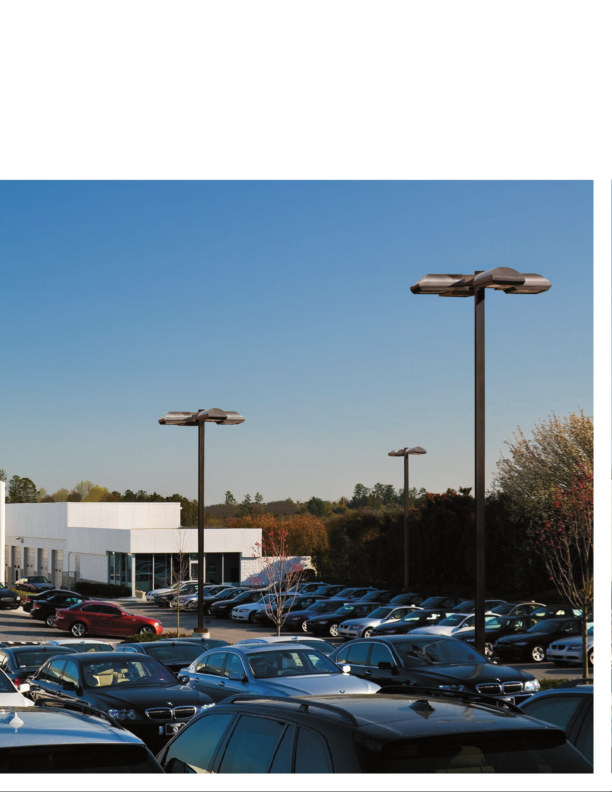
SITE + PARKING | ROADWAY | PATH OF EGRESS
IMPENETRABLE FORM
Coupling precise mechanical design with
premium quality materials, the Talon site light
is constructed to sustain the rigors of outdoor
operation. Thick wall die-cast aluminum
construction and channel set silicone gasketing
form an impenetrable IP65 barrier optimizing
optical efficiency and fixture longevity in the
harshest of environments.
INNOVATIVE FOREFRONT
Forward Leaning— two words that describe
McGraw-Edison’s product development
process and relentless commitment to providing
progressive solutions for emerging market
trends. Regardless of the ordinance governing
your site—spill control, emergency egress,
energy efficiency or curfew compliance, the
Talon offers progressive features to address
rigorous regulatory needs.
Page 4
3
4
PERFORMANCE + VERSATILITY
MAXIMIZE SITE UNIFORMITY
Add sparkle to your site and maximize
pole spacings with sag glass optical
systems offered in both cutoff and
semi-cutoff configurations.
For applications mandating full cutoff,
choose from a complete offering of flat
glass vertical lamp solutions. The vertically
lamped family of optical systems
minimizes light levels directly below
the luminaire while increasing lateral
illumination, maximizing overall site
uniformity. Available in Type III, Area
Round, Area Square, Type IV Automotive
Perimeter and Automotive Front Row [TLL
only] distributions.
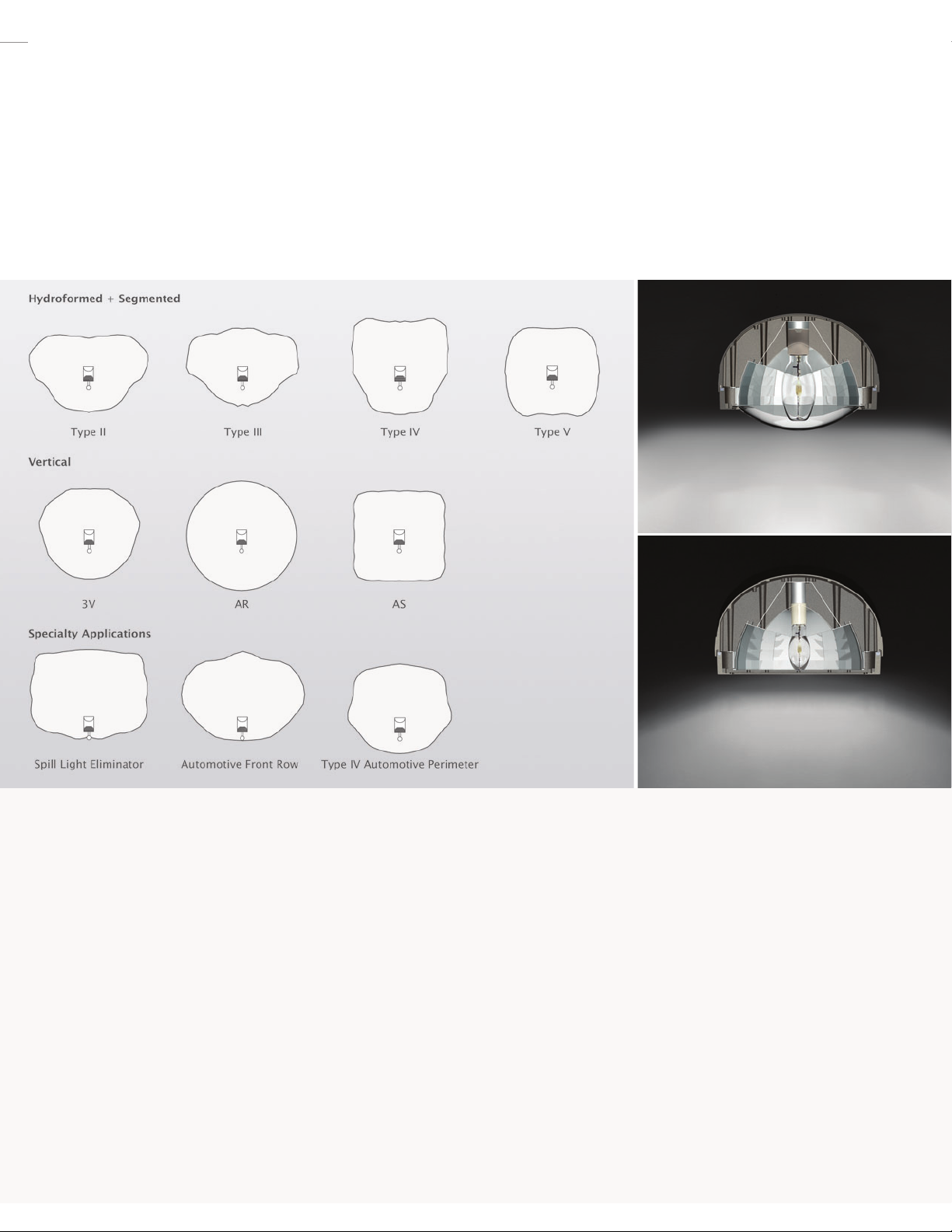
OPTICAL VERSATILITY
Never before has a single luminaire
supported this magnitude of optical
choices, touting four [4] distinct families
of optical assemblies, all with compelling
performance. Hydroformed, segmented,
vertical and specialty application optical
systems allow finely tuned site lighting
solutions with unprecedented levels of
uniformity and control.
Page 5
LEADING SPILL CONTROL
The Spill Light Eliminator [SL] optic is the
industry leader in effective spill light
control, eliminating light beyond one [1]
mounting height behind the pole with no
sacrifice in forward illumination. Used
along site perimeters and property lines,
the Spill Light Eliminator keeps the light
inside and the darkness out.
ROTATIONAL FLEXIBILITY
Maintain uniform site spacing and
fixture orientation with rotatable optical
assemblies. All optics are capable of
rotating in 90° increments allowing for
manipulation of distribution orientation
independent of fixture position.
DARK SKY FRIENDLY
For applications requiring dark sky friendly
solutions, look to full cutoff flat glass
optical assemblies providing focused
illumination with zero uplight and minimal
high angle illumination while retaining
superior uniformity. Available in
hydroformed or segmented Type II, III, IV
V and SL distributions.
OPTICAL SOLUTIONS AS DIVERSE AS THE ENVIRONMENTS THEY ILLUMINATE.
Exterior lighting requirements continue to grow more stringent with added emphasis on light control and system efficiency. Whether the goal of your
site lighting design is safety, general illumination or highlighting prominent features, Talon offers application-specific optical solutions that provide the
highest level of photometric performance and control.
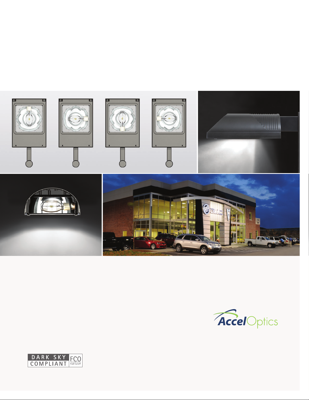
GET NOTICED
Accel Optics, the Talon’s family of
automotive reflector solutions specialize in
focused front row product displays that
engage the customer, general merchandise
lighting that creates an inviting dealership
appearance emanating safety and security,
and perimeter lighting that precisely
frames the automotive dealership lot.
NOTE: In Flat Glass configurations only.
Page 6
5
6
AUTOMOTIVE SOLUTIONS
Page 7
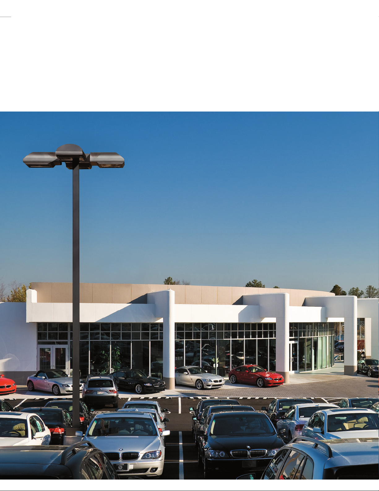
OUTDOOR SITE LIGHTING THAT ENGAGES CUSTOMER AWARENESS.
Exterior site lighting provides the first impression of an automotive dealership and is an outward expression of image. During daytime hours the
exterior site lighting fixture form should be selected to lend focus to dealership architecture and branding. For evening operation, properly
illuminated uniform site lighting will entice customers, drawing them into the dealership.
Page 8
7
8
QUALITY + DURABILITY
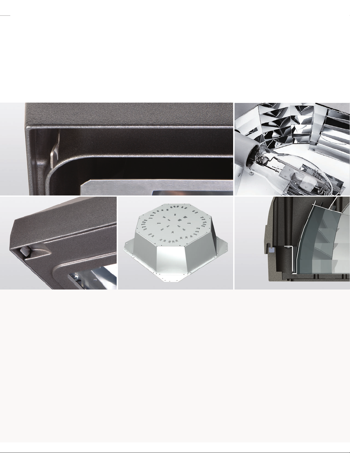
DURABLE CAST CONSTRUCTION
Low-copper alloy die-cast aluminum
construction offers corrosion resistance
while precise tolerance control ensures
tight nesting of the door and housing.
Combining heat extracting reveal channels
with independent optical and electrical
chambers that isolate heat producing
sources, the Talon’s housing design is
both functionally relevant and aesthetically
pleasing.
TOOLLESS ENTRY
Invisibly integrated door retaining latches
allow for a consistent outward aesthetic
while providing maintenance-friendly,
toolless entry into the optical and
electrical chambers. The corrosionresistant stainless spring steel latch
and door receiver pin create an audible
engagement confirming secure door
closure and fixture sealing.
RIGID OPTICAL CONSTRUCTION
A commitment to optical research and
precision build quality result in unequaled
levels of performance and repeatability.
A rigid box enclosure shields segmented
optical facets on all sides from performance
degrading damage while each facet bank is
secured to both the top and bottom of the
enclosure providing repeatable facet
orientation relative to light center.
PREMIUM MATERIALS
Superior optical design and a commitment
to premium 95% reflective sheet aluminum
make Talon’s segmented reflector family
the benchmark of optical excellence.
Reflector facets are flat and unobstructed
by rivets or other means of attachment
which may cause streaks or striations in
the light distribution. First class
construction and attention to detail
ensure dependable performance in
every installation.
INGRESS PROTECTION
“IP” stands for Ingress Protection and is a
rating system recognized internationally
as the standard for electrical products
and other related technologies. The two
numbers proceeding the “IP” individually
callout the fixture’s protection rating
against moisture and airborne
particulates. The channel set silicone
gasketing system incorporated in Talon
is IP65 certified. Dust, insects and
moisture simply have no chance of
penetrating the outer enclosure.
Page 9

CONFIDENCE-INSPIRING QUALITY BEYOND THE SUM OF ITS PARTS.
From the stainless steel hinges to the rugged housing, every detail of the Talon construction is precisely designed with industry leading craftsmanship.
Heavy-wall die-cast aluminum construction, premium TGIC [triglycidyl isocyanurate] polyester powder coat paint and an IP65 rated optical cavity ensure
Talon can endure the harshest environments.
FINISH OPTIONS
McGraw-Edison’s premium polyester powder coatings are enhanced
TGIC based coatings formulated to withstand extended outdoor
exposure. The powders are designed not only to be functional, but
decorative, combining good film appearance with excellent mechanical
and exterior exposure qualities. Formulated with properties similar to
a standard TGIC, the improved weathering characteristics of premium
TGIC result from the integration of a new polyester resin technology.
These coatings consistently display at least twice the gloss retention
of standard TGIC materials in both weatherometer and QUV testing,
making them ideal for outdoor lighting fixtures and poles. Applied to
a nominal 2.5 mil thickness, Talon’s six (6) standard finishes offer
superior protection against fade and wear.
GREY [AP]
WHITE [WH]
BLACK [BK]
DARK PLATINUM [DP]
BRONZE [BZ]
GRAPHITE METALLIC [GM]
100
96
92
88
84
Percentage To Original
0 6 12 18 24
Color Retention Over Time
Months Exposure
TGIC McGraw-Edison Premium
Page 10

9
10
CONTROL + EFFICIENCY
LUMINAIRE CLASSIFICATION
The IESNA’s revised Luminaire Classification System
[TM15-07 revised] creates a new basis of
measurement for site lighting visibility and adjacent
property interaction. This technical memorandum
subdivides the luminaire distribution into smaller
angular zones and subzones to more clearly represent
how much light is emitted at various angles. The values
for each subzone give an indication of the appropriate
use for the luminaire within an application. For dark sky
sensitive areas, the uplight component tells how much
the luminaire will contribute to sky glow.
For applications with strict light trespass regulations,
the back light portion of the distribution helps
determine how much light will reach neighboring
properties. Talon reflector assemblies keep light
on task by contributing as little as 0.0% total upward
illumination and 0.8% total backlight.
Forward Light
Forward Light Low [FL]
Forward Light Mid [FM]
Forward Light High [FH]
Forward Light Very High [FVH]
Back Light
Back Light Low [BL]
Back Light Mid [BM]
Back Light High [BH]
Back Light Very High [BVH]
Uplight
Uplight Low [UL]
Uplight High [UH]
NEIGHBORHOOD AND DARK SKY FRIENDLY
National organizations work to educate the general public on best lighting practices in order to minimize light trespass, reduce sky-glow and improve
nighttime visibility through glare reduction. Experts understand the visual system adapts to surrounding ambient conditions, spurring a move from
universal light level recommendations to a set of custom tailored guidelines for each task based on an application’s lighting zone. When surrounding
conditions are dim, lower levels of light are able to be detected more easily. In these environments, high light level applications can be a source of
discomfort and glare. Careful selection and placement of luminaires eliminates glare and creates a comfortable nighttime environment. Talon’s
assortment of specialty light control optical assemblies combined with a wide array of internal or external house-side shields provide the perfect
solution for every application.
Uplight
180°
UH
100° 100°
UL UL
90° 90°
BVH FVH
80° 80°
BH FH
60° 60°
Back Forward
BM FM
BL FL
30° 30°
0°
[nadir]
Glare
Light Trespass
Uniform Task Illumination
Property
Line
Page 11

STEPPING UP TO THE CHALLENGE.
As visual research advances so too the core understanding of how light interacts with surrounding communities and nocturnal environments.
Utilizing this knowledge, Federal programs, national organizations and industry leaders institute guidelines for illuminating an area safely and securely
while reducing energy, eliminating spill light and minimizing glare. Talon steps up to the challenge, offering innovative solutions to regulatory
compliance issues.
ENERGY EFFICIENCY
With the Federal Energy Independence and Security Act effective January 1, 2009, states are rapidly adopting energy legislation limiting the use of
probe start sources in favor of higher efficiency options. Pulse start technology is being embraced for its efficacy, extended life, high lumen
maintenance, and color consistency. The increased color rendering of a pulse start lamp improves visibility and heightens the overall safety and
security of the site. Higher lumen maintenance levels reduce the number of fixtures needed to achieve a consistent light level over the fixture’s
installed life. Initial savings are compounded by decreased energy consumption and less frequent maintenance requirements. By supporting a full
array of both horizontal and vertical lamp distributions, Talon offers the broadest selection of energy saving pulse start solutions.
CURFEW COMPLIANCE
Certain regulatory documents incorporate energy saving measures beyond standard source efficacy, including curfew regulations calling for close of
business site lighting power reduction. When alternating luminaires are turned off to accomplish the reduction, site lighting uniformity is greatly
reduced, compromising visibility and the feeling of security. The Talon Hi-Low [HL] option enables curfew compliance through an integrated
dimming relay internal to the housing that reduces power while closely maintaining critical-to-safety site lighting uniformity levels.
120
Lumen Output Over Time
100
80
60
40
Lumen Output [In Thousands]
20
0
0 2000 4000 6000 8000 10000
12000 14000 1800016000
Hours of Operation
750W Pulse Start 1000W Probe Start
Alternating Fixture Switching
Hi-Low Dimming
Page 12

Page 13

Page 14

13
14
MOUNTING
Extruded 8" [TLM Talon Medium] or 10
1/2" [TLL Talon Large] aluminum arm
includes internal bolt guides allowing for
easy positioning of fixture during
installation to pole or wall surface.
Standard single carton packaging of
housing, square pole arm and round pole
adapter for contractor friendly arrival of
product on site.
CONSTRUCTION
Heavy-wall, die-cast low-copper alloy
aluminum construction with integral reveal
channels along top surface of housing to
promote heat extraction and prolong
electrical component life. Internal cast-in
wall separates optical and electrical
chambers, allowing components to
operate cooler. One-piece heavy-wall,
die-cast aluminum door frame with
integral cast-in gasket channel seals
optical chamber to an IP65 rating.
Stainless steel latches and hinges.
OPTICAL SYSTEMS
Choice of 14 high efficiency optical
systems utilizing horizontal and vertical
lamp orientations, including five [5]
optional high efficiency segmented optical
systems constructed of premium 95%
reflective anodized aluminum sheet.
Optical segments are rigidly mounted
inside a thick gauge aluminum housing for
superior protection. All segment faces are
clean of rivet heads, tabs or other means
of attachment which may cause streaking
in the light distribution. Standard with
mogul-base socket for HPS and
175-1000W MH. Standard with
medium-base socket for 150W MH and
below. All optical modules feature quick
disconnect wiring plugs and are field
rotatable in 90° increments.
ELECTRICAL
TLM offered standard with ballast and
related electrical componentry hard
mounted to die-cast housing for optimal
heat transfer and improved operating
efficiency. TLM optional and TLL standard,
electrical componentry mounted to a
swing-down galvanized steel power tray
with integral handle. Electrical disconnects
allow tray to be completely removed from
the housing providing ample hand and
tool room for attachment of fixture during
installation.
SPECIFICATION FEATURES
Lamp Standard Door 70-200W 250-400W Lamp 250-1000W
Distribution Orientation Configuration Lens Type Lens Type Orientation Lens Type
2F
Horizontal Recessed Flat/Sag Flat/Sag Horizontal Flat/Sag
2S Horizontal Recessed Flat/Sag Flat/Sag Horizontal Flat/Sag
3F Horizontal Recessed Flat/Sag Flat/Sag Horizontal Flat/Sag
3S Horizontal Recessed Flat/Sag Flat/Sag Horizontal Flat/Sag
4F Horizontal Recessed Flat/Sag Flat/Sag Horizontal Flat/Sag
4S Horizontal Recessed Flat/Sag Flat/Sag Horizontal Flat/Sag
5F Horizontal Recessed Flat/Sag Flat/Sag Horizontal Flat/Sag
5S Horizontal Recessed Flat/Sag Flat/Sag Horizontal Flat/Sag
SL Horizontal Recessed Flat/Sag Flat/Sag Horizontal Flat/Sag
AR Vertical Deep Flat/Sag Sag Vertical Flat/Sag
AS Vertical Deep Flat/Sag Sag Vertical Flat/Sag
3V Vertical Deep Flat/Sag Sag Vertical Flat/Sag
4V Vertical Deep Flat/Sag Sag Vertical Flat/Sag
AF Horizontal Recessed Flat/Sag Flat/Sag Vertical Flat/Sag
TALON MEDIUM [TLM] TALON LARGE [TLL]
Page 15

FINISH
Housing and arm finished in a 5 stage
premium TGIC polyester powder coat
paint, 2.5 mil nominal thickness for
superior protection against fade and
wear. Standard colors include black,
bronze, grey, white, dark platinum,
and graphite metallic. RAL and custom
color matches available. Consult the
McGraw-Edison Architectural Colors
brochure for the complete selection.
MOUNTING CONFIGURATIONS
Talon is available in seven [7] unique luminaire mounting configurations.
NOTE: In Flat Glass configurations only.
DRILLING PATTERNS
Type “M” Wall Mount
Certifications
GM
Graphite Metallic
WH
White
DP
Dark Platinum
BZ
Bronze
BK
Black
AP
Grey
Wall Mount Arm Mount Single
E.P.A.
TLM
Recessed Door 1.22
Deep Door 1.45
TLL 2.51
Arm Mount 2 @ 180°
E.P.A.
TLM
Recessed Door 2.44
Deep Door 2.90
TLL 5.02
Arm Mount 2 @ 90°
E.P.A.
TLM
Recessed Door 2.44
Deep Door 2.90
TLL 5.02
Arm Mount 3 @ 120°
E.P.A.
TLM
Recessed Door 3.23
Deep Door 3.92
TLL 6.85
Arm Mount 3 @ 90°
E.P.A.
TLM
Recessed Door 3.23
Deep Door 3.92
TLL 6.85
Arm Mount 4 @ 90°
E.P.A.
TLM
Recessed Door 3.63
Deep Door 4.43
TLL 7.77
IP65 Rated
CSA Listed
U.L. 1598 Listed
25°C Ambient
ISO 9001
2 5/16"
[59mm]
3/4" [20mm]
dia. hole
2 7/16" [124mm]
4 7/8" [124mm]
[2] 5/8" [16mm]
dia. holes
6 1/2"
[165mm]
8"
[203mm]
12"
[305mm]
4 7/8"
[124mm]
10 1/2"
[267mm]
9/16" [14mm]
Dia. Hole [4]
Page 16

15
16
OPTIONS + ACCESSORIES
ARM MOUNT
Standard 8" [TLM] or 10 1/2" [TLL]
extruded aluminum arm features internal
bolt guides for twin support rods. Round
pole mounting accommodated by utilizing
provided round pole adapter between the
fixture arm and pole shaft.
EXTERNAL MAST ARM ADAPTER [MS]
Cast aluminum mast arm adapter secures
fixture head to nominal 2" [2 3/8" O.D. pipe
size] horizontal steel tenon arm. Adapter
casting slip fits over tenon arm and is
secured via two [2] stainless steel bolts.
WALL MOUNT [WM]
Wall mount plate secured to wall via four [4]
lag bolts [lag bolts supplied by other]. Wall
mount kit includes 1/2" thick steel adapter
plate, a 8" [TLM] or 10 1/2" [TLL] machined
extruded aluminum arm and two [2] fixture
support rods.
TENON ADAPTER
Tenon adapters available to slip fit over poles
equipped with nominal 2" pipe size steel tenon
[2 3/8" O.D., 4" length] or nominal 3" pipe size
steel tenons [3 1/2" O.D., 5" length]. Adapter
secures to tenon via six [6] stainless steel
bolts. For complete configuration availability,
see Tenon Adapters on page 16.
POLYCARBONATE VANDAL SHIELD [VS]
Internally mounted 3/16" thick molded
polycarbonate lens, treated with UV inhibitor
to discourage the gradual discoloration that
results from exposure to sunlight and UV
radiating sources.
QUARTZ RESTRIKE [Q + EM + EM/SC]
Optional quartz restrike [Q] energizes auxiliary
quartz lamp upon power reactivation and
extinguishes once HID lamp re-ignites. Quartz
restrike with time delay [EM] adds cold start
activation. Emergency Separate Circuit [EM/SC]
allows the quartz lamp socket to be wired to
an independent relay controlled power source.
PHOTOCONTROL RECEPTACLE [R]
Fixtures available with gasketed photocontrol
receptacle for mounting a standard NEMA
photocontrol [ordered separately]. Medium
housing also available with a button-style
photocontrol [P].
INTERNAL HOUSE-SIDE SHIELD [HS]
Internal house-side shield reduces light
concentration behind the pole while
maintaining street side efficiency. Internal
house-side shields available on Type II, III, IV
and AF distributions.
EXTERNAL HOUSE-SIDE SHIELD
[MA1213-XX + MA1214-XX]
External house-side shield provides sharp
cutoff behind the pole and shields the lamp
from direct view. Mounted to the door frame
via double-sided VHB adhesive [TLM] or three
[3] stainless steel fasteners [TLL]. Rotatable in
90° increments, the external house-side shield
provides industry leading glare and spill light
control.
[Arm Mount] [WM]
[MS]
Page 17

OPTIONS
[Factory installed and shipped complete with luminaire]
Electrical
F=Single Fuse [120, 277 or 347V]
FF=Double Fuse [208, 240 or 480V]
Q=Quartz Restrike
EM=Quartz Restrike w/Delay [Also Strikes at Cold Start]
EM/SC=Quartz Emergency Separate Circuit
PT=Electrical Power Tray [Standard on TLL]
P=Button Type Photocontrol [TLM Only]
R=NEMA Twistlock Photocontrol Receptacle
HL=Hi/Low Dimming [Vertical Optics Only]
L=Lamp Included
Shields + Doors
HS=Internal House Side Shield
VS=Polycarbonate Vandal Shield [TLM Only]
DD=Deep Door [TLM Only]
Mounting
WM=Wall Mount Bracket with Arm
DM=Direct Mount for Round or Square Pole
DW=Direct Wall Mount
MS=External Mast Arm Adapter [TLM Only]
ACCESSORIES
[Field installed and shipped independent of luminaire]
Electrical
OA/RA1016=NEMA Photocontrol [105-285V]
OA/RA1027=NEMA Photocontrol [480V]
OA/RA1201=NEMA Photocontrol [347V]
OA/RA1013=Shorting Cap
Tenon Adapters
MA1010-XX=Single Tenon Adapter for 3 1/2" O.D. Tenon
MA1011-XX=2 @ 180° Tenon Adapter for 3 1/2" O.D. Tenon
MA1012-XX=3 @ 120° Tenon Adapter for 3 1/2" O.D. Tenon
MA1013-XX=4 @ 90° Tenon Adapter for 3 1/2" O.D. Tenon
MA1014-XX=2 @ 90° Tenon Adapter for 3 1/2" O.D. Tenon
MA1015-XX=2 @ 120° Tenon Adapter for 3 1/2" O.D. Tenon
MA1016-XX=3 @ 90° Tenon Adapter for 3 1/2" O.D. Tenon
MA1017-XX=Single Tenon Adapter for 2 3/8" O.D. Tenon
MA1018-XX=2 @ 180° Tenon Adapter for 2 3/8" O.D. Tenon
MA1019-XX=3 @ 120° Tenon Adapter for 2 3/8" O.D. Tenon
MA1045-XX=4 @ 90° Tenon Adapter for 2 3/8" O.D. Tenon
MA1048-XX=2 @ 90° Tenon Adapter for 2 3/8" O.D. Tenon
MA1049-XX=3 @ 90° Tenon Adapter for 2 3/8" O.D. Tenon
Shields
MA1213-XX=External House-side Shield Kit [TLM Only]
MA1214-XX=External House-side Shield Kit [TLL Only]
DEEP DOOR [DD]
Medium housing vertically lamped optics are
shipped standard with Deep Door. For sites
combining horizontal and vertical optics, specify
the Deep Door [DD] option on horizontal lamp
fixtures to maintain a uniform outward aesthetic.
Reflector shifted downward toward the lens to
maintain optimal photometric performance
[TLM only].
Horizontal optic in recessed door position.
[MA1213 + MA1214]
[HS]
[R]
[Tenon Adapter]
[VS]
[Q + EM + EM/SC]
Horizontal optic in deep door position.
Page 18

17
18
STEEL POLES + BRACKETS
ORDERING INFORMATION
SAMPLE NUMBER: RSS4A20SFM2XG
ISOTACH WIND MAP
This map has been included to
aid in pole selection with regard
to geographic location. Although
a less stringent 25-year mean
recurrence map is sometimes
used by other pole suppliers,
it is our belief that the added
measure of assurance offered
with the use of this map deems
it more desirable.
NOTE: This wind map is intended as a general
guideline only. Consult local engineering
standards to determine the exact wind loading
conditions for your application.
FIXTURE DRILLING [Note handhole position relative to drill locations]
“M2”
Arm Mount 2 @ 180°
E.P.A.
TLM
Recessed Door 2.44
Deep Door 2.90
TLL 5.02
“M1”
Arm Mount Single
E.P.A.
TLM
Recessed Door 1.22
Deep Door 1.45
TLL 2.51
Round Pole [Fixture Drilling]
Square Pole [Fixture Drilling]
“M3”
Arm Mount Triple
2
E.P.A.
TLM
Recessed Door 3.23
Deep Door 3.92
TLL 6.85
“M4”
Arm Mount 4 @ 90°
E.P.A.
TLM
Recessed Door 3.63
Deep Door 4.43
TLL 7.77
“M5”
Arm Mount 2 @ 90°
E.P.A.
TLM
Recessed Door 2.44
Deep Door 2.90
TLL 5.02
“M6”
Arm Mount Triple
3
E.P.A.
TLM
Recessed Door 3.23
Deep Door 3.92
TLL 6.85
“M7”
Arm Mount 2 @ 120°
E.P.A.
TLM
Recessed Door 2.44
Deep Door 2.90
TLL 5.02
NOTES: 1 All shaft sizes nominal. 2 Square poles are 3 @ 90°. Round poles are 3 @ 120°. 3 Round poles are 3 @ 90°. 4 Location is 3' above base—90° from handhole. 5 Outlet is located 4' above base and on same
side of pole as handhole. Receptacle not included, provision only. 6 Aluminum poles only. 7 Maximum wire #8 AWG. 8 Location is 12" below pole top—90° from handhole.
CAUTION: Cooper Lighting poles have been designed to support only the luminaires and equipment originally intended. Miscellaneous items such as pennants, signs, and decorations may cause pole failure
because of overloading. Addition of these items voids the Cooper Lighting warranty. Cooper Lighting will, however, supply information regarding total loading capacity on request. Cooper Lighting
poles are guaranteed only when used in a pole/luminaire or floodlight combination. Any other application of poles, including application without a luminaire or floodlight, voids Cooper Lighting’s
warranty. This warranty specifically excludes failure as the result of a third party act or omission, misuse, unanticipated uses, fatigue failure or similar phenomena resulting from induced vibration,
harmonic oscillation or resonance associated with movement of air currents around the product.
6th & 10th Digit= 11th Digit=
4th Digit= 5th Digit= 7th Digit= Fixture Number & 12th Digit=
1st Digit= 2nd Digit= 3rd Digit= Shaft Dim. Wall Mounting 8th Digit= 9th Digit= Mounting Location Length of 13th Digit=
Shape Shaft Type Material at Base 1Thickness Height Base Type Finish Type of Arms Arm
Accessories
R=Round S=Straight A=Aluminum 0=10" A=.120" 12=12' A=Aluminum L=Dark 2=2" Tenon 1=Single X=None A=1/2" Hub
4
S=Square T=Tapered S=Steel 4=4" D=.180" 15=15' [Round 4-Bolt Platinum [2 3/8" O.D. 2=2 @ 180° B=3/4" Hub
4
5=5" L=.156" 20=20' Pole] F=Dark Bronze 4" Long] 3=Triple
2
C=Convenience
6=6" M=.188" 25=25' S=Steel Square T=Graphite 3=3" Tenon 4=4 @ 90° Outlet
5
7=7" T=.125" 30=30' Base Plate Metallic [3 1/2" O.D. 5=2 @ 90° E=GFI Convenience
8=8" X=.250" 35=35' N=Aluminum V=Grey 5" Long] 6=Triple
3
Outlet
9=9" on Steel 39=39' [Round 3-Bolt W=White M=Talon 7=2 @ 120° F=Vibration Pad
6
[6 3/4" on Pole] X=Custom Drilling X=None G=Ground Lug
7
Aluminum] W=Aluminum Color H=Additional
[Square Pole] [or specify Handhole
8
color] J=Cable Support
Y=Black V=Vibration Damper
L=Drilled for Bumper
Glitter
Page 19

FROM ANCHOR BOLTS TO LUMINAIRE AND EVERYTHING IN BETWEEN.
Cooper Lighting offers a comprehensive line of steel and aluminum poles, brackets and mounting accessories to complete your site lighting
application. Visit www.mcgraw-edison.com to view McGraw-Edison’s entire collection of mounting options.
STEEL POLES [Specification Features]
ROUND STRAIGHT STEEL [RSS]
Fixture Mounting
Drilled or Tenon [Must specify].
Shaft
ASTM A500 grade “B” steel shaft. Shot
blasted and painted with polyester powder
coat.
Handhole
Handhole assembly 3" x 5" on RTS and 5" and
6" on RSS and SSS poles, 2" x 4" on 4" RSS and
SSS poles
Base
ASTM grade steel base plate with ASTM A366
base cover.
Anchorage [4-Bolt]
Anchor bolt per ASTM A576 with [2] nuts,
[2] flat washers, and [1] lock washer. Nuts,
washers and threaded portion of bolt are hot
dip galvanized 3" hook for 3/4" bolt. 4" hook
for 1" bolt.
WARNING: THE USE OF UNAUTHORIZED ACCESSORIES SUCH AS BANNERS, SIGNS OR PENNANTS FOR WHICH THE POLE WAS NOT DESIGNED VOIDS THE COOPER LIGHTING WARRANTY AND MAY RESULT IN POLE
FAILURE CAUSING SERIOUS INJURY OR PROPERTY DAMAGE. COOPER LIGHTING'S POLE WARRANTY IS ALSO VOIDED IF THE LUMINAIRE IS NOT INSTALLED AT TIME OF POLE INSTALLATION. THIS WARRANTY
SPECIFICALLY EXCLUDES FAILURE AS THE RESULT OF A THIRD PARTY ACT OR OMISSION, MISUSE, UNANTICIPATED USES, FATIGUE FAILURE OR SIMILAR PHENOMENA RESULTING FROM INDUCED
VIBRATION, HARMONIC OSCILLATION OR RESONANCE ASSOCIATED WITH MOVEMENT OF AIR CURRENTS AROUND THE PRODUCT.
ROUND TAPERED STEEL [RTS]
SQUARE STRAIGHT STEEL [SSS]
Bolt Anchor
Wall Base Circle Bolt Shaft Bolt Net. Max.
Mtg. Catalog
1, 2
Thickness Square Dia. Proj. Size3Dia. &. Wt. EPA [Sq. Ft.]
4
Load
Height Number [In.] [In.] [In.] [In.] [In.] Length [In.] [Lbs.] At Pole Top [Lbs.]
MH S BC BP B D x AB x H 70 80 90 100
15 RSS4A15S .120 10 1/2 11.0 4 1/2 4 3/4 x 25 x 3 113 11.3 8.1 6.0 4.5 150
20 RSS4A20S .120 10 1/2 11.0 4 1/2 4 3/4 x 25 x 3 144 6.4 4.2 2.7 1.8 200
20 RSS5M20S .188 10 1/2 11.0 4 1/2 5 3/4 x 25 x 3 236 20.4 14.9 11.5 9.2 300
25 RSS5M25S .188 10 1/2 11.0 4 1/2 5 3/4 x 25 x 3 288 13.7 9.6 7.3 5.7 300
30 RSS6M30S .188 12 1/2 12.5 5 6 1 x 36 x 4 419 13.8 10.0 7.5 5.8 300
Bolt Anchor
Wall Base Circle Bolt Shaft Bolt Net. Max.
Mtg. Catalog
1, 2
Thickness Square Dia. Proj. Size
3
Dia. &. Wt. EPA [Sq. Ft.]
4
Load
Height Number [In.] [In.] [In.] [In.] [In.] Length [In.] [Lbs.] At Pole Top [Lbs.]
MH S BC BP B D x AB x H 70 80 90 100
20 RTS6A20S .120 10 1/2 11.0 4 1/2 6.3 x 3.5 3/4 x 25 x 3 173 29.8 22.7 17.8 14.3 400
25 RTS7A25S .120 10 1/2 11.0 4 1/2 7.0 x 3.5 3/4 x 25 x 3 214 28.1 21.4 16.7 13.4 400
30 RTS8A30S .120 12 1/2 12.5 5 7.7 x 3.5 1 x 36 x 4 290 24.0 18.2 14.2 11.3 400
35 RTS8A35S .120 12 1/2 12.5 5 8.4 x 3.5 1 x 36 x 4 342 23.0 17.3 13.5 10.5 400
35 RTS9D35S .180 12 1/2 12.5 5 8.4 x 3.5 1 x 36 x 4 482 38.9 29.6 23.2 18.3 400
39 RTS9A39S .120 12 1/2 12.5 5 8.9 x 3.5 1 x 36 x 4 341 21.5 16.2 12.4 9.5 400
39 RTS9D39S .180 12 1/2 12.5 5 8.9 x 3.5 1 x 36 x 4 536 38.2 29.0 22.5 17.7 400
Bolt Anchor
Wall Base Circle Bolt Shaft Bolt Net. Max.
Mtg. Catalog
1, 2
Thickness Square Dia. Proj. Size
3
Dia. &. Wt. EPA [Sq. Ft.]
4
Load
Height Number [In.] [In.] [In.] [In.] [In.] Length [In.] [Lbs.] At Pole Top [Lbs.]
MH S BC BP B D x AB x H 70 80 90 100
15 SSS4A15S .120 10 1/2 11.0 4 1/2 4 3/4 x 25 x 3 133 19.6 14.4 10.8 8.2 150
20 SSS4A20S .120 10 1/2 11.0 4 1/2 4 3/4 x 25 x 3 152 12.9 9.1 6.5 4.6 200
20 SSS5A20S .120 10 1/2 11.0 4 1/2 5 3/4 x 25 x 3 202 21.9 15.7 11.6 8.5 200
25 SSS4A25S .120 10 1/2 11.0 4 1/2 4 3/4 x 25 x 3 208 8.7 5.6 3.6 2.1 200
25 SSS5A25S .120 10 1/2 11.0 4 1/2 5 3/4 x 25 x 3 248 15.5 10.5 7.2 4.8 200
25 SSS5M25S .188 10 1/2 11.0 4 1/2 5 3/4 x 25 x 3 308 28.1 20.0 14.5 10.6 300
25 SSS6A25S .120 12 1/2 12.5 5 6 1 x 36 x 4 295 24.1 16.8 12.0 8.5 200
30 SSS5A30S .120 10 1/2 11.0 4 1/2 5 3/4 x 25 x 3 293 8.2 4.6 2.1 -- 300
30 SSS5M30S .188 10 1/2 11.0 4 1/2 5 3/4 x 25 x 3 369 15.2 9.5 5.8 3.1 300
30 SSS6A30S .120 12 1/2 12.5 5 6 1 x 36 x 4 347 14.0 8.7 5.0 2.5 300
30 SSS6M30S .188 12 1/2 12.5 5 6 1 x 36 x 4 505 26.4 18.1 12.5 8.4 300
NOTES: 1 Catalog number does not include anchor bolts [BEFORE INSTALLING ANCHOR BOLTS MAKE SURE PROPER ANCHOR BOLT TEMPLATE IS OBTAINED FROM COOPER
LIGHTING]. 2 Tenon size or machining for rectangular arms must be specified. handhole is located 180° from single arm. 3 Shaft size, base plate, anchor bolts and
projections may vary slightly—all dimensions nominal. 4 EPA’s based on shaft properties with wind normal to flat. EPA’s calculated using base wind velocity as indicated
plus 30% gust factor.
INTERNAL SQUARE SLIPFITTER BRACKET [ISBD]
Internal square slipfitter brackets designed to accept two [2] or three [3] arm mount fixtures and slip fit internally to a 4", 5" or 6" square straight steel
pole. Assembly secured to square straight steel M4 drill pattern without any modifications.
Catalog Pole Mounting Net Wt.
Number Dimen. Config. E.P.A [Lbs.]
2 Arm Mountings
ISBD-4-2L-M-BZ 4" 2 In-Line 1.98 50
ISBD-5-2L-M-BZ 5" 2 In-Line 1.98 52
ISBD-6-2L-M-BZ 6" 2 In-Line 1.98 70
3 Arm Mountings
ISBD-4-3L-M-BZ 4" 3 In-Line 3.72 87
ISBD-5-3L-M-BZ 5" 3 In Line 3.72 89
ISBD-6-3L-M-BZ 6" 3 In-Line 3.72 95
Fixed Tenon
or Drilled
Mtg.
Ht.
[MH]
[S]
[BC]
Shaft Size
[B]
Handhole
12 5/16 "
Base
Square
[D]
[BP]
[AB]
[H]
7" Sq.
[177mm]
18" [457mm]
18" [457mm]
7" Sq.
[177mm]
30" [762mm]
30" [762mm]
3 1/2" Sq. [89mm]
4 1/2" Sq. [115mm]
5 1/2" Sq. [140mm]
5" [127mm]
6" [153mm]
3 1/2" Sq. [89mm]
4 1/2" Sq. [115mm]
5 1/2" Sq. [140mm]
5" [127mm]
6" [153mm]
Page 20

19
20
ALUMINUM POLES + PHOTOMETRICS
ALUMINUM POLES [Specification Features]
ROUND STRAIGHT ALUMINUM [RSA]
Fixture Mounting
Drilled or Tenon [Must specify].
Shaft
6005-T6 aluminum alloy with polished finish.
Handhole
Flush reinforced 2 3/8" x 4 1/2" for 4" shafts.
Handhole assembly with internal reinforcing
frame. 3" X 5" for 6" shafts, 4" x 6" for 7", 8"
and 10" shafts. Ground lug located opposite
handhole opening drilled & tapped for 3/8"
16NC-2 grounding screw.
Base
356-T6 cast aluminum alloy shoe base with
aluminum alloy knock-in bolt covers or base
cover dependent on base type.
Anchorage
Anchor bolt per ASTM A576 with [1] nut, [1] flat
washer, and [2] shims. Nuts, washers and
threaded portion of bolt are hot dip galvanized.
WARNING: THE USE OF UNAUTHORIZED ACCESSORIES SUCH AS BANNERS, SIGNS OR PENNANTS FOR WHICH THE POLE WAS NOT DESIGNED VOIDS THE COOPER LIGHTING WARRANTY AND MAY RESULT IN POLE
FAILURE CAUSING SERIOUS INJURY OR PROPERTY DAMAGE. COOPER LIGHTING'S POLE WARRANTY IS ALSO VOIDED IF THE LUMINAIRE IS NOT INSTALLED AT TIME OF POLE INSTALLATION. THIS WARRANTY
SPECIFICALLY EXCLUDES FAILURE AS THE RESULT OF A THIRD PARTY ACT OR OMISSION, MISUSE, UNANTICIPATED USES, FATIGUE FAILURE OR SIMILAR PHENOMENA RESULTING FROM INDUCED
VIBRATION, HARMONIC OSCILLATION OR RESONANCE ASSOCIATED WITH MOVEMENT OF AIR CURRENTS AROUND THE PRODUCT.
Bolt Anchor
Mtg. Wall Shaft Bolt Circle Bolt Net. Max.
Height Catalog Thickness Dia. Proj. Dia. Dia. & Wt. EPA [Sq. Ft.]
3, 4
Load
[Ft.] Number
1
[In.] [In.] [In.] [In.] Length [In.] [Lbs.] At Pole Top [Lbs.]
MH B BP BC D x AB x H 70 80 90 100
15 RSA4M15N .188 4 1 7/8 6 3/4 3/4 x 17 x 3 33 6.4 4.2 2.8 1.8 100
15 RSA5T15N .125 5 1 7/8 7 3/4 3/4 x 17 x 3 40 11.5 8.2 6.2 4.9 100
18 RSA4M18N
2
.188 4 1 7/8 6 3/4 3/4 x 17 x 3 54 7.2 4.8 3.1 2.1 100
18 RSA5M18N .188 5 1 7/8 7 3/4 3/4 x 17 x 3 66 13.0 9.2 7.0 5.5 150
20 RSA5M20N .188 5 1 7/8 7 3/4 3/4 x 17 x 3 73 10.3 7.1 5.3 4.1 150
ROUND TAPERED ALUMINUM [RTA]
Base Bolt Anchor
Mtg. Wall Dia. or Shaft Bolt Circle Bolt Net. Max.
Height Catalog Thickness Square Dia. Proj. Dia. Dia. & Wt. EPA [Sq. Ft.]
3, 4
Load
[Ft.] Number1[In.] [In.] [In.] [In.] [In.] Length [In.] [Lbs.] At Pole Top [Lbs.]
MH B BP BC D x AB x H 70 80 90 100
12 RTA4T12N .125 9 1/4 4 x 3 1 7/8 6 3/4 3/4 x 17 x 3 25 10.1 7.3 5.3 4.0 100
15 RTA4T15N .125 9 1/4 4 x 3 1 7/8 6 3/4 3/4 x 17 x 3 30 7.0 4.8 3.3 2.3 100
15 RTA5T15N .125 10 1/2 5 x 3 1 7/8 7 3/4 3/4 x 17 x 3 33 12.7 9.1 6.7 5.1 100
18 RTA5T18N .125 10 1/2 5 x 3 1 7/8 7 3/4 3/4 x 17 x 3 39 8.8 6.0 4.3 3.1 100
18 RTA6L18A .156 10 1/4 6 x 4 2 1/8 9 3/8 3/4 x 17 x 3 57 18.2 13.3 10.2 8.0 100
20 RTA5T20N .125 9 1/4 5 x 3 1 7/8 8 1/2 3/4 x 17 x 3 43 7.0 4.6 3.1 2.1 100
20 RTA6L20A .156 10 1/4 6 x 4 2 1/8 9 3/8 3/4 x 17 x 3 64 14.7 10.6 7.9 6.2 150
25 RTA6L25A
2
.156 10 1/4 6 x 4 2 1/8 9 3/8 3/4 x 17 x 3 81 8.8 5.9 4.1 3.0 150
25 RTA8L25A
2
.156 11 5/8 8 x 4 1/2 2 3/4 11 1/2 1 x 36 x 4 106 20.3 15.0 11.5 9.0 200
30 RTA7L30A
2
.156 10 5/8 7 x 4 2 3/4 10 1/2 1 x 36 x 4 108 9.0 5.9 4.1 3.0 150
30 RTA8L30A
2
.156 11 5/8 8 x 4 1/2 2 3/4 11 1/2 1 x 36 x 4 117 13.5 9.6 7.2 5.5 200
30 RTA0L30A
2
.156 14 1/2 10 x 6 2 7/8 14 1/2 1 x 36 x 4 152 25.8 19.3 14.8 11.5 250
35 RTA8L35A
2
.156 11 5/8 8 x 4 1/2 2 3/4 11 1/2 1 x 36 x 4 140 9.0 6.0 4.3 3.1 150
35 RTA0L35A2.156 14 1/2 10 x 6 2 7/8 14 1/2 1 x 36 x 4 180 19.0 14.0 10.5 8.0 200
SQUARE STRAIGHT ALUMINUM [SSA]
Bolt Anchor
Mtg. Wall Shaft Bolt Circle Bolt Net. Max.
Height Catalog Thickness Dia. Proj. Dia. Dia. & Wt. EPA [Sq. Ft.]
3, 4
Load
[Ft.] Number
1
[In.] [In.] [In.] [In.] Length [In.] [Lbs.] At Pole Top [Lbs.]
MH B BP BC D x AB x H 70 80 90 100
12 SSA4T12W .125 4 1 3/4 9 3/4 x 17 x 3 32 16.0 11.5 8.5 6.3 260
15 SSA4T15W .125 4 1 3/4 9 3/4 x 17 x 3 39 9.1 6.2 4.2 2.8 200
15 SSA4M15W .188 4 1 3/4 9 3/4 x 17 x 3 55 14.8 10.6 7.7 5.6 200
15 SSA5T15W .125 5 2 11 3/4 x 17 x 3 52 16.0 11.3 8.1 5.8 260
18 SSA4T18W .125 4 1 3/4 9 3/4 x 17 x 3 46 6.4 4.0 2.3 1.1 100
18 SSA4M18W .188 4 1 3/4 9 3/4 x 17 x 3 66 11.0 7.4 5.0 3.3 150
18 SSA5T18W .125 5 2 11 3/4 x 17 x 3 61 11.8 7.8 5.1 3.2 150
18 SSA5M18W .188 5 2 11 3/4 x 17 x 3 85 19.2 13.5 9.6 6.8 260
20 SSA4M20W .188 4 1 3/4 9 3/4 x 17 x 3 72 8.8 5.6 3.5 1.9 150
20 SSA5T20W .125 5 2 11 3/4 x 17 x 3 66 9.5 5.9 3.5 1.7 100
20 SSA5M20W .188 5 2 11 3/4 x 17 x 3 94 16.4 11.2 7.6 5.0 150
25 SSA5M25W .188 5 2 11 3/4 x 17 x 3 115 10.2 6.0 3.2 1.1 100
25 SSA6M25W .188 6 2 12 1/2 1 x 36 x 4 140 16.6 10.6 6.5 3.5 260
30 SSA6X30W .250 6 2 12 1/2 1 x 36 x 4 215 14.8 9.0 5.0 2.1 260
30 SSA9X30W .250 6 3/4 2 3/4 14 1/4 1 x 36 x 4 237 21.1 13.5 8.2 4.5 260
NOTES: 1 Catalog number does not include anchor bolts. 2 Factory installed vibration dampeners. 3 Where higher EPA/wind speed capability or mounting height is required,
other shaft dimensions and/or wall thickness are available. Consult Cooper Lighting representative for pricing and lead times. The above E.P.A. capacities are based on
loading from [1994] and pole drag coefficients from [2001] American Association of State Highway and Transportation Officials Specification. 4 EPAs based on shaft
properties with wind normal to flat. EPAs calculated using base wind velocity as indicated plus 30% gust factor.
Fixed Tenon
or Drilled
Mtg.
Ht.
[MH]
Square
Round
Shaft Size [B]
Round Straight
Shaft Size [B]
[D]
[H]
Handhole
12 5/16 "
Handhole
[BC]
Base
Square
[BC]
Base
Square
18"
[S]
[S]
[BP]
[AB]
Page 21

PHOTOMETRICS [Complete IES files available at www.cooperlighting.com]
FOOTCANDLE TABLE
Select mounting height and read across for
footcandle values of each isofootcandle
line. Distance in units of mounting height.
Mounting Footcandle Values for
Height Isofootcandle Lines
AB C D E
175W [3V/AS]
15' 1.70 0.85 0.34 0.17 --
20' 1.00 0.50 0.20 0.10 --
25' 0.64 0.32 0.13 0.06 --
250W [SL]/400W [3S]
20' 2.00 1.00 0.50 0.20 0.10
25' 1.28 0.64 0.32 0.13 0.06
30' 0.88 0.44 0.22 0.09 0.04
TLM-175-MH-3V-FG
175-Watt MH
14,000-Lumen Clear Lamp
Type III Vertical
Flat Glass
TLM-175-MH-AS-FG
175-Watt MH
14,000-Lumen Clear Lamp
Area Square
Flat Glass
TLM-250-MH-SL-FG
250-Watt MH
20,500-Lumen Clear Lamp
Spill Light Eliminator
Flat Glass
TLM-400-MH-3S-FG
400-Watt MH
36,000-Lumen Clear Lamp
Type III Segmented
Flat Glass
FOOTCANDLE TABLE
Select mounting height and read across for
footcandle values of each isofootcandle
line. Distance in units of mounting height.
Mounting Footcandle Values for
Height Isofootcandle Lines
AB C D E
400W [3V/4V/5S/AR]
20' 3.00 1.50 0.75 0.30 0.15
25' 2.00 1.00 0.50 0.20 0.10
30' 1.38 0.69 0.34 0.13 0.06
TLM-400-MH-3V-SG
400-Watt MH
36,000-Lumen Clear Lamp
Type III Vertical
Sag Glass
ABCDE
TLM-400-MH-4V-SG
400-Watt MH
36,000-Lumen Clear Lamp
Type IV Automotive Perimeter
Sag Glass
TLM-400-MH-5S-FG
400-Watt MH
36,000-Lumen Clear Lamp
Type V Segmented
Flat Glass
TLM-400-MH-AR-SG
400-Watt MH
36,000-Lumen Clear Lamp
Area Round
Sag Glass
FOOTCANDLE TABLE
Select mounting height and read across for
footcandle values of each isofootcandle
line. Distance in units of mounting height.
Mounting Footcandle Values for
Height Isofootcandle Lines
AB C D E
400W [3F]/1000W [AS/SL]
25' 2.88 1.44 0.72 0.29 0.14
30' 2.00 1.00 0.50 0.20 0.10
35' 1.46 0.73 0.37 0.15 0.07
400W [AR]
25' 1.44 0.72 0.29 0.14 --
30' 1.00 0.50 0.20 0.10 --
35' 0.73 0.37 0.15 0.07 --
TLL-400-MH-3F-FG
400-Watt MH
36,000-Lumen Clear Lamp
Type III Formed
Flat Glass
TLL-400-MH-AR-SG
400-Watt MH
36,000-Lumen Clear Lamp
Area Round
Sag Glass
TLL-1000-MH-AS-FG
1000-Watt MH
110,000-Lumen Clear Lamp
Area Square
Flat Glass
TLL-1000-MH-SL-FG
1000-Watt MH
110,000-Lumen Clear Lamp
Spill Light Eliminator
Flat Glass
FOOTCANDLE TABLE
Select mounting height and read across for
footcandle values of each isofootcandle
line. Distance in units of mounting height.
Mounting Footcandle Values for
Height Isofootcandle Lines
AB C D E
1000W [3V/4V-HS/3V-EHS]
25' 7.20 2.88 1.44 0.72 0.29
30' 5.00 2.00 1.00 0.50 0.20
35' 3.65 1.46 0.73 0.37 0.15
1000W [AF]
25' 30.00 10.00 3.00 1.00 0.20
27' 25.50 8.50 2.55 0.85 0.17
30' 20.70 6.90 2.07 0.69 0.14
TLL-1000-MH-3V-FG
1000-Watt MH
110,000-Lumen Clear Lamp
Type III Vertical
Flat Glass
TLL-1000-MH-4V-FG-HS
1000-Watt MH
110,000-Lumen Clear Lamp
Type IV Automotive Perimeter
Flat Glass— House-Side Shield
TLL-1000-MH-3V-FG-EHS
1000-Watt MH
110,000-Lumen Clear Lamp
Type III Vertical
Flat Glass— External
House-Side Shield
ABCDE
TLL-1000-MH-AF-FG
1000-Watt MH
110,000-Lumen Clear Lamp
Automotive Front Row
Flat Glass
AB CD
AB C DE
AB CD
ABCDE
AB CDE
ABCDE
ABCDE
AB C DE
ABCDE
AB C D
ABCDE
ABCDE
AB CDE
ABCDE
Page 22

21
22
TLM TALON MEDIUM
ORDERING INFORMATION
SAMPLE NUMBER: TLM-400-MH-MT-3F-FG-BK-HS
VOLTAGE
5
120=120V
208=208V
240=240V
277=277V
347=347V
480=480V
DT=Dual-Tap
6
MT=Multi-Tap
6
TT=Triple-Tap
6
5T=5-Tap
6,7
DISTRIBUTION
Horizontal Lamp
2F=Type II Formed
2S=Type II Segmented
3F=Type III Formed
3S=Type III Segmented
4F=Type IV Formed
4S=Type IV Segmented
5F=Type V Formed
5S=Type V Segmented
SL=Spill Light Eliminator
AF=Automotive Front Row
Vertical Lamp
3V=Type III Vertical
8
4V=Type IV Automotive Perimeter
8
AR=Area Round
8
AS=Area Square
8
LENS TYPE
FG=Flat Glass
SG=Sag Glass
COLOR
9
[add as suffix/
must specify]
BK=Black
AP=Grey
BZ=Bronze
WH=White
DP=Dark Platinum
GM=Graphite Metallic
PRODUCT
FAMILY
1
TLM=Talon
Site
Medium
LAMP TYPE
MH=Metal Halide
MP=Pulse Start
Metal Halide
HPS=High Pressure
Sodium
LAMP
WATTAGE
2
70=70W
100=100W
150=150W
175=175W
250=250W
320=320W
3, 4
350=350W
3, 4
400=400W
4
OPTIONS [add as suffix]
F=Single Fuse [120, 277 or 347V]
10
FF=Double Fuse [208, 240 or 480V]
10
Q=Quartz Restrike
11
EM=Quartz Restrike w/Delay [Also Strikes at Cold Start]
11
EM/SC=Quartz Emergency Separate Circuit
11
PT=Electrical Power Tray
P=Button Type Photocontrol [120, 208, 240 or 277V]
10
R=NEMA Twistlock Photocontrol Receptacle
HS=Internal House-side Shield
12
VS=Polycarbonate Vandal Shield
DD=Deep Door
WM=Wall Mount with 8" Arm
DM=Direct Mount for Round or Square Pole
DW=Direct Wall Mount
MS=External Mast Arm Adapter
HL=Hi/Low Dimming
13
L=Lamp Included
OPTIONS + ACCESSORIES [Must be listed in the order shown and separated by a dash]
ACCESSORIES [order separately/replace XX with color designation]
OPTIONS +
ACCESSORIES
[See Below]
NOTES: 1 8" arm and round pole adapter included with fixture. 2 Standard with mogul-base socket for HPS and 175-400W MH. Standard with medium-base socket for 150W MH and below. 3 320/350W Pulse
Start Metal Halide lamps only. 4 Requires reduced envelope lamp. 5 Products also available in non-US voltages and 50Hz for international markets. Consult factory for availability and ordering information.
6 Dual-Tap is 120/277V wired 277V. Multi-Tap is 120/208/240/277V wired 277V. Triple-Tap ballast is 120/277/347V wired 347V. 5-Tap is 120/208/240/277/480V wired 480V. 7 Available for
250-400W only. 8 Vertical lamp optics ship standard with deep door. 250-400W vertically lamped optics not available with flat glass. 9 Custom and RAL color matching available upon request. Consult
Cooper Lighting Representative for further information. 10 Must specify voltage. 11 Quartz options not available with SL and AF optics. 12 House-side shield not available on 5S, 5F, AS, AR, and SL optics.
13 Requires vertical lamp orientation. Provides 24V low voltage leads used in dimming controls. 14 Specifications and dimensions subject to change without notice.
Lamp Type Wattage
Metal Halide
175, 250, 400W
High Pressure Sodium 70, 100, 150, 250, 400W
Pulse Start Metal Halide 70, 100, 150, 250, 320, 350, 400W
DIMENSIONS
WATTAGE TABLE
IP65 Rated
25° C Ambient Temperature
U.L. 1598 Listed
CSA Listed
ISO 9001
FCO [Full Cutoff] Flat Glass Only
CERTIFICATIONS
STANDARD COLORS
GM
Graphite Metallic
WH
White
DP
Dark Platinum
BZ
Bronze
BK
Black
AP
Grey
DRILLING PATTERNS
TYPE “M” WALL MOUNT
Effective Projected Area
Recessed Door w/o Arm: 0.79
Deep Door w/o Arm: 1.02
8" Arm: 0.43
EPA
Approximate Net Weight
Recessed Door 47 lbs. [21.79 kgs.]
Deep Door 52 lbs. [23.63 kgs.]
SHIPPING DATA
OA/RA1016=NEMA Photocontrol [105-285V]
OA/RA1027=NEMA Photocontrol [480V]
OA/RA1201=NEMA Photocontrol [347V]
OA/RA1013=Shorting Cap
MA1010-XX=Single Tenon Adapter for 3 1/2" O.D. Tenon
MA1011-XX=2 @ 180° Tenon Adapter for 3 1/2" O.D. Tenon
MA1012-XX=3 @ 120° Tenon Adapter for 3 1/2" O.D. Tenon
MA1013-XX=4 @ 90° Tenon Adapter for 3 1/2" O.D. Tenon
MA1014-XX=2 @ 90° Tenon Adapter for 3 1/2" O.D. Tenon
MA1015-XX=2 @ 120° Tenon Adapter for 3 1/2" O.D. Tenon
MA1016-XX=3 @ 90° Tenon Adapter for 3 1/2" O.D. Tenon
MA1017-XX=Single Tenon Adapter for 2 3/8" O.D. Tenon
MA1018-XX=2 @ 180° Tenon Adapter for 2 3/8" O.D. Tenon
MA1019-XX=3 @ 120° Tenon Adapter for 2 3/8" O.D. Tenon
MA1045-XX=4 @ 90° Tenon Adapter for 2 3/8" O.D. Tenon
MA1048-XX=2 @ 90° Tenon Adapter for 2 3/8" O.D. Tenon
MA1049-XX=3 @ 90° Tenon Adapter for 2 3/8" O.D. Tenon
MA1213-XX=External House-side Shield Kit [EPA=0.38]
[203mm]
16 1/4" [412mm]
8"
[302mm]
1 3/4"
[45mm]
11 7/8"
23 1/4" [590mm]
8"
[203mm]
2 5/16"
[59mm]
3/4" [20mm]
dia. hole
2 7/16" [124mm]
4 7/8" [124mm]
[2] 5/8" [16mm]
dia. holes
12"
[305mm]
4 7/8"
[124mm]
10 1/2"
[267mm]
6 1/2"
[165mm]
8"
[203mm]
9/16" [14mm]
Dia. Hole [4]
Page 23

TLL TALON LARGE
ORDERING INFORMATION
SAMPLE NUMBER: TLL-1000-MH-5T-SL-FG-BK
VOLTAGE
4
120=120V
208=208V
240=240V
277=277V
347=347V
480=480V
DT=Dual-Tap
5
MT=Multi-Tap
5
TT=Triple-Tap
5
5T=5-Tap
5
DISTRIBUTION
Horizontal Lamp
2F=Type II Formed
2S=Type II Segmented
3, 6
3F=Type III Formed
3S=Type III Segmented
3, 6
4F=Type IV Formed
4S=Type IV Segmented
3, 6
5F=Type V Formed
5S=Type V Segmented
3, 6
SL=Spill Light Eliminator
Vertical Lamp
3V=Type III Vertical
4V=Type IV Automotive Perimeter
AR=Area Round
AS=Area Square
AF=Automotive Front Row
LENS TYPE
FG=Flat Glass
SG=Sag Glass
COLOR
7
[add as suffix/
must specify]
BK=Black
AP=Grey
BZ=Bronze
WH=White
DP=Dark Platinum
GM=Graphite Metallic
PRODUCT
FAMILY
1
TLL=Talon
Site
Large
LAMP TYPE
MH=Metal Halide
MP=Pulse Start
Metal Halide
HPS=High
Pressure
Sodium
LAMP
WATTAGE
250=250W
320=320W
2
350=350W
2
400=400W
750=750W
875=875W
2
1000=1000W
3
Lamp Type Wattage
Metal Halide
250, 400, 1000W
High Pressure Sodium 250, 400, 750, 1000W
Pulse Start Metal Halide 250, 320, 350, 400, 750, 875, 1000W
OPTIONS [add as suffix]
F=Single Fuse [120, 277 or 347V]
8
FF=Double Fuse [208, 240 or 480V]
8
Q=Quartz Restrike
9
EM=Quartz Restrike w/Delay [Also Strikes at Cold Start]
9
EM/SC=Quartz Emergency Separate Circuit
9
R=NEMA Twistlock Photocontrol Receptacle
HS=Internal House-side Shield
10
WM=Wall Mount with 10 1/2" Arm
DM=Direct Mount for Round or Square Pole
DW=Direct Wall Mount
HL=Hi/Low Dimming
11
L=Lamp Included
OA/RA1016=NEMA Photocontrol [105-285V]
OA/RA1027=NEMA Photocontrol [480V]
OA/RA1201=NEMA Photocontrol [347V]
OA/RA1013=Shorting Cap
MA1010-XX=Single Tenon Adapter for 3 1/2" O.D. Tenon
MA1011-XX=2 @ 180° Tenon Adapter for 3 1/2" O.D. Tenon
MA1012-XX=3 @ 120° Tenon Adapter for 3 1/2" O.D. Tenon
MA1013-XX=4 @ 90° Tenon Adapter for 3 1/2" O.D. Tenon
MA1014-XX=2 @ 90° Tenon Adapter for 3 1/2" O.D. Tenon
MA1015-XX=2 @ 120° Tenon Adapter for 3 1/2" O.D. Tenon
MA1016-XX=3 @ 90° Tenon Adapter for 3 1/2" O.D. Tenon
MA1017-XX=Single Tenon Adapter for 2 3/8" O.D. Tenon
MA1018-XX=2 @ 180° Tenon Adapter for 2 3/8" O.D. Tenon
MA1019-XX=3 @ 120° Tenon Adapter for 2 3/8" O.D. Tenon
MA1045-XX=4 @ 90° Tenon Adapter for 2 3/8" O.D. Tenon
MA1048-XX=2 @ 90° Tenon Adapter for 2 3/8" O.D. Tenon
MA1049-XX=3 @ 90° Tenon Adapter for 2 3/8" O.D. Tenon
MA1214-XX=External House-side Shield Kit [EPA=0.94]
OPTIONS + ACCESSORIES [Must be listed in the order shown and separated by a dash]
DIMENSIONS
WATTAGE TABLE
IP65 Rated
25° C Ambient Temperature
U.L. 1598 Listed
CSA Listed
ISO 9001
FCO [Full Cutoff] Flat Glass Only
CERTIFICATIONS
DRILLING PATTERNS
TYPE “M” WALL MOUNT
ACCESSORIES [order separately/replace XX with color designation]
OPTIONS +
ACCESSORIES
[See Below]
NOTES: 1 10 1/2" arm and round pole adapter included with fixture. 2 320/350/875W Pulse Start Metal Halide lamps only. 3 Requires reduced envelope lamp. 4 Products also available in non-US voltages and
50Hz for international markets. Consult factory for availability and ordering information. 5 Dual-Tap is 120/277V wired 277V. Multi-Tap is 120/208/240/277V wired 277V. Triple-Tap ballast is
120/277/347V wired 347V. 5-Tap is 120/208/240/277/480V wired 480V. 6 Maximum wattage on segmented optical distributions is 400W. 7 Custom and RAL color matching available upon request.
Consult Cooper Lighting Representative for further information. 8 Must specify voltage. 9 Quartz options not available with SL and AF optics. 10 House-side shield not available on 5S, 5F, AS, AR, and SL
optics. 11 Requires vertical lamp orientation. Provides 24V low voltage leads used in dimming controls. 12 Specifications and dimensions subject to change without notice.
STANDARD COLORS
GM
Graphite Metallic
WH
White
DP
Dark Platinum
BZ
Bronze
BK
Black
AP
Grey
Effective Projected Area
Without Arm: 1.82
10 1/2" Arm: 0.6
EPA
Approximate Net Weight
400W 91 lbs. [41.36 kgs.]
1000W 98 lbs. [44.54 kgs.]
SHIPPING DATA
21 5/8" [549mm]
14 1/8"
[359mm]
3 1/8"
[79mm]
31" [787mm]
2 5/16"
[59mm]
3/4" [20mm]
dia. hole
2 7/16" [124mm]
10 1/2"
[267mm]
4 7/8" [124mm]
[2] 5/8" [16mm]
dia. holes
12"
[305mm]
4 7/8"
[124mm]
10 1/2"
[267mm]
6 1/2"
[165mm]
8"
[203mm]
9/16" [14mm]
Dia. Hole [4]
Page 24

Cooper Lighting
Customer First Center
1121 Highway 74 South
Peachtree City, GA 30269
P: 770-486-4800
F: 770-486-4801
www.cooperlighting.com
International Sales, USA
Cooper Lighting
1121 Highway 74 South
Peachtree City, GA 30269
P: 770-486-4800
F: 770-486-4801
Canada
Cooper Lighting
5925 McLaughlin Road
Mississauga, Ontario L5R 1B8
P: 905-507-4000
F: 905-568-7049
The Cooper Lighting Family
Halo
Metalux
Lumark
Sure-Lites
Neo-Ray
Corelite
Portfolio
Iris
Shaper
io
Lumière
Invue
McGraw-Edison
Streetworks
Fail-Safe
MWS
DLS
RSA
Ametrix
Printed in USAADH080321
Domestic Facilities
Cranbury, New Jersey
Elk Grove Village, Illinois
Irving, Texas
Ontario, California
Peachtree City, Georgia
Canadian Facility
Calgary, Alberta T2E 7V9
Cooper Industries, Ltd.
600 Travis, Ste. 5800
Houston, TX 77002-1001
P: 713-209-8400
www.cooperindustries.com
Cooper Lighting, McGraw-Edison, Talon and Accel Optics are valuable trademarks of Cooper Industries in the United States and other countries.
You are not permitted to use the Cooper Trademarks without the prior written consent of Cooper Industries.
 Loading...