

Page 1
Vault
These installation instructions are valid with the above Ametrix styles.
C-Scroll
Roundel
Installation Instructions
Sheet 1 of 2
Large, OUTDOOR
YR (16.5")
(Yoke mount, Remote ballast)
Visor and Non-Visor
Warning
that all sources of power are turned off. All
work must meet local/national codes and be
performed by a certified electrician.
mount fixtures vertically.
: Before starting any work ensure
Do not
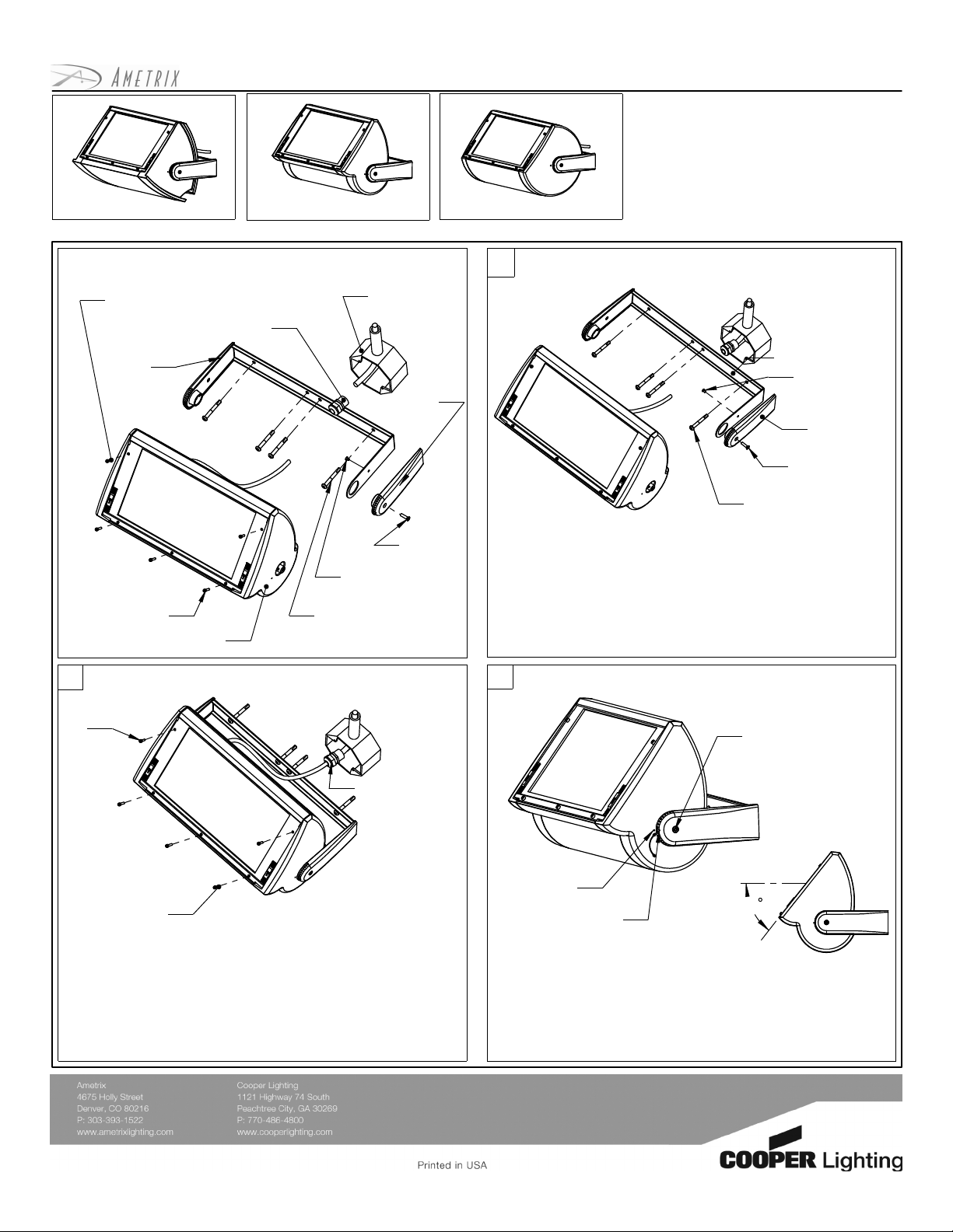
Exploded view and part call-out
#6-32 x 1/2
Socket cap screw
(x2)
Yoke
#6-32 x 5/8
Socket cap screw
(x3)
Fixture head
2
#6-32 x 1/2
Socket cap screw
(x2)
Outdoor J-box
1/2" Compression
fitting
1/4" Fasteners
(by others)
(by others)
Yoke end cap
#10-32 x1
End screw
#6-32 x 1/4
Screw (x2)
Wiring and sealing outdoor fixture
1
1. To secure yoke to outdoor surface, the fixture head must be
removed. First, remove both #10-32 x 5/8 end screws.
2. Remove one #6-32 x 1/4 screw to remove yoke end cap and
fixture head. Place both fixture head and yoke end cap in a
safe place.
3. With fixture head and yoke end cap safely stored, secure
yoke to outdoor surface using four(4) appropriate 1/4"
fasteners (by others).
3
Mounting yoke to outdoor surface
Yoke end cap
#6-32 x 1/4
screw(x2)
Yoke end cap
#10-32 x 5/8
End screw (x2)
1/4 Fasteners
(by others) (x4)
Aiming the fixture
#10-32 x 5/8
end screws
1/2" Compression
fitting
#6-32 x 5/8
Socket cap screw
(x3)
1. To seal fixture head, after installing lamp, all screws and
latches must be secured on door face. Holes above latches
receive the #6-32 x 1/2 socket cap screws. The center hole(s)
receive the longer #6-32 x 5/8 socket cap screw.
2. Slide 1/2" compression fitting down fixture head wire and
splice wit power feed, ensuring all connections are properly
matched. Seal 1/2" compression fitting to outdoor surface and
ensure a watertight seal.
ADY071447 Rev A (ECN070295)
Fixture head
indicator
40
Yoke arm indicator
1. To aim fixture, loosen both #10-32 x.625 end screws. When
the PointGrabTM system indicators are lined up, the slope
of the lens face is 40-degrees. Each subsequent notch is
an additional 10-degrees.
2. When the fixture head is adjusted to the desired angle, re tighten end screws to secure the position.
Page 2
Vault w/ visor
Lamp
These installation instructions are valid with the above Ametrix styles
C-Scroll w/ visor
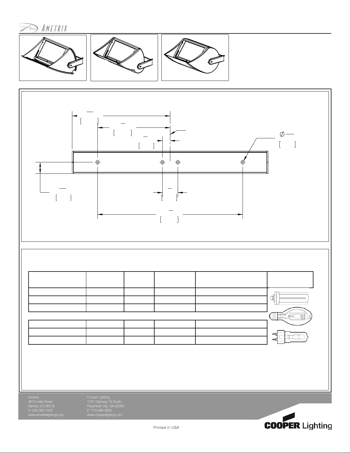
Mounting Plate Dimensions In [mm]
Mounting dimensions are for 16 1/2"(419.1mm) large YR indoor only
15
7
"
16
201.49
7
8
149.35
"5
5
"
8
15.88
Roundel w/ visor
C
L
Installation Instructions
Sheet 2 of 2
Large, OUTDOOR
YR (16.5")
(Yoke mount, Remote ballast)
Visor and Non-Visor
Warning
that all sources of power are turned off. All
work must meet local/national codes and be
performed by a certified electrician.
mount fixtures vertically.
: Before starting any work ensure
Do not
9
"
32
6.93
29
"
32
FIXTURE SIZE
(inches/ mm)
16
16
16
16
16
16
/ 419.1 32 W 1 T4 Compact Flourescent
1/2
/ 419.1 42 W 1 T4 Compact Flourescent
1/2
/ 419.1 57 W 1 T4 Compact Flourescent
1/2
/ 419.1 100 W 1 ED17 Ceramic Metal Halide
1/2
/ 419.1 150 W 1 T6 Ceramic Metal Halide
1/2
/ 419.1 175 W 1 ED17 Ceramic Metal Halide
1/2
WATTAGE
# OF
LAMPS
1
"1
4
31.7523.24
3
11
"
4
298.70
Lamping Size Chart
(lamps provided by others)
LAMP TYPE LAMP DESCRIPTION
(not to scale)
ADY071447 Rev A (ECN070295)
 Loading...