

Page 1
INSTALLATION INSTRUCTIONS AND OPERATING MANUAL
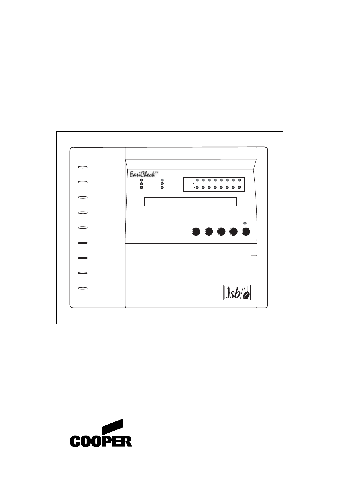
EASICHECK™ 1001
Self Contained
POWER ON
EMERGENCY
MODE
GENERAL FAULT
ADDRESSABLE EMERGENCY LIGHTING CONTROL PANEL
SYSTEM FAULT
TEST IN PROGRESS
DISABLE
LUMINAIRE
GROUPS
12345678
910111213141516
BUZZER
2
1
3
4 5
SCROLLMUTE
Lighting and Security
Page 2

CONTENTS
Introduction
Specification
The SCAEL Interface
Wiring
Powering Up
Commissioning
Setting Date/Time
User Menu
Networking
PC Software
2
EASICHECK™
Page 3

INDEX
Page
Contents 2
Index 3
1.0 Introduction 4
1.1 Specification 5
1.2 Features 6
SCAEL Interface
2.0 Programming 7
2.1 Installation 7
EasiCheck Panel
3.0 Installation 8
3.1 Installation guide 8
4.0 Loop Circuits 9
4.1 Isolators 9
4.2 Loop connection diagrams 10
5.0 Cable Requirement 11
5.1 Cable length - Volt drop 11
5.1.1 Spur circuit 11
5.1.2 Loop circuit 12
5.1.3 Loop with spurs 12
6.0 Mains Connection 14
6.1 Battery Connection 15
7.0 System Wiring 16
Optional Accessories
8.0 Network Diagram 17
8.1 Printer Connections 18
Panel Menu
9.0 Main Panel operations 19
9.1 Initial Power Up (Autolearn Mode)19
9.2 Commissioning 19
9.3 Setting Time and Date 20
9.4 Test Schedule 21
9.4.1 Weekly Test 21
9.4.2 Network Address 21
9.4.3 View Group Test 21
9.5 Menu Options 22
9.5.1 Enable/Disable All 22
9.5.2 Reset the Panel 23
9.5.3 Print Options 23
9.5.4 Discharge Test 24
9.5.5 Led Test (on the fitting) 25
9.5.6 V(Voltage) / I(Current) Display 25
9.6 User menu flowchart 26
Up/Downloading using PC Software
10.0 Description 27
10.1 Connection information 27
Miscellaneous
11.0 Site Configuration Forms 28
12.0 Group Testing 34
13.0 Weekly Test 34
14.0 Commissioning Request Form 35
3
EASICHECK™
Page 4
1.0 Introduction
The EASICHECK™ Panel is designed to periodically test the functionality of your installed
emergency. Once a week, once a month or 6 monthly, the EASICHECK™ will carry out tests
to determine whether your emergency lighting is fully functional.
For testing purposes, the luminaires can be designated to groups. The information for each
group is loaded at the commissioning stage via a PC. Groups can include luminaires in diverse
locations so as to prevent effective loss of emergency cover following test routines.
Manual tests with duration from 5 minutes to 3 hours can easily be instigated. Any faults that
are found are displayed at the panel. Multiple faults can be scrolled through the display by
pressing the scroll button. A permanent or intermittent fault will be detected by the panel. The
display will show the fault, address and location. The fitting will show flashing Amber LED
instead of the flashing green LED. The panel can test a single luminaire at any time if required.
This is done by use of the test mode menu option. A printer may be attached to record all test
results.
If the system communication fails, loop voltage is incorrect, or if there is a Mains failure, any
test that is in progress is terminated and the luminaire states are returned to normal mode.
4
EASICHECK™
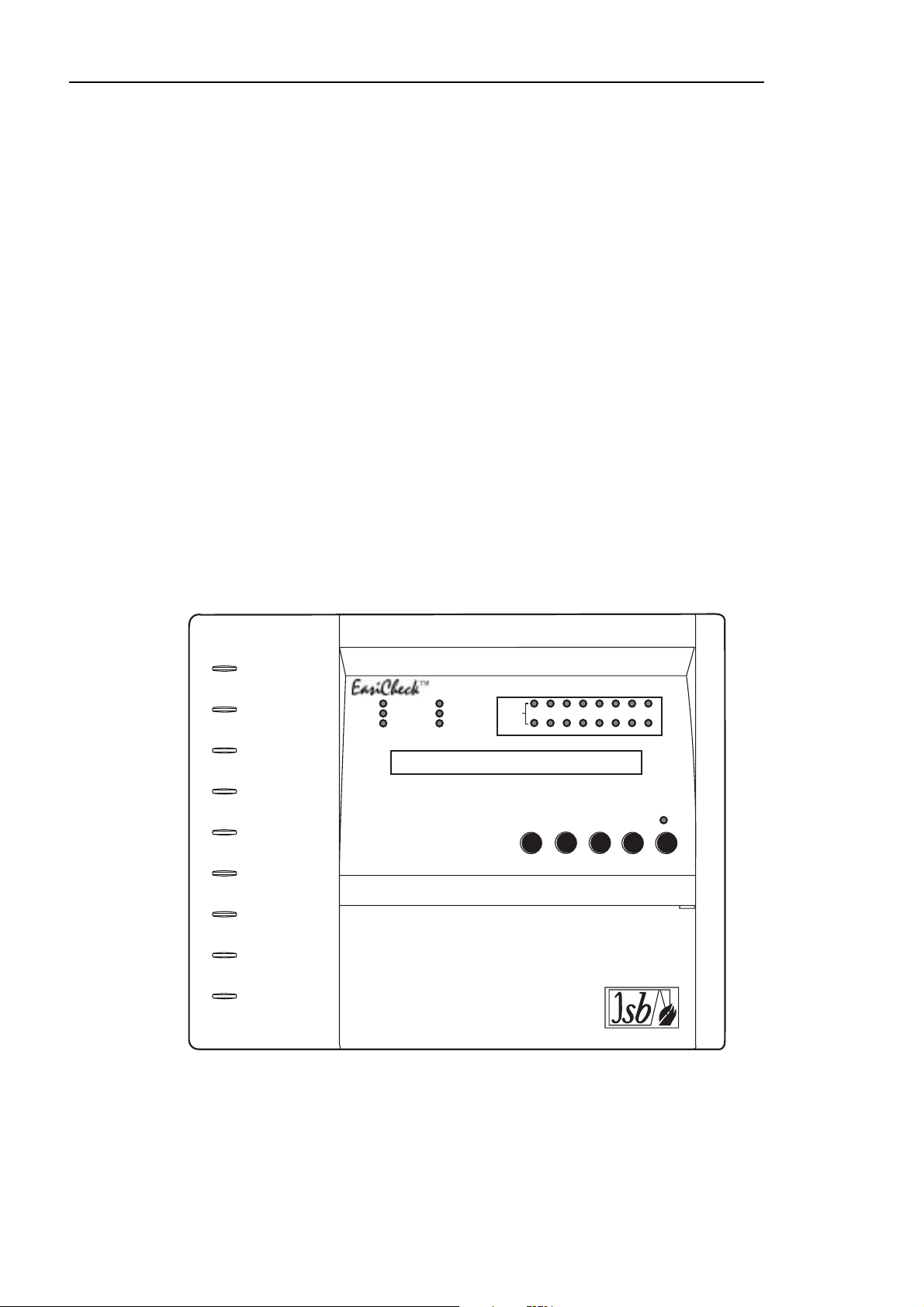
POWER ON
EMERGENCY
MODE
GENERAL FAULT
ADDRESSABLE EMERGENCY LIGHTING CONTROL PANEL
SYSTEM FAULT
TEST IN PROGRESS
DISABLE
LUMINAIRE
GROUPS
12345678
910111213141516
BUZZER
2
1
3
4 5
SCROLLMUTE
Page 5

1.1 Specification
" User Text Display Address, location and fault description.
" Dimensions H x W x D (mm) 270 x 332 x 90
" Maximum System Capacity 250 self contained luminaires depending on system type
" Weight (Including Battery) 6 Kg
" LED Indicators/LC Display LEDs are;
Power On, Emergency Mode, General
Fault, System Fault, Test In Progress, Disable,
Scroll and Luminaire Groups
LCD is 2 lines x 40 characters
" User Controls Soft touch five button keypad
" User Function Menu Enable/Disable Units/SCAEL Interface LED Test, Test Mode,
Voltage/Current Display and Print options using RS232
Portable Printer
" Remote Signal Volt free change over Contact (1A 24V DC Relay)
" Communications Port RS232 (Printer) and RS485 (Repeater)
" Sealed Lead Acid Batteries 24V system comprising of 2 x 12V @ 3.2Ah each
" Battery Charger 800mA, constant voltage, temperature compensated
" Loop Output 26V Stabilised
" Loop Communication 9V pulses superimposed on the 26V line
" Temperature Range Battery charger compensated 0° to 40°(C
" Commissioning Site Software Download at initialisation from a PC
" Memory life(without power) 10 Years
" Working Memory 1 week for test result information
" Number of Loops 1
5
EASICHECK™
Page 6

1.2 Features
" 80 Character display showing the exact address and location of any fault identified.
" 16 group capability with individual group indicators in addition to text display.
" One loop giving a total of 250 address capacity.
" Two self contained 12 volt rechargeable batteries for 6 hour standby with a fully loaded loop.
" Full text downloading in seconds using PC compatible computer (i.e. Laptop).
" Self learning of SCAEL Interfaces addresses to aid commissioning
" In the event of Fault, display shows location text, address, charge current and battery voltage.
" Stabilised 24V output independent of Battery voltage during Mains fail.
Fault Relay
Volt free change over contact is provided (see section 7.0), it is rated at 1A / 24V DC
The relay operates upon any Fault condition.
Loop Wiring
Electrical insulation test should not be carried out if the loop cables are connected to the
EasiCheck panel, or to the fittings or to any electronic circuitry.
Before connecting the wiring to the EasiCheck panel, the wiring should be tested for continuity,
polarity, short circuit and earth faults.
Networking
A maximum of 64 EasiCheck Panels can be networked by fitting of additional network cards.
The Panels are inter connected in a network loop (two in, two out). Any EasiCheck Panel
reporting a fault in the system will be shown on all Panels. The Fault may be viewed and reset
from any Panel. See page 11 for cable type
6
EASICHECK™
Page 7
2.0 Programming the EASICHECK™ SCAEL Interface.
Before the SCAEL Interface is connected it must be programmed in order for the
EASICHECK™ Panel to recognise it as part of the system. This is done with an
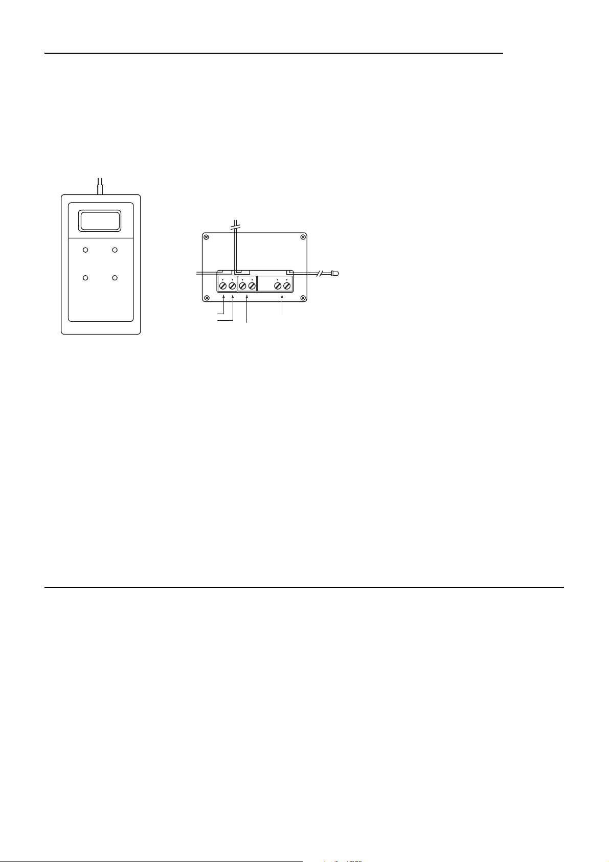
EASICHECK™ hand held programming unit. The programming unit has two spring loaded
connections which are to be held briefly on to the SCAEL Interface ‘TELE/LOOP’ connections.
See Diagram;
Programmer SCAEL INTERFACE
Switch on the programming unit by pressing the top right button marked On/Off. After a few
seconds the programming unit display will show the next address number due to be
programmed. Hold the spring terminal against the SCAEL Interface and press Program. The
programmer will show ‘Pro’ to register address acceptance and then the address number will
increment by one ready for the next interface. The interface is now ready to be fitted. Repeat
this until all of the interfaces have been programmed.
Note: If you are unsure as to which address the SCAEL Interface has been programmed for,
then with the programmer switched off, hold the spring terminals against the SCAEL Interface
and switch on the programmer. After a short delay the programmer display will flash the
number of the SCAEL Interface address and then return to the next address number to be
programmed.
The SCAEL unit contains a latching relay. During transit it is possible for the relay to change
state, even though it is not powered up. During programming the programmer will
automatically restore the relay to its correct position.
2.1 Installation of the SCAEL Interface.
The SCAEL Interface should be connected into the Luminaire by following the instructions
supplied.
Attach the address label to the Luminaire. Sets of address labels are available separately.
The interface is connected in series with the existing battery pack and the LED is fitted through
a hole in the gear tray to display healthy or fault status. The incoming mains live charge and
live switched (maintained luminaires only) should be wired into the screw terminal block and
the corresponding flying wires for each should be connected into the luminaires in the usual
manner.
The interface continually monitors the battery voltage and charge current which is interrogated
by the EASICHECK™ Control Panel and checked for correctness. Any luminaire found to be
incorrect will have it’s Green LED switched to Amber and the Control Panel will display the
Address number, location and a fault description.
7
EASICHECK™
BATTERY OUT
RED = +VE
001
BLACK = -VE
PROGRAM ON / OFF
TENS
UNITS
LIVE SWITCH (OUT)
LIVE CHARGE (OUT)
BROWN
LIVE SWITCH (IN)
LIVE CHARGE (IN)
SCAEL INTERFACE
RED
LED
TELE/LOOP
BATTERY IN
Page 8

3.0 Installation
In common with all electronic equipment the panel should be installed in a clean, dry,
reasonably well ventilated place, and not in direct sunlight. Temperatures in excess of 40°(C
and below 5°(C may cause problems, if in doubt consult Cooper Lighting and Security Ltd. The
panel should be located away from any potential hazard, in a position where it is readily
accessible to authorised staff. Mount the panel to the wall using the drill template provided. Do
not drill through the panel to the wall as dust will contaminate the circuitry, and prevent correct
operation.
A metal back box is available for semi-recessing the control panel. Dimensions 327mm wide x
265mm high x 77mm deep.
When using 20mm conduit entry direct to the top of the housing, use a flanged coupler to
ensure a wide distribution of pressure when tightening the coupling.
3.1 Installation Guide
Never Use oversized conductors or connect more conductors into termination
points than it can safely contain.
Never Carry out insulation tests on cables connected to electronic equipment.
Always Use the correct gauge of cables.
Always Adhere to volt drop limitation for loop cables
8
EASICHECK™
Page 9
4.0 Loop Circuits
The following recommendations apply specifically to EASICHECK™ loop circuits:
" The EASICHECK™ Panel is a one loop Addressable emergency lighting test system.
" The loop circuit has provision for a maximum of 250 SCAEL Interfaces.
" Each SCAEL Interface has it’s own individual address which can be programmed by
using the EASICHECK™ programmer.
" The recommended cable should be used for the loop circuit.
(see Cable Types section)
" The total length of cable in the loop circuit should not exceed 2km (including all spurs)
" Since SCAEL Interfaces receive/send signals in either direction, a complete loop or
ring circuit is preferred (see diagram) so they continue to function if an open circuit
occurs.
" Isolator units can be installed at intervals throughout the circuit to prevent a short circuit
fault disabling the complete loop.
" It is important to check the voltage drop to ensure the supply to any SCAEL Interface
does not fall below 15V DC.
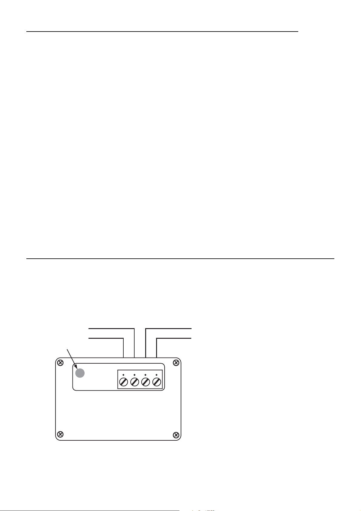
4.1 Isolators
For spur circuits, it is preferable for circuit integrity to fit an isolator at each spur. For loop
circuits it is preferable to fit an isolator every 15 to 20 fittings
9
EASICHECK™
Note: Unlike the SCAEL Interfaces,
the loop polarity must be observed.
TELE/LOOP
+
-
Fault Indicator
LOOP WIRING
+
-
+
-
-
+
ISOLATOR
PART No: 7466-0005
4063.100.000
Page 10
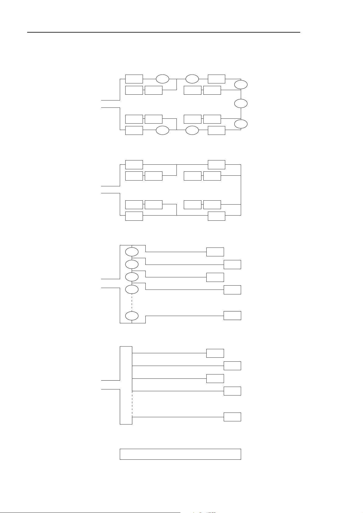
4.2 Loop connection diagrams
10
EASICHECK™
Mixed Loops with Spurs (+ Isolators)
Loop
Loop
S S
S S S S
S S S S
S S
Mixed Loops with Spurs (No Isolators)
S S
S S S S
S S S S
S S
I
I I
I
Radial (+ Isolators)
I
S
I
I
I
Loop
Loop
I
I
I
I
Radial (No Isolators)
S
S
S
S
S
S
S
S
S
I = Isolator, S = SCAEL Interface
Page 11

5.0 Cable Requirement
Cable type : Two core or screened
Recommended size : 1.0 to 2.5mm2(see Volt drop calculation)
Maximum Resistance : 40 Ohms
Maximum Capacitance : 2.0 µF / km
Maximum cable length : 2 km (see Volt drop calculation)
5.1 Cable Length - Voltage drop
5.1.1 Spur Circuit.
Make sure that the minimum voltage at the furthest point of the spur exceeds 15 Volts
alternatively the maximum voltage drop on the cable should be less than 10 Volts.
Calculation for Voltage Drop
Vdrop = R x I x n (Volts) (1)
Re-arranged equation (1)
R = Vdrop/I x n Ω (2)
n= Number of fittings or addressable interfaces on the spur
I = Average Current of an addressable interface in the fitting = 0.0012 Amps
R = Cable cold resistance ( go and return) Ω
Vdrop not to exceed 10 Volts
This resistance will vary depending on the size of the cable as shown below;
Table 1.0
Therefore for worst case condition, the maximum cable resistance R (max) is;
R(max) = 10/ I x n = 10/0.0012 x n = 8333.33/n Ω (3)
Example 1 If a spur has 250 fittings , using equation (3) the maximum cable resistance is.
R(max) = 8333.33/250 = 33.3 Ω
11
EASICHECK™
Size Cold Resistance Cold Resistance
Single Core Go and Return
1.0 mm
2
18.1 Ω/km 36.2 Ω/km
1.5 mm
2
12.1 Ω/km 24.2 Ω/km
2.5 mm
2
7.4 Ω/km 14.8 Ω/km
Page 12

Example 2 If the spur is wired with 1.0 mm
2
cable, using the go and return column of
table 1, the Max cable length will be 33.3/36.2= 0.9 Km , for 1.5 mm2the Max
cable length is 33.3/24.2 = 1.38 Km and finally for 2.5 mm2the cable length is
33.3/14.8= 2.25 Km.
5.1.2 Loop Circuit;
Calculation as above but assume the loop is broken at one end.
5.1.3 Loop with spurs;
Calculate all individual spurs including maximum return to Panel.
Example 3
As the above example with 250 fittings and using 10 spurs, each having 25
fittings with a main loop length of 100 Metres as shown in Fig1.
Assuming worse case with all load lumped in one place, the maximum
distance of each spur using (Equation 1) will be;
Vdrop = [ RL x n x I ] x [ Rspur x ns x nfs I ] (4)
Where RL = Main Loop cable resistance as shown on Fig 1.
n= Total number of fittings on the loop.
I= Average current of an addressable interface = 0.0012 A
Rspur = Spur resistance
ns = Total number of spurs
nfs = Total number of fittings per spur
Re-arrange (Equation 4) so that the spur resistance is;
Rspur = [ Vdrop - [ RL x n x I ] ] Ω (5)
ns x nfs x I
12
EASICHECK™
Page 13

a) If the loop and spurs are wired with 1.0mm2cable and allowing for maximum permissible
voltage drop with reference to table 1;
Rspur = [ 10 - [ 3.62 x 250 x 0.0012 ] ] (6)
10 x 25 x 0.0012
This corresponds to a maximum spur cable length of 0.820 km
Hence, the total system cable length is 8.3km compared to 0.9 km for a loop system
(see example 2)
b) Similarly, if the system is wired using 1.5mm
2
cable and following the above rules;
Rspur = 30.9Ω , This corresponds to a maximum spur cable length of 1.27km
Hence, the total system cable length is 12.8 km compared to 1.38 km for a loop system
(see example 2)
13
EASICHECK™
= 29.7Ω
Fig. 1
Panel
RI = Cable resistance of main loop
nfs
Loop
of
100m
Number of spurs (ns)
Fitting
Page 14

6.0 Mains Connection
" Normal supply for the system should be derived from the public supply system.
" When no public supply is available, privately generated power may be used.
" The standby battery provides 3.2Ah which will maintain the system in operation for at
least 6 hours upon a Mains failure.
The EASICHECK™ draws a maximum of 1 Amp from the 230V mains supply, wiring used
should be adequate for this load, and should be marked
‘EMERGENCY LIGHT SYSTEM, DO NOT SWITCH OFF’.
A plug and socket is not satisfactory. The mains supply should be connected only to the
terminal block marked ‘230V’, this can be found on the top left hand side of the power supply
board.
14
EASICHECK™
Note: Using a switched DPST spur provides a method of isolating the Mains supply for
maintenance purposes.
230-240 VAC
Mains
LNE
Page 15

6.1 Battery Connection
The two 12V Batteries are connected together in series. The Red wire from the EasiCheck is
connected to the Red terminal of one of the Batteries, the link wire is then fitted to the Black
terminal of that Battery, the other end of the link wire is fitted to the Red terminal of the other
Battery, then finally the Black wire from the EasiCheck is connected to the unconnected Black
Battery terminal.
15
EASICHECK™
(+VE)
+-
Black(-VE)
Red
BlackRed
(+VE)
(-VE)
Page 16

7.0 System Wiring
Connect all SCAEL Interfaces to the EASICHECK™ Panel by means of the TELE/LOOP
connections. There are two connections (loop in & out on +). Interfaces are not polarity
sensitive;
16
EASICHECK™
230 VAC
Mains
LNE
PG
I/P
REPEATER
CONNECTION
Tx- Tx+
FAULT
RELAY
N/O N/CC0V TxD
26V
RS232
RS232 PRINTER
0V
RxDTxD
F+ S-
F-
LOOP
S+
Page 17

Optional Accessories
8.0 Networking
The EASICHECK™ can be fitted with an optional Network card for which there is already a
reserved socket. This is a PCB that simply plugs on to the Power Supply Board and has four
connections. These four connections wire to other Panels fitted with Network cards in a loop
configuration (two in, two out). All Panels connected in this manner will be fully operational and
any Panel will control the system from its keypad. Once a network card has been fitted it’s
address number must be set.
17
EASICHECK™
Network interconnections;
Network Card;
Network sample wiring;
JP1
IN OUT
+ - + -
JP2
Panel 1 Panel 2 Panel 3
NETWORK CARD
+ - + -
IN OUT
+ - + -
IN OUT
EasiCheck™
Panel
EasiCheck™
Panel
2 Core
+ - + -
IN OUT
EasiCheck™
Panel
EasiCheck™
Panel
Page 18

8.1 Printer Connections.
18
EASICHECK™
The Printer enables the user to printout Weekly test reports, Full Reports and the Event Log as needed.
Printer
PSU
Connection
Black wire
FAULT
RELAY
N/CCN/O
RS485
Tx-
Tx+0VTxD
RS232 RS232
PRTR
TxD
RxD
0V
Panel connections
Page 19

9.0 Main Panel Operation
There are two modes of operation;
1. Autolearn mode; System automatically searches for all SCAEL Interfaces connected to
the loop.
No text is available in this mode. This mode can be used for initial checking.
(Note: SCAEL Interfaces must be programmed)
2. Commissioned Mode; The Panel is re-commissioned using a PC to download Address,
Group, type of luminaire, Number of Cells, Duration, Descriptive address text for each
fitting and Test times.
9.1 Initial Power Up (Autolearn Mode)
Switch Mains power on and connect Batteries
After an initial test the display will show;
At this point the system is checking to see how many SCAEL Interfaces are connected.
After a short period the display will show for example;
The system is now ready for limited use without descriptive text for the location.
9.2 Commissioning
In order for the display to show user chosen specific text, the Panel must be Commissioned by
a Cooper Lighting and Security Service Engineer using a PC to download the required
descriptive text;
To Re-Commission, enter the Engineer Passcode.
The display will show;
Press (, the display shows;
Press &, the display shows;
Press &.
The display will light all LEDs in turn and then the display will show;
Press &, the display will show;
See Downloading section (Page 25)
19
EASICHECK™
WAITING FOR THE MASTER TO TRANSMIT THE
NUMBER OF FITTINGS INSTALLED
SYSTEM HEALTHY ! No of FITTINGS= 198
DATE : dd/mm/yy TIME : 10:07:58
1: TIME 2: DATE 3:TEST SCHEDULE
4: RE-COMMISSION 5: QUIT
ARE YOU SURE YOU WANT TO RE-COMMISSION ?
PRESS 1 FOR YES PRESS 5 FOR NO
ATTENTION !!! THIS WILL ERASE ALL DATA !
PRESS 1 FOR CONTINUE PRESS 5 FOR ABORT
TRANSMIT TEXT WITH PC PRESS 1
NO TEXT AVAILABLE PRESS 2
PLUG PC INTERFACE UNIT INTO THE EASICHECK
WITH PC READY TO TRANSMIT
Page 20

9.3 Setting the Time & Date
Setting The Time;
Enter the Engineer Passcode.
The display will show;
Press &, the display will show;
Press &,%,$ or ( to adjust the current time.
Upon completion, press ' to exit the menu.
Setting The Date;
Enter the Engineer Passcode.
The display will show;
Press %, the display will show;
Press &,%,$ or ( to adjust the current date.
Upon completion, press ' to exit the menu.
20
EASICHECK™
1:TIME 2:DATE 3:TEST SCHEDULE
4:RE-COMMISSION 5: QUIT
TIME = HH:MM:SS TO UPDATE PRESS
1:SECS 2:MIN 3:HOUR 4:TENS 5:QUIT
1:TIME 2:DATE 3:TEST SCHEDULE
4:RE-COMMISSION 5: QUIT
DATE = DD/MM/YY DAY OF WEEK: THURSDAY
1:DAY 2:MONTH 3:YEAR 4:D.O.W 5:QUIT
Page 21

21
9.4 Test Schedule
Enter the Engineer Passcode.
The display will show;
Press $, the display will show;
Note: After each menu has been accessed, the passcode will have to be re-entered
9.4.1 Weekly Test;
Press &, the display will show;
Press &,%,$ or ( to adjust the test day and time.
Once the time has been corrected, press ' to exit the menu.
9.4.2 Network Address;
Press %, the display will show;
Press & or % to adjust the network address. (Set to 000 if No Network card is fitted)
Once the address has been selected, press ' to exit the menu.
9.4.3 View Group Test;
Press $, the display will show;
Press ' to exit the menu.
1:TIME 2:DATE 3:TEST SCHEDULE
4:RE-COMMISSION 5: QUIT
1:WEEKLY TEST 2:NETWORK ADDRESS
3:VIEW GROUP TEST 5:QUIT
NETWORK ADDRESS IS : 032
1:TENS 2:UNITS 5:QUIT
WEEKLY TEST SET : TUESDAY AT 22.00 HRS
1:DATE 2:HOUR 3:TENS 4:UNITS 5:QUIT
SYSTEM IN AUTO-LEARN MODE!! ALLTESTING
IS INITIATED MANUALLY 5:QUIT
Page 22

22
9.5 User Menu Options
Enable/Disable (Fittings);
Enter the User Passcode.
The display shows;
Press &, the display shows;
Press & or %, the display shows;
Press % and $ to select the required fitting then press & to enable/disable it.
The display shows;
Repeat pressing % and $ if further fittings require enabling/disabling.
Press ' to exit the menu.
9.5.1 Enable / Disable All;
Enter the User Passcode.
The display will show;
Press &, the display shows;
Press % or $, the display shows;
Note: If Disable is selected, the disable LED illuminates and buzzer sounds once.
CODE ACCEPTED. 1:ENABLE/DISABLE
2:RESET 3:OTHERS 4:TEST 5:QUIT
1:ENABLE 2:DISABLE 3:DISABLE ALL
4:ENABLE ALL 5: QUIT
TO ENABLE/DISABLE FITTING ### (PRESS 1)
2:HUNDREDS 3:UNITS 4:UNITS 5:QUIT
FITTING ### IS ENABLED/DISABLED
2:HUNDREDS 3:TENS 4:UNITS 5:QUIT
CODE ACCEPTED. 1:ENABLE/DISABLE
2:RESET 3:OTHERS 4:TEST 5:QUIT
1:ENABLE/DISABLE 2:ENABLE ALL
3:DISABLE ALL 5:QUIT
ALL FITTINGS IN THE LOOP ARE ENABLED/DISABLED
EXIT (PRESS 5)
Page 23

23
User Menu Options continued...
9.5.2 Reset the Panel;
Enter the User Passcode.
The display will show;
Press %, the display shows;
All LEDs light up in turn and then switch off.
The Panel returns to normal.
9.5.3 Print Options;
Enter the User Passcode.
The display will show;
Press $ the display shows;
Press $ the display shows;
Ensure that the printer is connected and switched on.
press &,%,$ or (, the selected printout will be generated.
CODE ACCEPTED. 1:ENABLE/DISABLE
2:RESET 3:OTHERS 4:TEST 5:QUIT
RESET ACTIVATED
CODE ACCEPTED. 1:ENABLE/DISABLE
2:RESET 3:OTHERS 4:TEST 5:QUIT
1:V/I READINGS 2:LED TEST
3:PRINT 5:QUIT
1:FITTING STATUS 2:WEEKLY TEST RESULT
3:FULL DISCHARGE TEST 4:EVENT 5:QUIT
Example Event Log
--------------------------------
COOPER LIGHTING !! EASICHECK
DATE : 07/05/02
TIME : 10:07:58
--------------------------------
EVENT LOG
-----FAULT EASICHECK PANEL------
CHARGER !!! CHECK BATTERY/MAINS
DATE : 07/05/02 TIME : 10:06:00
--------------------------------
-------------FAULT--------------
LAMP ADD:001 V=03.82 I=0.11
DATE : 07/05/02 TIME : 10:04:33
-----FAULT EASICHECK PANEL------
SYSTEM REBOOT !!
DATE : 07/05/02 TIME : 09:59:43
--------------------------------
Weekly Test Result
-------------------------------COOPER LIGHTING !! EASICHECK
DATE : 07/05/02
TIME : 10:07:58
-------------------------------TEST RESULT !!! WEEKLY TEST AT
DATE : 07/05/02 TIME : 09:55:59
-------------------------------ADD GP CELLS DUR V I
001 01 --- -- 03.65 -1.07
--------------------------------
Page 24

User Menu Options continued...
9.5.4 Discharge Test;
Enter the User Passcode.
The display will show;
Press (, the display shows;
Press &, the display shows;
Press &, % or $, the display shows;
If & is selected, the panel returns to normal display and starts test.
If % is selected, the display shows;
Press % or $ to select the required address number.
Press &, the display shows;
Press % or $ to select another fitting then press & to test.
Press ' to return to normal.
If $ is selected, the display shows;
Press % or $ to select the required group.
Press &, the display shows;
Press % or $ to select another group.
Press ' to return to normal.
24
EASICHECK™
CODE ACCEPTED. 1:ENABLE/DISABLE
2:RESET 3:OTHERS 4:TEST 5:QUIT
1:DISCHARGE TEST 2:ALL IN CHARGE
5:QUIT
DURATION OF TEST !! 1: FIVE MINUTES
2: ONE HOUR 3: THREE HOURS 5:QUIT
DO YOU WANT TO TEST 1: ALLFITTINGS
2: SINGLE FITTING 3: GROUPS 5:QUIT
TO TEST FITTING ### (PRESS 1)
2: HUNDREDS 3:TENS 4:UNITS 5:QUIT
TESTING FITTING ### FOR MORE PRESS
2: HUNDREDS 3:TENS 4:UNITS 5:QUIT
TESTING GROUP ### FOR MORE PRESS
UP: 2 DOWN: 3 QUIT : 5
TO TEST GROUP # !! PRESS 1 FOR YES
UP: 2 DOWN: 3 QUIT : 5
Page 25

User Menu Options continued...
9.5.5 LED Test (on the fitting)
Enter the User Passcode.
The display will show;
Press $, the display shows;
Press %, the display shows;
Press & or % the LED changes colour.
Press ' to return to normal.
9.5.6 V(Voltage) / I(Current) Display;
Enter the User Passcode.
The display will show;
Press $, the display shows;
Press &, the display shows;
Press % or $, to select;
Press &, the display shows;
After a short while, the display shows;
Press ' to return to normal.
25
EASICHECK™
CODE ACCEPTED. 1:ENABLE/DISABLE
2:RESET 3:OTHERS 4:TEST 5:QUIT
1:V/I READINGS 2:LED TEST
3:PRINT 5: QUIT
1:TEST LED AMBER
2:LED NORMAL GREEN 5:QUIT
CODE ACCEPTED. 1:ENABLE/DISABLE
2:RESET 3:OTHERS 4:TEST 5:QUIT
1:V/I READINGS 2:LED TEST
3:PRINT 5: QUIT
TO SELECT FITTING ### (PRESS 1)
2:HUNDREDS 3:TENS 4:UNITS 5:QUIT
THE BATTERY V AND I OF ADD: ###
WILL BE DISPLAYED IN AMOMENT
BATTERY VOLTAGE AND CURRENT OF ADD: ###
VOLT = 04.04 CURR = +0.21 QUIT (PRESS 5)
Page 26

9.6 User menu flowchart
EASICHECK™ Control Panel
User Menu Structure
Self-Contained
26
EASICHECK™
NOTE: During fault conditions the buzzer
may be muted by pressing button 4>
Multiple faults may be viewed by pressing
button 5 only when the scroll Led is flashing.
1 ENABLE
2 DISABLE
3 DISABLE ALL
4 ENABLE ALL
5 QUIT
1 ENABLE
2 HUNDREDS
3 TENS
4 UNITS
5 QUIT
1 DISABLE
2 HUNDREDS
3 TENS
4 UNITS
5 QUIT
USER
PASSCODE
1 ENABLE/DIS
2 RESET
3 OTHER
4 TEST
5 QUIT
1V/I READINGS
2 LED TEST
3 PRINT
5 QUIT
1 DISCHARGE
2 ALL CHARGE
5 QUIT
1 SELECT
2 HUNDREDS
3 TENS
4 UNITS
5 QUIT
1 AMBER
2 GREEN
5 QUIT
1 FIT STATUS
2 WEEKLY TEST
3 FULL DIS
4 EVENT
5 QUIT
1 FIVE MINS
2 ONE HOUR
3 THREE HOUR
5 QUIT
1 LAST 10
2 ALL EVENTS
3 CLEAR LOG
5 QUIT
1 ALL FITTINGS
2 SINGLE
3 GROUPS
5 QUIT
1 TEST
2 HUNDREDS
3 TENS
4 UNITS
5 QUIT
1 TEST
2 UP
3 DOWN
5 QUIT
Page 27

10.0 Up/Downloading using PC Software (Commissioning Engineer Operation)
The PC software enables the address, location text, luminaire type and any comments to be
downloaded to the EASICHECK™ Panel. Each luminaire can be assigned to a group for
testing purposes.
The software can download to all 64 networkable Panels.
The PC is connected to each Panel on the network in turn. All data for that Panel is
downloaded.
The PC software allows copying of Group or Panel for cases where a floor or level has been
copied.
Site details on screen include full postal address, post code, telephone number etc. And any
additional remarks.
The testing schedule can be set from a pre-set menu or a custom setting.
For networked systems, panels are identified by panel number, P1, P2 etc.
10.1 Connection Information
27
#
POWER ON
EMERGENCY
MODE
GENERAL FAULT
ADDRESSABLE EMERGENCY LIGHTING CONTROL PANEL
SYSTEM FAULT
LUMINAIRE
TEST IN PROGRESS
GROUPS
DISABLE
PLUG PC INTERFACE UNIT INTO THE
EASICHECK WITH PC READY TO TRANSMIT
12345678
910111213141516
BUZZER
2
1
3
4 5
SCROLLMUTE
Page 28

28
Site Configuration.
Address Group Type Area/Location Comment
1
2
3
4
5
6
7
8
9
10
11
12
13
14
15
16
17
18
19
20
21
22
23
24
25
26
27
28
29
30
31
32
33
34
35
36
37
38
39
40
Page 29

Site Configuration continued.
29
EASICHECK™
Address Group Type Area/Location Comment
41
42
43
44
45
46
47
48
49
50
51
52
53
54
55
56
57
58
59
60
61
62
63
64
65
66
67
68
69
70
71
72
73
74
75
76
77
78
79
80
Page 30

30
Site Configuration continued.
Address Group Type Area/Location Comment
81
82
83
84
85
86
87
88
89
90
91
92
93
94
95
96
97
98
99
100
101
102
103
104
105
106
107
108
109
110
111
112
113
114
115
116
117
118
119
120
Page 31

Site Configuration continued.
31
EASICHECK™
Address Group Type Area/Location Comment
121
122
123
124
125
126
127
128
129
130
131
132
133
134
135
136
137
138
139
140
141
142
143
144
145
146
147
148
149
150
151
152
153
154
155
156
157
158
159
160
Page 32

Site Configuration continued.
32
EASICHECK™
Address Group Type Area/Location Comment
161
162
163
164
165
166
167
168
169
170
171
172
173
174
175
176
177
178
179
180
181
182
183
184
185
186
187
188
189
190
191
192
193
194
195
196
197
198
199
200
Page 33

Site Configuration continued.
33
EASICHECK™
Address Group Type Area/Location Comment
201
202
203
204
205
206
207
208
209
210
211
212
213
214
215
216
217
218
219
220
221
222
223
224
225
226
227
228
229
230
231
232
233
234
235
236
237
238
239
240
Page 34

Site Configuration continued.
12.0 Group Testing
13.0 Weekly Test
34
EASICHECK™
Address Group Type Area/Location Comment
241
242
243
244
245
246
247
248
249
250
Group Time Day Month
1
2
3
4
5
6
7
8
9
10
11
12
13
14
15
16
Time
Day Of Week
Page 35

4.0 EasiCheck Commissioning Request Form
Project Title: ________________________________________
Prior to the commissioning being undertaken, it is necessary that the contractor completes the
following information so as to aid system commissioning.
With reference to the above project we confirm;
Dedicated Mains Supply Installed Yes / No
All Fittings Installed Yes / No
All Fittings Addressed Correctly Yes / No
Schematics and Drawings Available Yes / No
Wiring Fault Free Yes / No
Loop +ve to Earth _______MΩ -ve to Earth _______ M Ω
Note: Typical readings should show infinity to Earth with a minimum of 1 M Ω.
Please Schedule;
Installation/Address Inspection week commencing: ___ / ___ / ___
(1 weeks notice required)
System Commissioning week commencing: ___ / ___ / ___
(2 weeks notice required)
Reference should be made to the Project Plan Flowchart for timing of deliveries and
commissioning requests.
Upon receipt of this form, the confirmation requested for commissioning dates will be returned
to you. Failure to complete may delay system commissioning.
Signed on behalf of Contractor :
Above in Capitals :
Position :
Telephone Number :
Once completed, please return to;
Service Department
Cooper Lighting and Security Ltd
Wheatley Hall Road
Doncaster
South Yourkshire
DN2 4NB
TEL: 01302 321541
35
EASICHECK™
Page 36

www.cooper-ls.com
Cooper Lighting and Security Ltd.
Wheatley Hall Road, Doncaster, South Yorkshire, DN2 4NB, United Kingdom
Sales General Export
Tel: +44 (0)1302 - 303222 +44 (0)1302 - 321541 +44 (0)1302 - 303250
Fax: +44 (0)1302 - 367155 +44 (0)1302 - 303220 +44 (0)1302 - 303251
Email: sales@cooper-ls.com technical@cooper-ls.com export@cooper-ls.com
7702-4022/V1
Lighting and Security
 Loading...