

Page 1

66
WTM 502
QUICK-CHECK TENSION METER
USER’S GUIDE
http://www.cooperinstruments.com
TEL (540) 349-4746 • FAX (540) 347-4755
Page 2

TABLE OF CONTENTS
1.0 INTRODUCTION ............................................................................................1
1.1 Unpacking.............................................................................................................. 1
1.2 Description ............................................................................................................1
1.21 Front Panel and Keys...................................................................................... 2
1.3 Important features................................................................................................. 2
2.0 OPERATION...................................................................................................2
2.1 Typical Operation..................................................................................................2
2.2 Measurement Practices ........................................................................................ 4
2.3 Softkey Functions ................................................................................................. 4
2.31 Top Level Softkeys...................................................................................... 5
3.0 CONFIGURATION MODE..............................................................................7
3.1 Accessing the Configuration Mode..................................................................... 7
4.0 CHANGING SHEAVES ..................................................................................9
5.0 ACHIEVING BEST ACCURACY ..................................................................10
5.1 Accuracy.............................................................................................................. 10
5.2 Calibration to Specific Wire Type ......................................................................10
5.3 Loading Error ......................................................................................................11
5.4 Non-repeatability................................................................................................. 11
5.5 Non-linearity ........................................................................................................11
5.6 Wire Characteristics ...........................................................................................11
6.0 TROUBLESHOOTING .................................................................................11
7.0 SPECIFICATIONS........................................................................................12
8.0 WARRANTY REPAIR POLICY ....................................................................13
LIMITED WARRANTY ON PRODUCTS ...................... Error! Bookmark not defined.
OBTAINING SERVICE UNDER WARRANTY.............. Error! Bookmark not defined.
REPAIR WARRANTY................................................... Error! Bookmark not defined.
CF142 ii V 08/09/05
Page 3
1.0 INTRODUCTION
= Tip
= Remember
With its battery-powered electronic interface, setup and operation is made simple with on-screen prompts.
This manual covers the following:
• Unpacking
• Setup
• Operation
• Maintenance
• Troubleshooting
1.1 Unpacking
When you receive your WTM 502, unpack it and inspect the container and the instrument for any
damage. Report any problems to the shipping company immediately and save the packing materials.
Insert 2 AA batteries into the battery compartment, shown in Figure 1. Your WTM 502 probably comes
from the factory with the proper sheave size installed and calibrated for your application. If not, follow the
setup directions later in section 3.0 configuration Mode and 4.0 Changing Sheaves.
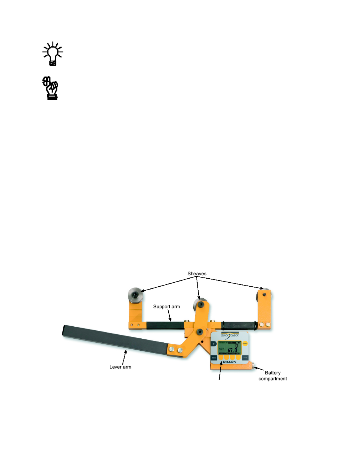
1.2 Description
This manual covers the setup and operation of the WTM 502 Clamp Line
Tensionmeter from Cooper Instruments. The WTM 502 is a simple,
accurate strand dynamometer. It is can be clamped onto a cable, accurately
determine the wire tension and be removed in seconds.
The WTM 502 can handle multiple wire diameters, it can display live
tension, dual live/peak tension, average tension captured from several
tests, dual tension/temperature display and a check-tensioning graphical
display.
The WTM 502 is shown in Figure 1 with the parts labeled.
FIGURE 1. WTM 502 PARTS
CF 142 1 V 08/09/05
Page 4
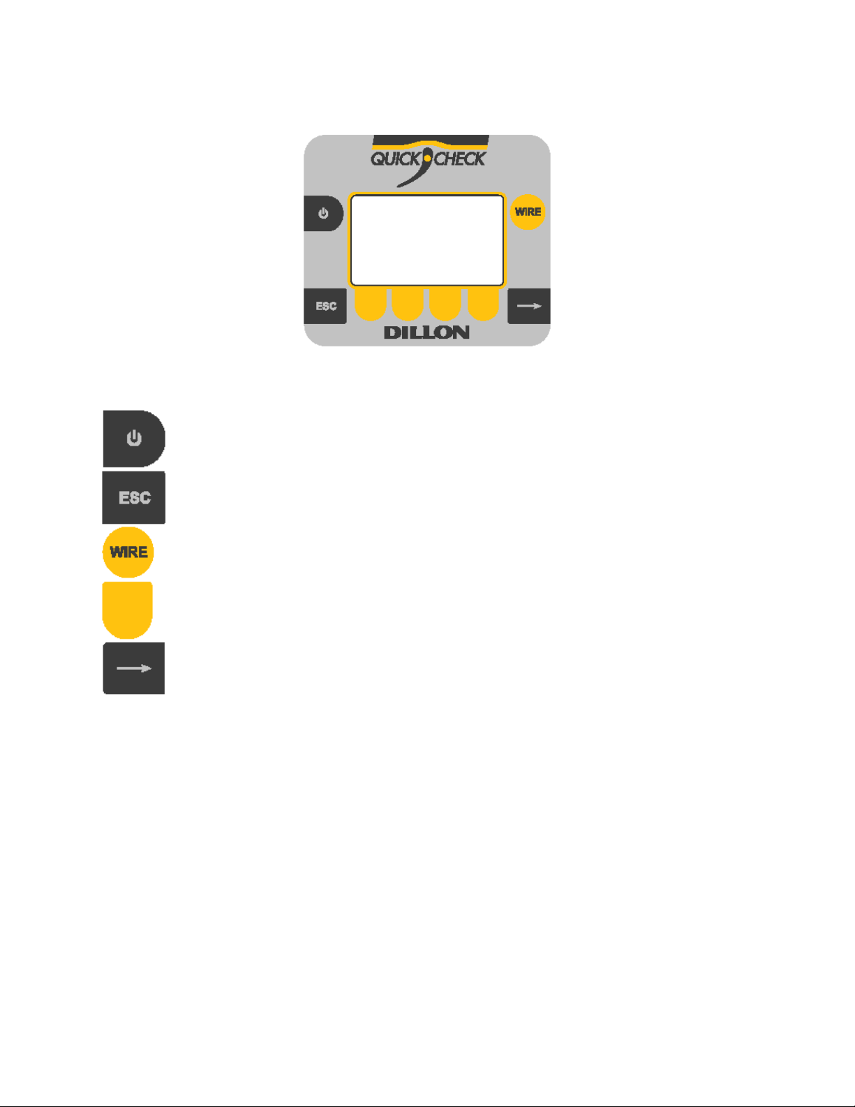
1.2.1 Front Panel and Keys
The front panel of the WTM 502 is shown in Figure 2.
FIGURE 2. WTM 502 FRONT PANEL
Following are descriptions of the keys and their functions:
ON/OFF key. Press this key to power up and turn off the WTM 502.
ESC key. Press this key to escape an area of the menu or to clear the field when in data
entry mode.
WIRE key. Press this key to change the wire diameter you are testing with the WTM 502.
Choose from the listed selection when the desired size is highlighted, press the ENTER
softkey. Up to 15 sizes available.
Soft key. Softkey function changes as needed for different tasks. The soft key labels appear
above the keys themselves. You will use these for operation and configuration
Arrow key. Press this key to reveal more softkeys in a group of softkeys.
1.3 Important features
Quick to use Attaches and removes from tensioned line in seconds. Quick-tensioning
readout for ultra fast line tensioning.
Direct tension readings No more complicated lookup charts! Save time and improve accuracy
Portable & rugged Designed for outdoor use.
Accurate Employs Weigh Bar® technology used for precise weighing.
Multiple wire size storage Stores up to 15 different calibrations.
2.0 OPERATION
Typical operation of the WTM 502 is covered below, followed by explanations of the various display
modes, how to change wire size, how to change the unit of measure, etc.
2.1 Typical Operation
To perform a typical tension measurement, see the Tip below and follow these steps:
1. Turn the unit on by pressing the ON/OFF key…
The display shows DILLON briefly, then, in this example, the screen shows the following:
CF 142 2 V 08/09/05
Page 5
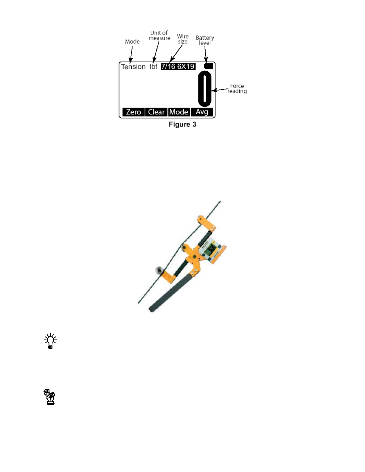
Sample display
2. This example shows the wire is a 7/16”, 6X19 stranded cable and the unit of measure is lbf. Place the
WTM 502 so the two outside sheaves hang on the wire. Insure that the wire rope is riding in the
groove of all three sheaves. See Figure 4. Press the Zero softkey to zero the display
0 should be displayed.
3. Raise the lever arm until it locks in the upright position to apply tension to the wire. Read the line
tension on the display.
4. Release the lever arm and you are ready to perform another measurement.
FIGURE 4. WTM 502 ATTACHED TO CABLE
Take readings at three different places along the cable, moving the tension meter at least four
inches for each reading. Take the average of the readings. The built-in average function is ideal
for this task.
The handle quick release pin should be used when the WTM 502 is attached to a cable that will
be de-tensioned and retensioned. The pin prevents the handle from opening once the tension
falls to a small level. The pin should also be used if the WTM 502 will be installed for a prolonged
period.
Press the WIRE key to list the stored calibrations.
CF 142 3 V 08/09/05
Page 6

2.2 Measurement Practices
Do not apply tension greater than rated capacity of the instrument or overload damage
to the sensor may result.
Do not use the WTM 502 with cable larger than indicated on the sheaves. Overload
and damage to the instrument may result.
Warning
For best measurement, install the WTM 502 at least 2 feet (0.6m) from terminations, clamps or other
hardware. Do not install over the top of wire wrappings.
Take readings at three different places along the cable, moving the tension meter at least four inches for
each reading. Take the average of the readings. The built-in average function is ideal for this task.
Do not use the WTM 502 to measure tension for wires if both of the following are true:
1. No wire calibrations are stored of the same diameter as the wire you are looking to measure, and
2. You do not have sheaves of the same diameter.
If both of these conditions exist, contact Cooper Instruments.
Contact Cooper Instruments to improve accuracy for a specific wire type by calibrating to it.
Insure that the wire rope is riding in the groove of all three sheaves.
Insure sheaves installed agree with sheaves noted in the Wire calibration.
Exception: Sheaves match the wire diameter of the cable to be measured and alternate calibration is
selected as per section 5.2.
The WTM 502 has an internal temperature sensor inside the electronics cavity. Dramatic temperature
changes (such as moving from a warm vehicle to cooler outdoors) requires time for the sensor to reach
the same temperature. Direct sunlight will heat the electronics cavity and cause higher readings than
actual ambient temperature. Ins these cases, use a separate thermometer to determine temperature. Be
certain to enter this temperature into the WTM 502 if using the quick-tensioning mode with the
temperature dependent acceptance window.
For best tension accuracy, use the exact temperature of the wire. This may be widely different from the
ambient temperature if the cable has been sitting in direct sunlight.
Do not mix sheave sizes. This will result in inaccurate measurement and possible
overload.
2.3 Softkey Functions
Now that you’ve seen a simpler operation, we’ll explain the softkey functions. Figure 5 shows the softkeys
available during normal operation.
FIGURE 5. NORMAL MODE SOFTKEYS
CF 142 4 V 08/09/05
Page 7

2.31 Top Level Softkeys
Zero Press this softkey to zero the force display. You would usually press this at the beginning of a
series of tension tests but would not need to do it for every test unless there is some zero
drift.
Clear Press this softkey and you are prompted to clear the Peak reading or the Average. Make your
choice by pressing the appropriate softkey and that value is cleared from memory.
Mode Press the Mode key to scroll through the five display modes. These are explained below:
Live Tension Mode: The display shows the live tension.
Dual Peak Mode: The display shows the live tension on the top display and the peak force
achieved on the bottom display. To clear the peak remove any force on the WTM 502, press
the Clear softkey and follow the prompts.
Average Capture Mode: This mode shows the live tension in the top display and the average
of all captured readings on the bottom display. To capture a reading and add it to the
average, press the Avg softkey when a force is applied to the WTM 502. Follow the prompts
to add (or not) the reading to the average.
Temperature Mode: This mode shows the live tension in the tip display and the current
temperature in the bottom display. Also shown is whether the reading is in Fahrenheit or
Centigrade and if the temp is one that was Entrd (entered) manually.
You can enter the temperature in one of two ways; let the WTM 502 determine the ambient
temperature automatically or key in a temperature manually. Instructions for entering the
temperature are under the Temp softkey description.
Upper and
lower
thresholds
are set in the
Configuration
WIRE menu.
Check-tensioning Mode: Check-tensioning mode permits quick & easy graphical view of the
applied tension versus the desired tension. This mode works well when you are repeatedly
tensioning to the same tension range. This mode displays a bar graph representation of the
tension being applied. See Figure 5. The black bar represents the range of the wire, from
zero to ultimate wire rating. The wide white band is the tolerance window based on upper and
lower thresholds you can enter. The live force is represented by the arrow and the white line
on the black bar. When the force gets within ±5% of the acceptance window, a close-up of
the acceptance window is displayed. See bottom example in Figure 6.
The WTM 502 has automatic tension targeting with temperature. Points may be entered from
a linear Tension-Temperature supplied table for a wire cable. If entered, the check-tensioning
window will automatically float according to the active temperature (manual or automatic).
Use the bottom and top entries from the table. Patent is pending on this feature.
Display when tension is below the dotted, target box.
FIGURE 6. CHECK-TENSION DISPLAY
Display when tension falls within the dotted, target box.
CF 142 5 V 08/09/05
Page 8

To exit the check-tension mode, press any softkey to display the softkey labels, then press
the Mode softkey to scroll to the next mode. The next mode is the first mode that was
described, live tension mode.
Avg Press the Avg softkey to add a displayed tension to the average of other entered readings.
Follow the onscreen prompts.
Press the Right Arrow key to move to the next set of softkeys.
Units Press this key to set the WTM 502 for displaying:
• Force in lbf, kgf or N
• Size of wire in inches or millimeters
• Temperature in Fahrenheit of Centigrade
Temp Press this softkey to choose the source of the temperature reading, the WTM 502 itself
(Meter), outside input (Input) or None. If you choose Input, you are prompted to enter the
temperature. When finished, press the Enter softkey to accept this value.
Next you are prompted to choose Fahrenheit or Centigrade as the temperature unit. When
your choice is highlighted, press the Enter softkey.
An annunciator shows when temperature has been manually entered. See example below:
TEMPERATURE DISPLAY MODE
Setup Press the Setup softkey and you will see these choices; Off, PtFmt, Misc, About, and Test.
These are described below:
Off Press this softkey to enable or disable the auto-shutdown function. If you choose Yes,
you are asked to set a period of time in minutes. Next, press the Enter softkey to accept
this value. You are then asked to set the shutdown type; Fixed, No Load, or No Change.
These are described below;
Fixed – The unit will shutdown after the set number of minutes no matter what happens.
No Load – The unit will shutdown after the set number of minutes only if there is no load on
the unit. This prevents shutdown in the middle of a test.
No Change – The unit will shutdown if there has been no keypad activity or change in
tension after the set number of minutes.
Auto-off can preserve battery life.
PtFmt Not currently used.
Misc Press this softkey to set the following:
Flash – Enables or disables the momentary blinking of the display to acknowledge a key
press.
Zero – Enables the use of the Zero softkey to clear a peak tension value.
Contr – Press this key to adjust the contrast of the LCD display. Press the Up soft key to
lighten the contrast. Press the Down soft key to darken the contrast.
CF 142 6 V 08/09/05
Page 9

There is a keypad shortcut for increasing and decreasing contrast. While in normal display
mode press the Arrow key and the 2nd softkey simultaneously to increase contrast. Press the
Arrow key and first softkey simultaneously to decrease contrast.
Blite – Not currently used.
About Press this softkey to see the following information:
Device – Press this softkey to show a list of information about the WTM 502, such as – serial
number, capacity rating, hardware and software revision levels. Press any key to return to the
previous softkey set.
Calib – Press this softkey to show Calibration Points and the calibration information for the
current wire size. Follow the on-screen prompts.
O. Load – Press this softkey to show an audit count of the number of times the unit has been
overloaded beyond 125% of capacity. Press any key to return to the previous softkey set.
Zero – Press this softkey to show the deadload analysis of the WTM 502. Press any key to
return to the previous softkey set.
Ntwrk – Not used in the WTM 502.
Test Press this softkey and the following softkeys appear:
Batt – Press this softkey to test the battery level.
A-D – Press this softkey to display the A to D counts.
Disp. – Press this softkey to perform a test of the display pixels.
Keys – Press this softkey to test the keypad.
Comm – Not used in the WTM 502.
Ntwrk – Not used in the WTM 502.
Config This is a password protected menu. See section 3.0.
Press the ESC key to return to the normal operating mode. If you made changes to the
configuration of the unit you are prompted to save them or abort the changes. Do so and the unit
returns to normal operation mode.
3.0 CONFIGURATION MODE
3.1 Accessing the Configuration Mode
You need to access the Configuration mode to perform certain tasks. Access to some of these tasks may
be restricted by a supervisor password.
To access Configuration mode:
1. From a normal operating mode, press the Right Arrow softkey
A new softkey set, shown below, appears:
2. Press the Config softkey . . .
The following is displayed:
CF 142 7 V 08/09/05
Page 10

3. Use the Num and Adv keys to enter the Config password. Default is 0. After the number is displayed,
press the Enter key . . .
The following is displayed:
The Num keys increment and decrement the displayed numbers. The Adv key moves the
cursor to the next digit position.
Default Configuration password is 0. If a new password is lost or forgotten, contact Cooper
Instruments.
4. The unit is now in the Configuration mode. To see the rest of the softkeys available in this mode,
press the Right Arrow key. All the Config softkeys are shown below.
The softkeys in the Configuration mode are Wire, Setup, Reso, Comm, Mode, Units, Power, ChPwd,
and Reset. These are described below:
Wire Press this softkey and the wire selection screen is displayed. Choose an existing wire to
change its defining characteristics.
You have the choice of changing the Range, which is sued to set the check-tensioning
function, or the Rating, which is the maximum rating of the cable.
Range – Use this item to set the parameters for the check tensioning display. Follow the
prompts to set the following:
Lower tension limit – This is the lowest acceptable force
Upper tension limit – This is the highest acceptable force
Units – Unit of measure used in defining the tension limit
Rating – Press this softkey and you are prompted to set the ultimate rating for the cable
being used and the unit of measure for tat rating.
Setup Press the Setup softkey to view the Setup softkeys. This is the same as the Setup
softkey described in 2.31 Top Level Softkeys.
CF 142 8 V 08/09/05
Page 11

Reso Press the Reso softkey and you are prompted to enter a display, or count-by, resolution.
Choose from Low, Medium or High.
Low resolution provides the best stability and makes the display easiest to read. High
resolution provides the finest graduations, but sees greater drift from wire creep and nonrepeatability. If the reading is decreasing over time or differing between measurements
on the same line, lowering the resolution will reduce these effects.
Comm Communication output not supported at this time in the WTM 502
Mode Press this softkey to set the display mode on power up. Choices are Last*, Temp,
Check, Avg, Peak, and Force. Use the Sel keys to display your choice and press Enter
to accept it.
Units Press this softkey to set the following:
• Unit of measure on power up. Choices are Last*, C2, C1, N, kgf, and lbf. Use the Sel keys
to display your choice and press Enter to accept it. C2 and C1 are custom units. If you
choose to have custom units, you are prompted to enter the number of pounds in each
custom unit. The WTM 502 will then automatically calculate correct display for the applied
force.
• Enable lbf – Enable of disable the pound-force unit of measure.
• Enable kgf – Enable or disable the kilogram-force unit of measure.
• Enable N – Enable or disable the N unit of measure.
• Enable CUST1 – Enable or disable the Cust1 unit of measure.
• Enable CUST2 – Enable or disable the Cust2 unit of measure.
Custom units of measure are handy when working with multi-part lines.
• Enable C – Enable or disable Centigrade temperature.
• Enable F – Enable or disable Fahrenheit temperature.
Off Press this softkey to enable or disable the auto-shutdown. If you enable this function you
are prompted to set a period of time in minutes. Next, press the Enter softkey to accept
this value. You are then asked to set the shutdown type; Fixed, No Load, or No Change.
These are described below;
Fixed – The unit will shutdown after the set number of minutes no matter what happens.
No Load – The unit will shutdown after the set number of minutes only if there is no load on
the unit. This prevents shutdown in the middle of line tensioning.
No Change – The unit will shutdown if there has been no keypad activity or change in
tension after the set number of minutes.
ChPwd Press this key and you are prompted to enter a new password to access the
configuration menus. Use the softkeys to scroll in a new password and press the Enter
softkey to accept it.
Default Configuration password is 0. If a new password is lost or forgotten, contact Cooper
Instruments.
Reset Press this key and you are asked if you wish to reset the system. Press the Yes softkey
only if you want to continue. Press the No softkey to abort this and return to the previous
screen.
4.0 CHANGING SHEAVES
As you use the WTM 502 on different diameter cables you must change to the correct sheave size. To
change sheaves, remove the hex head screws pointed out in Figure 7 below. Replace the sheaves with
the correct letter sheave and reinsert the screws and tighten.
Insure sheaves installed agree with sheaves noted in the Wire calibration.
CF 142 9 V 08/09/05
Page 12

Exception: Sheaves match the wire diameter of the cable to be measured and alternate calibration is
selected as per section 5.2.
Insure that the wire rope is riding in the groove of all three sheaves.
Do not use the WTM 502 with cable larger than indicated on the sheaves. Overload and damage to the
instrument may result.
Do not mix sheave sizes. This will result in inaccurate measurement and possible overload.
FIGURE 7 CHANGING SHEAVES
5.0 ACHIEVING BEST ACCURACY
5.1 Accuracy
The WTM 502 is an instrument designed to give accuracy that typically exceeds normal requirements for
wire tensioning. You should have an understanding of what factors affect tension measurement accuracy.
5.2 Calibration to Specific Wire Type
While it is best to have the instrument calibrated to the specific wire size(s) and type(s) used, the WTM
502 can often work adequately in other situations. If the best tension accuracy is required, Cooper
recommends that a calibration be performed for that specific wire size and type.
What calibration choice and sheaves should I use?
Situation
Exact wire size and type is
shown in wire list
Wire size is same, but type is
not identical
Wire size is not the same Closest diameter
Wire calibration
selection
Description of exact
match
Description of same wire
diameter
Sheaves noted for that wire size Good
Sheaves matching the wire size
Sheave
selection
Sheaves noted in list Best
being measured
Accuracy
Fair
Contact Cooper Instruments for any additional calibrations you may need.
Do not use the WTM 502 to measure tension for wires if both of the following are true:
CF 142 10 V 08/09/05
Page 13

1. No wire calibrations are stored of the same diameter as the wire you are looking to measure, and
2. You do not have sheaves of the same diameter.
If both of these conditions exist, contact Cooper Instruments.
Contact Cooper Instruments to improve accuracy for a specific wire type by calibrating to it.
5.3 Loading Error
A tensiometer works by deflecting the cable, which makes the cable path longer than when a tensiometer
is not installed. When the tensiometer is removed, the wire tension decreases as the cable length is
restored. This effect is known as loading error. The WTM 502 design elongates the cable by a mere 0.08
inch (2mm), making loading errors extremely small.
5.4 Non-repeatability
The WTM 502’s sheave with bearing design provides the best mechanical performance. It is also superior
at detecting tension that is being added or removed.
5.5 Non-linearity
Most three-point tension meters employ only linear characterization and have large errors at the
midpoints (up to 15%). The WTM 502 uses multi-point segmenting to correct for non-linearity, reducing it
to less than 0.2%.
5.6 Wire Characteristics
Creep Every material including steel exhibits creep under load. It will neck down over time,
quite quickly over the first few seconds and much slower as time progresses. A wire
cable also sees creep from the wire spacing and wind. This effect is seen as a
display that drifts lower after it has been clamped in line.
Variations Material that varies in diameter or shape will have different output at the same
tension
Strands The best cable assembly is one that is perfectly round, as it will not change contact
geometry with the wire twist. The closer the wire cable cross section appears to be
round, the better the measurement performance will be.
6.0 TROUBLESHOOTING
Problem Possible Cause Solution
Powers on momentarily and
turns off
Does not power on
Low battery
Low battery
Batteries installed backwards or no
spring contact
Software reset
Replace with high quality alkaline
batteries
Replace with high quality alkaline
batteries
Insure that positive terminal of
both batteries (nub) face inwardtowards the black cap. Check
that spring is attached to the
battery cap.
Remove battery cap and reinstall
after one minute. Attempt to turn
poser on again
CF 142 11 V 08/09/05
Page 14

Display contrast too light
Display is completely dark Display contrast too dark
Display drifts downward
once installed
Temperature not accurate
Wire material is creeping and internal
friction between wires is relieved
Instrument changed temperature
environments
Instrument exposed to sun Enter temp manually
7.0 SPECIFICATIONS
Hold the Right Arrow key down
while pressing the F2 key several
times to increase the display
contrast. If nothing occurs,
release both keys. Press the
power button and try again.
Hold the Arrow key down while
pressing the F1 key several
times to decrease the display
contrast.
This is normal behavior of wire.
Lower display resolution to mask
this effect.
Allow instrument to remain in
environment until temp stabilizes
or enter temp manually
Power
Display Dot graphic LCD display
Operational keys
Operational
annunciators
Temperature
detection
Display
Resolution
Available options Varied wire sizes
Operating
environment
Dimensions 10” x 23” x 3” (25cm x 59 cm x 8 cm) approximately
Weight 11 lb (5 kg) approximately
2 AA common alkaline batteries. Operational battery life over 40 hours at room
temperature. Battery life is reduced at lower temperatures.
Power, Wire, Escape/Clear,(ESC), Next ( ) and 4 softkeys with changing function
and label, depending on the specific menu in use
Unit of measure, battery level
Temperature accuracy approximately +
2000 lbf/ 1000 kgf / 10,000 N instrument:
Displayed Resolution Setting
Low Med High
lbf (pound-force 10 lbf 5 lbf 2 lbf
kgf (kilogram force) 5 kgf 2 kgf 1 kgf
N (Newton) 50 N 20 N 10 N
Custom units
8000 lbf / 3500 kgf / 35,000 N instrument:
lbf (pound-force 50 lbf 20 lbf 10 lbf
kgf (kilogram force) 20 kgf 10 kgf 5 kgf
N (Newton) 200 N 100 N 50 N
Custom units
For ease of use, the display always counts by a multiple of 1, 2,or 5.
Suitable for outdoor use
Between 101 &
200 divisions
Displayed Resolution Setting
Low Med High
Between 101 &
200 divisions
2° F ( + 1° C)
Between 201 &
500 divisions
Between 201 &
500 divisions
Between 501 & 1000
divisions
Between 501 & 1000
divisions
CF 142 12 V 08/09/05
Page 15

8.0 WARRANTY REPAIR POLICY
Limited Warranty On Products
Any Cooper Instruments product which, under normal operating conditions, proves defective in material
or in workmanship within one year of the date of shipment by Cooper will be repaired or replaced free of
charge provided that a return material authorization is obtained from Cooper and the defective product is
sent, transportation charges prepaid, with notice of the defect, and it is established that the product has
been properly installed, maintained, and operated within the limits of rated and normal usage.
Replacement or repaired product will be shipped F.O.B. from our plant. The terms of this warranty do not
extend to any product or part thereof which, under normal usage, has an inherently shorter useful life than
one year. The replacement warranty detailed here is the buyer’s exclusive remedy, and will satisfy all
obligations of Cooper whether based on contract, negligence, or otherwise. Cooper is not responsible for
any incidental or consequential loss or damage which might result from a failure of any and all other
warranties, express or implied, including implied warranty of merchantability or fitness for particular
purpose. Any unauthorized disassembly or attempt to repair voids this warranty.
Obtaining Service Under Warranty
Advance authorization is required prior to the return to Cooper Instruments. Before returning the item,
contact the Repair Department c/o Cooper Instruments at (540) 349-4746 for a Return Material
Authorization number. Shipment to Cooper shall be at buyer’s expense and repaired or replacement
items will be shipped F.O.B. from our plant in Warrenton, Virginia. Non-verified problems or defects may
be subject to a $100 evaluation charge. Please return the original calibration data with the unit.
Repair Warranty
All repairs of Cooper products are warranted for a period of 90 days from date of shipment. This warranty
applies only to those items that were found defective and repaired; it does not apply to products in which
no defect was found and returned as is or merely recalibrated. It may be possible for out-of-warranty
products to be returned to the exact original specifications or dimensions.
*Technical description of the defect: In order to properly repair a product, it is absolutely necessary for
Cooper to receive information specifying the reason the product is being returned. Specific test data,
written observations on the failure and the specific corrective action you require are needed.
CF 142 13 V 08/09/05
 Loading...