

Page 1

WSC 4329
WIRELESS CELLMITE SYSTEM
USER’S GUIDE
www.cooperinstruments.com
PH: (540) 349-4746 • FAX: (540) 347-4755
Page 2

CONTENTS
1.0 INTRODUCTION ....................................................................................................................1
2.0 M4329/4329M WIRELESS CELLMITE® SYSTEM QUICKSTART........................................1
2.1 M4329M Master CellMite® .................................................................................................................................2
2.2 M4329 Remote Slave CellMite®.........................................................................................................................2
3.0 INSTALLATION AND START UP..........................................................................................4
4.0 RUN MODE ............................................................................................................................4
4.1 Data Measurement .............................................................................................................................................4
4.2 Tare and Reset ...................................................................................................................................................4
4.3 CellMite Setup Options .......................................................................................................................................4
4.3.1 TEDS Tag™/Auto ID....................................................................................................................................4
4.3.2 Temperature Compensation ........................................................................................................................4
4.4 Sensor Setup Options.........................................................................................................................................4
4.4.1 Filtering ........................................................................................................................................................5
4.4.2 Analog Output ..............................................................................................................................................5
5.0 CALIBRATION MODE ...........................................................................................................5
6.0 TECHNICAL INFORMATION/CUSTOMER SUPPORT .........................................................5
7.0 WARRANTY REPAIR POLICY ..............................................................................................5
APPENDIX A – WIRELESS CELLMITE® SPECIFICATIONS.....................................................7
Excitation (M4329) ................................................................................................................................................ 7
Operation (M4329)................................................................................................................................................7
Outputs (M4329) ................................................................................................................................................... 7
Power (M4329/4329M) .........................................................................................................................................7
Mechanical (M4329/4329M) .................................................................................................................................7
Wireless Operation (M4329/4329M)..................................................................................................................... 7
APPENDIX B – M4329/4329M CABLES AND CONNECTORS ..................................................8
APPENDIX C – BRIDGE CONNECTION DIAGRAMS ................................................................9
CF 152 ii Pub. 3775-02
Page 3

1.0 INTRODUCTION
The WSC 4329 and WSC 4329M comprise the Wireless CellMite® System, a versatile precision system of instruments intended for the digital readout of strain gage sensors, such as load cells and extensometers, using wireless
communications between the CellMite® and the host PC. The Wireless CellMite® System can be used with any
member of the CellView family of graphical user interface software including CellView LITE, CellView Multi-
Display, and the CellView Driver, a C-Based API that programmers can use to write their own user interface.
CellMites™ can also be used optionally with an analog digital display that connects directly to the unit and/or the
M4340 CellMite® Battery Pack (ESL p/n 306340).
Here is a quick listing of its features:
• Communications to and from the remote, wireless slave CellMite® (M4329), via the wireless Master CellMite®
(M4329M) connected to the host PC RS232 serial port. The wireless slave CellMite® also allows for direct serial connection to the host PC.
• Remote, wireless slave CellMite® can be powered by the optional M4340 CellMite® Battery Pack (ESL p/n
306340).
• Shunt button can be used to close the shunt relay and take a reading when connected to an analog display.
• Tare button can tare readings when connected to an analog display.
• CellView family of software allows for the measurement load, peak, and valley in various English and metric
units. User-defined units are also supported in the GUI software.
• CellView family of software allows data storage directly to PC that is compatible with Excel spreadsheets
• CellView graphical user interfaces allow the user to Tare readings at any point when data is streaming from
the unit.
• This unit supports the calibration of up to three sensors. Calibration data is stored in the unit. The CellView
family of software allows the user to calibrate various types of strain-gage sensors.
• Calibration for load cells can be done using manufacturer’s milli-volt per volt calibration factor, 2 or 6 point
known mass/extension, or internal precision shunt calibration.
• Two latching solid state relay switches are available to for use through the CellView family of software.
• Automatic identification of calibrated load cells with TEDS Tag.
• Analog output of either a set voltage or a voltage tied to the sensor reading with user defined scale factor and
offset. Wide range, buffered ± 10.00 volt output.
• Other functions available as custom programmed options.
2.0 M4329/4329M WIRELESS CELLMITE® SYSTEM QUICKSTART
This section will help you get your Wireless CellMite® System set up and operating in just a couple of minutes.
The Wireless CellMite® M4329 Hardware provides DC excitation that is suitable for strain gage and resistive
bridges. It is highly recommended that you calibrate sensors and set the system settings while the remote slave
M4329 unit is visible to the user. This can even be done via direct serial connection between the remote slave
M4329 and the host PC. Then the unit can be placed remotely for operation. This is so that the user can see the
status of the remote slave’s LED while setup and calibration are performed.
The typical setup of the system is illustrated below. The remote slave M4329 unit is attached to the load sensors or
extensometers in a remote area (and optionally powered by the M4340 CellMite® Battery Pack) while the M4329M
Master unit is connected by serial cable to the host PC. These two units communicate wirelessly. The commands
sent out by the host PC go to the Master M4329M unit and are sent to the remote slave M4329 unit for processing.
The data received by the M4329 remote unit is sent to the M4329M Master unit, which then sends it into the serial
port of the host PC. The communications have been tested out to a range of 1500 feet.
CF 152 1 Pub. 3775-02
Page 4
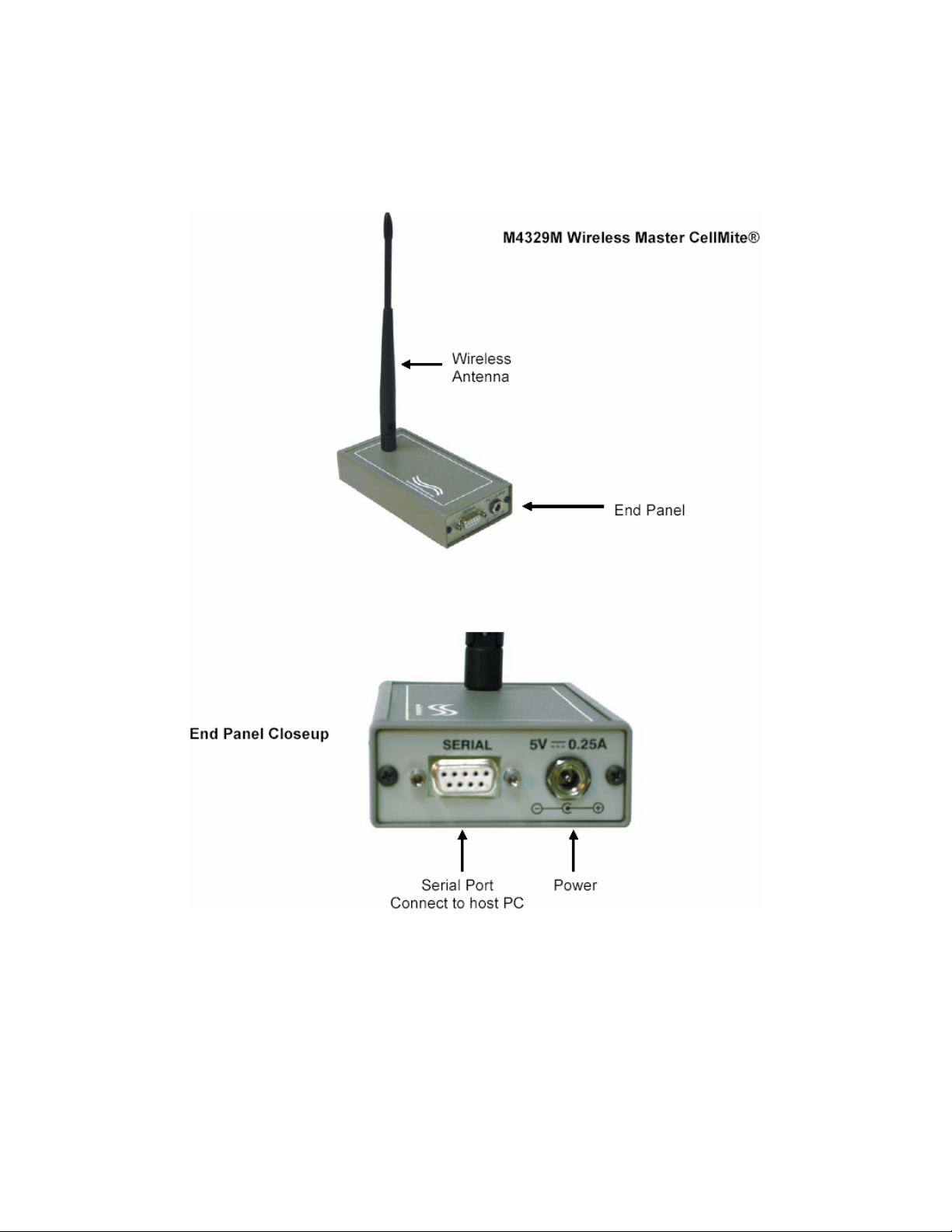
2.1 M4329M Master CellMite®
The M4329M Master CellMite®, in addition to having an antenna, has two connectors on its end panel. One is the
power connector that must be attached to the included 110/240V AC, 60/50 Hz power supply that can then be
plugged into a wall socket. The other connector is a female DB9 serial connector and must be connected to the
host PC via serial cable. The host PC must be running one of the CellView family of software to connect properly
to the M4329M Wireless System.
2.2 M4329 Remote Slave CellMite®
The M4329 Remote Slave CellMite® has two buttons and four connectors available. The connectors are on the
end panels, front and back, and the buttons are on the top panel along with the wireless communications antenna.
• Power – the Power connector must be connected to either a 110/240V AC, 60/50 Hz power supply, or the
M4340 CellMite® Remote Battery Pack (ESL p/n 306340).
• Sensor – DB9 Male connector that connects to the load cell or extensometer taking data readings.
CF 152 2 Pub. 3775-02
Page 5

• Serial – The M4329 can use wireless communications or, optionally, be connected directly to the host PC from
this port by serial cable.
• I/O – Analog Output connector. The M4329 may be programmed to output over this port either a set voltage or
voltage that is tied to sensor readings.
The top panel of the M4329 Remote Slave CellMite®, in addition to having the wireless communications antenna,
has one LED that informs the user of the state of the unit and two buttons, shunt and tare.
• Shunt Button - Pressing on the Shunt Button closes the shunt switch, connecting 60KΩ resistor in the unit in
parallel with the strain gauge. Re-pressing the Shunt Button will open up the shunt switch. The position of the
shunt switch can also be determined by the LED color in run mode. If the shunt switch is closed, the LED will
CF 152 3 Pub. 3775-02
Page 6

be red. Otherwise, it will be green. In calibration mode, the Shunt Button should not be used. If depressed, it
will be ignored.
• Tare Button - Pressing on the Tare Button will tare the sensor reading in run mode. The Tare Button is not
used in calibration. If pressed, it will be ignored.
Once these connections are made, you are set up to use the any of the CellView family of GUI software to add,
calibrate and read data from strain gage extensometers or load sensors.
3.0 INSTALLATION AND START UP
When the Models 4329 and 4329M are powered, the LED on the M4329 remote slave’s top panel will first turn orange, and then green. Green means the unit has finished initialization and is in run mode.
4.0 RUN MODE
The WSC 4329 has two modes of operation, each discernable by looking at the color of the LED on the top of the
unit, Run mode, and System Calibration mode. At power-on it will be in Run mode. The LED is green when the
unit is in Run Mode and blue when the unit is in Calibration Mode.
With the use of one of the family of CellView software, the user can perform various tasks when the unit is in Run
Mode:
4.1 Data Measurement
Measure track, peak and valley from a given, calibrated sensor. The Model 4329 supports load units of Lbs and
Kg, as well as extension units of In, cm, and mm. Either sensor type can also send data as a percentage of a given
base load/extension. The various CellView GUI software packages add to these units and can be customized to
meet user needs. They also have a user-defined unit option that allows the user to create their own unit of measurement by applying a 5
th
order polynomial to the data.
4.2 Tare and Reset
CellView software allows the user to command the unit to tare track data and reset peak and valley measurements.
4.3 CellMite Setup Options
While the CellMite® is in Run Mode, the user can, with the use of CellView software, name the unit with four characters that the unit stores, enable and disable TEDS Tag/Auto ID of sensors, and enable or disable the unit’s internal temperature compensation.
4.3.1 TEDS Tag™/Auto ID
The CellMite® unit is capable of recognizing a sensor that has been calibrated on the unit when that sensor is
plugged into the unit. This is true only if the sensor has been calibrated in one of the three sensor “slots” within the
unit and has not been overwritten with another sensor calibration. This feature is only available in the CellView
LITE software and only valid when a single CellMite® is attached to the system. It cannot work when multiple
CellMites® are attached.
4.3.2 Temperature Compensation
The unit has the ability to compensate for temperature that may affect data readings. By default, temperature
compensation is set ON in the factory unless otherwise requested.
4.4 Sensor Setup Options
Each of the three sensor “slots” within the CellMite® can store calibration data, but they can store sensor-specific
settings in the CellMite® via CellView software. This includes filtering, display decimal points (the unit will use this
to output data to an attached digital display if that option has been purchased), analog output settings if analog output is tied to the sensor output, and the base value to use when track data is in units of %.
CF 152 4 Pub. 3775-02
Page 7

4.4.1 Filtering
The CellMite® can perform moving average filtering of data using up to 128 data points.
4.4.2 Analog Output
The user can set the range of voltage the unit outputs in response to the sensor stimulus. This allows the user to
set any maximum and minimum voltage and offset so that the analog output can be scaled to match the input requirements of nearly any data acquisition system. This includes single ended and bipolar outputs.
5.0 CALIBRATION MODE
The remote slave M4329 unit’s LED turns blue when the unit is placed in calibration mode OR when an address
check is sent to it via the CellView software. If the unit is in calibration mode, the LED will stay blue. If an address
check was sent, as is done by the GUIs to monitor the connection to the unit, the LED will flash blue and return to
green for run mode.
Once in calibration mode, sensors can be calibrated using their manufacturer’s mV/V constant, two or five point
Mass, or precision shunt calibration. The CellView family of software steps the user through the calibration process
for each sensor.
There are three sensor “slots” within the CellMite® unit that can hold these calibrations. Calibration data is maintained in the unit through power cycle.
Once a sensor has been calibrated, the unit must be commanded to stream data to the CellView software. Streaming data, test conditions, and storing of test data are all handled by one or more of the family of CellView software.
Speak to your Cooper Instruments sales representative for more information on CellView software.
6.0 TECHNICAL INFORMATION/CUSTOMER SUPPORT
For technical information or support on any Cooper Instruments product or to order cables and other products that
you may need, please call Cooper Instruments at 800-344-3921.
You can also visit our web site at http://www.cooperinstruments.com
.
7.0 WARRANTY REPAIR POLICY
Limited Warranty on Products
Any Cooper Instruments product which, under normal operating conditions, proves defective in material or in
workmanship within one year of the date of shipment by Cooper will be repaired or replaced free of charge provided that a return material authorization is obtained from Cooper and the defective product is sent, transportation
charges prepaid, with notice of the defect, and it is established that the product has been properly installed, maintained, and operated within the limits of rated and normal usage. Replacement or repaired product will be shipped
F.O.B. from our plant. The terms of this warranty do not extend to any product or part thereof which, under normal
usage, has an inherently shorter useful life than one year. The replacement warranty detailed here is the buyer’s
exclusive remedy, and will satisfy all obligations of Cooper whether based on contract, negligence, or otherwise.
Cooper is not responsible for any incidental or consequential loss or damage which might result from a failure of
any and all other warranties, express or implied, including implied warranty of merchantability or fitness for particular purpose. Any unauthorized disassembly or attempt to repair voids this warranty.
Obtaining Service under Warranty
Advance authorization is required prior to the return to Cooper Instruments. Before returning the item, contact the
Repair Department c/o Cooper Instruments at (540) 349-4746 for a Return Material Authorization number. Shipment to Cooper shall be at buyer’s expense and repaired or replacement items will be shipped F.O.B. from our
plant in Warrenton, Virginia. Non-verified problems or defects may be subject to a $100 evaluation charge. Please
return the original calibration data with the unit.
CF 152 5 Pub. 3775-02
Page 8

Repair Warranty
All repairs of Cooper products are warranted for a period of 90 days from date of shipment. This warranty applies
only to those items that were found defective and repaired; it does not apply to products in which no defect was
found and returned as is or merely recalibrated. It may be possible for out-of-warranty products to be returned to
the exact original specifications or dimensions.
* Technical description of the defect: In order to properly repair a product, it is absolutely necessary for Cooper to
receive information specifying the reason the product is being returned. Specific test data, written observations on
the failure and the specific corrective action you require are needed.
This space intentionally left blank.
CF 152 6 Pub. 3775-02
Page 9

APPENDIX A – WIRELESS CELLMITE® SPECIFICATIONS
Excitation (M4329)
Voltage: 5 VDC
Nom. Load: 350 Ω
Operation (M4329)
Internal Resolution: 24-bit
Input Range: ±5.5 mV/V (Avail. to+200mV/V)
Conversion Rate: 60 per second
Error: 0.01%, ±1 count
Pushbuttons: Tare, Shunt
Precision Shunt: 60 Ω
Indicator: status LED
Outputs (M4329)
Analog: 16-bit, scalable, ±10V
Serial Data: multi-drop RS232
Switches: solid state
Power (M4329/4329M)
5 VDC, 230 mA
(included adapter) 110/240VAC, 60/50 Hz
Compatible with 4 x AA NiMH Rechargable Batteries
Mechanical (M4329/4329M)
Unit Size: 5.5” X 2.75” X1.2”
Unit Weight: 8.9 oz. (252 g)
Wireless Operation (M4329/4329M)
Nominal Frequency: 900 MHz
Classification: Mobile
Complies with Part 15 of the FCC Rules.
CF 152 7 Pub. 3775-02
Page 10

APPENDIX B – M4329/4329M CABLES AND CONNECTORS
The following are the pinouts of the connectors on the M4329/4329M units. The pins that are not listed below are
reserved and should not be connected to external equipment. Serial port pinouts apply to both units. I/O and Sensor pinouts apply only to the M4329 Remote Slave unit.
Serial Port Pins 2,3 and 5 are used for
RS232 communications
Sensor – DB9(M)
Pin # Signal Name
1 Excite - HI
2 Sense - HI
3 Channel “A” Cell Output - HI
4 Channel “A” Cell Output - LO
5 Sense – LO
6 Excite – LO
7 * Auto ID
8 Reserved
9 GND
Serial – DB9(F)
Pin # Signal Name
2 TXD
3 RXD
5 GND
Pins 6-15 Reserved
I/O – 8-Pin Mini-Din( F )
Pin # Signal Name
1-4 Reserved
5 Analog Output
6 GND
Pins 7 & 8 Reserved
Note: Items preceded by
an asterisk are optional.
CF 152 8 Pub. 3775-02
Page 11

APPENDIX C – BRIDGE CONNECTION DIAGRAMS
External
Excite HI
Sense HI
R1
R2
Strain
Gauge
R3
Shunt Switch
60KΩ shunt
Cell Output HI
Sense LO
Excite LO
Cell Output LO
Quarter Bridge Connection Diagram.
Three external resistors should be added as recommended by the
sensor manufacturer to complete the bridge circuit.
CF 152 9 Pub. 3775-02
Page 12

Excite HI
Sense HI
External
Shunt Switch
R1
60KΩ shunt
Cell Output HI
R2
Sense LO
Excite LO
Cell Output LO
Half Bridge Connection Diagram.
Two external resistors should be added as recommended by the sen-
sor manufacturer to complete the bridge circuit.
CF 152 10 Pub. 3775-02
Page 13

Excite HI
Sense HI
Shunt Switch
60KΩ shunt
Cell Output HI
Sense LO
Excite LO
Cell Output LO
Full Bridge Connection Diagram.
Complete circuit provided by the sensor manufacturer. No external resistors are required.
CF 152 11 Pub. 3775-02
 Loading...