

Page 1

WFC 900
WELD FORCE PROBE
USER’S GUIDE
www.cooperinstruments.com
PH: 540-349-4746 FAX: 540-347-4755
Page 2
TABLE OF CONTENTS
1.0 INTRODUCTION ...................................................................................................................1
1.1 Overview.......................................................................................................................................... 1
1.2 Quick Operation Guide................................................................................................................... 1
1.3 Instrument Layout .......................................................................................................................... 1
1.3.1 LCD Display.............................................................................................................................. 1
1.3.2 Low Battery Indicator .............................................................................................................. 1
1.3.3 Decimal Point Position ............................................................................................................ 2
1.3.4 Incremental Display Step ........................................................................................................ 2
1.3.5 Load Cell................................................................................................................................... 2
1.4 Maximum Safe Overload ................................................................................................................ 2
1.5 Front and Side Views ..................................................................................................................... 2
1.6 Dimensions ..................................................................................................................................... 3
1.7 Specifications ................................................................................................................................. 3
2.0 OPERATION ..........................................................................................................................4
2.1 Battery Replacement...................................................................................................................... 4
2.2 Turning the Instrument On and Off............................................................................................... 4
2.3 Zeroing the Display ........................................................................................................................ 4
2.4 Restoring the Calibrated Zero ....................................................................................................... 4
2.5 Reading the High/Low Values ....................................................................................................... 5
2.6 Clearing the High/Low Values ....................................................................................................... 5
3.0 FIELD SELECTABLE FEATURES ........................................................................................5
3.1 Introduction..................................................................................................................................... 5
3.2 Setup Menu Operation ................................................................................................................... 5
3.3 Enable Options (“ ”) Description ............................................................................................... 6
3.3.1 Auto-off Feature ....................................................................................................................... 6
3.3.2 Always-On Feature .................................................................................................................. 6
3.3.3 [Zero] Button Disable Feature ................................................................................................ 7
3.3.4 [Hi/Lo] Button Disable Feature ............................................................................................... 7
3.3.5 [Clear] Button Disable Feature ............................................................................................... 7
3.4 Enable Options (“ ”) Menu Item ................................................................................................. 7
3.5 Engineering Units (“ ”) Menu Item ......................................................................................... 7
3.6 Auto-off time (“ “) Menu Item.................................................................................................. 8
3.7 Update Rate (“ ”) Menu Item .................................................................................................. 8
3.8 Internal Software Version (“ ”) Menu Item .............................................................................. 8
4.0 CALIBRATION.......................................................................................................................9
4.1 Calibration Considerations............................................................................................................ 9
4.2 Required Forces ............................................................................................................................. 9
4.3 Calibration Procedure .................................................................................................................... 9
4.3.1 Enter Forces to be Applied ..................................................................................................... 9
4.3.2 Apply Forces .......................................................................................................................... 11
4.4 Rear View of Front Face Panel .................................................................................................... 12
4.5 Calibration Error Messages ......................................................................................................... 12
5.0 TROUBLESHOOTING .........................................................................................................12
5.1 Introduction................................................................................................................................... 12
5.2 Help Message Codes.................................................................................................................... 13
5.3 Troubleshooting Hints ................................................................................................................. 13
WARRANTY REPAIR POLICY..................................................................................................13
WFC 900 ii Rev. D: 3/03
Page 3

Limited Warranty On Products.......................................................................................................... 13
Obtaining Service Under Warranty ................................................................................................... 14
Repair Warranty.................................................................................................................................. 14
WFC 900 iii Rev. D: 3/03
Page 4
1.0 INTRODUCTION
1.1 Overview
The WFC 900 is a rugged, hand-held instrument for accurately calibrating weld electrode force on resistance
welding machines. This device helps ensure compliance with ISO 9000 or QS 9000 quality requirements by taking
the guesswork out of setup. Measuring accurate force levels at the electrode tips helps eliminate inaccuracies of
the line-pressure readings, air cylinder friction, and mechanical wear.
The WFC 900 is designed for long life in the harsh welding environment by using Cooper’s standard fully-welded
load cell construction and NEMA 4 electronics packaging. The easy-to-use design includes a simple push-button
format and a large LCD display that provides both continuous and peak (maximum) force values in keypadselectable engineering units.
High-speed digital electronics sample readings during the squeeze-weld-hold sequence and capture the peak force
for display. A simple, one-button CLEAR prepares the instrument for the next reading. Two standard 9-volt alkaline
batteries provide 80 hours of continuous use. Battery life is maximized with a programmable power-off feature.
1.2 Quick Operation Guide
1. Depress the [On/Off] button to power up the instrument. Wait about 5 seconds for the instrument to warm up.
2. If a non-zero value appears on the display, press and hold the [Zero] button until the display reads “
takes about three seconds).
3. Insert probe, initiate welder, and take reading.
4. Press and hold the [Hi/Lo] button until the display reads “
5. Press [Clear] to clear the maximum value in preparation for the next reading.
6. As shipped from the factory, the instrument will automatically shut itself off if no buttons have been pressed in
four minutes.
Note: The WFC 900 is a force calibration device designed to measure the force between electrodes on resistance
welders. It can withstand passing current through the force transducer.
It is recommended for the safety of the operator and the WFC 900 to disable current before
operation. Many repeated current firings may damage the weld force indicator.
” to read the maximum (or peak) force value.
” (this
1.3 Instrument Layout
1.3.1 LCD Display
The 4½-digit liquid crystal display (LCD) readout displays the load applied to the instrument, interacts with the user
when the instrument is being set up or calibrated, and indicates if there is a problem with the instrument.
When a WFC 900 instrument is turned on, it illuminates all LCD segments. Then, the engineering units the gauge
will be using appears on the display. Most WFC 900 instruments are calibrated in pounds (“
instrument has conversion factors for many standard engineering units built in. However, if the instrument displays
(special) it has been specially calibrated to another engineering unit at the factory. In that case, the serial
number tag on the top of the instrument will indicate the engineering units being used and the capability to select
other engineering units should not be used.
After the display of the engineering units, the force applied to the load cell is shown on the display. If the load
applied to the load cell is above the instrument's ability to measure, the display will indicate this overrange condition
by showing a "
" on the far left hand side of the display. The display will read " " if the instrument is underranged.
”) and the
1.3.2 Low Battery Indicator
On the left side of the display, just above the minus sign, is the low battery indicator (in the shape of an arrow).
When the battery voltage is less than 5 volts, the display will be blanked and the low battery indicator will illuminate
to indicate that the batteries should be replaced. The low battery indicator can be seen when the instrument is
turned on and all segments of the display are momentarily lighted.
WFC 900 1 Rev. D: 3/03
Page 5
When the low battery indicator is illuminated, change the batteries as soon as possible. The instrument will not
function if the battery voltage falls below approximately 4 volts.
1.3.3 Decimal Point Position
The decimal point position automatically changes depending upon:
• the user selected engineering units
• the load range of the instrument.
The decimal point position cannot be changed manually.
1.3.4 Incremental Display Step
The incremental display step is the value by which the last digit of the display will change. This value will be 1, 2, or
5 display counts. It automatically changes depending upon:
• the user selected engineering units
• the load range of the instrument
The incremental display step cannot be changed manually.
1.3.5 Load Cell
The WFC 900 instrument can be ordered with one of two types of load cells: those with a load sensing button, and
those with a load sensing indentation. The load sensing button is useful when the unit is used with projection
welders. The load sensing indentation is useful for most spot welding applications.
1.4 Maximum Safe Overload
Maximum safe overload is the force that the instrument can experience occasionally without loss of accuracy or
permanent damage.
Force Range (lbs.)
0 - 500 = 500 750
0 - 1000 = 1K 1500
0 - 2000 = 2K 3000
0 - 5000 = 5K 7500
0 - 10000 = 10K 15000
Table 1: Maximum Safe Overload
Maximum Safe Overload
(lbs.)
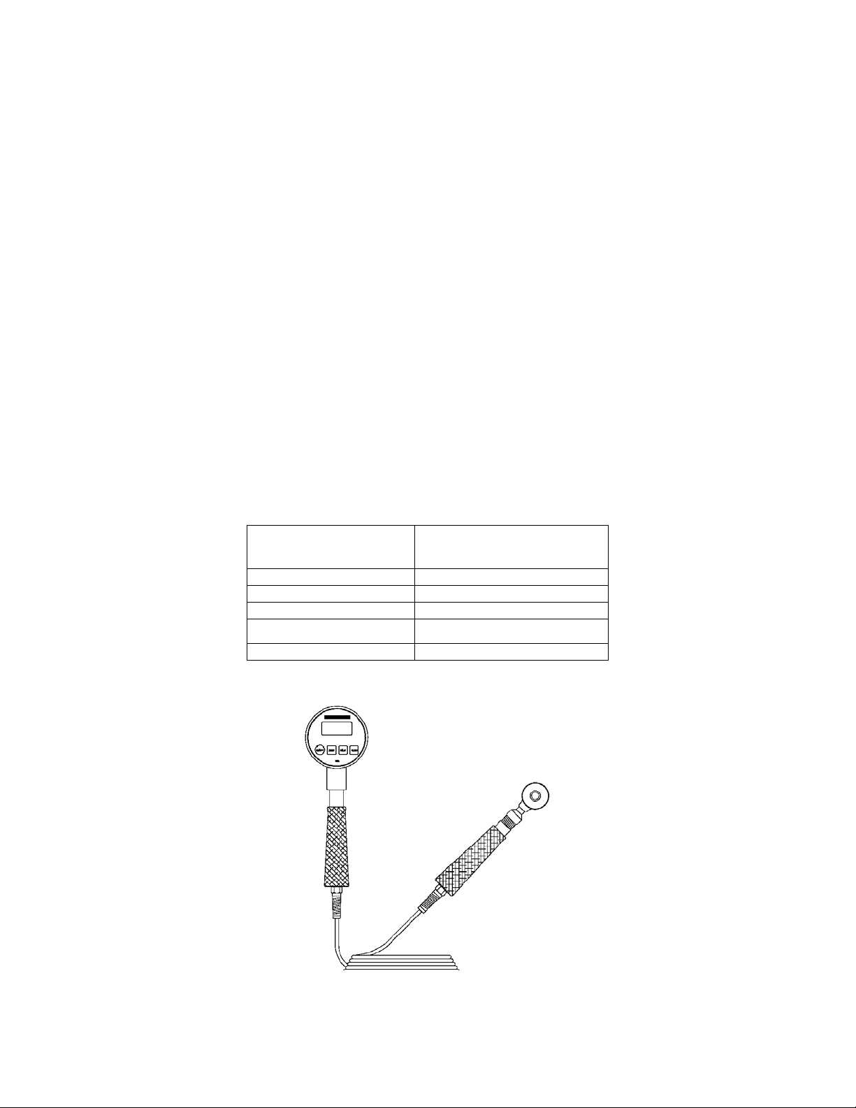
1.5 Front and Side Views
Figure 1-1. Model WFC 900 Front View (2-handed version)
WFC 900 2 Rev. D: 3/03
Page 6
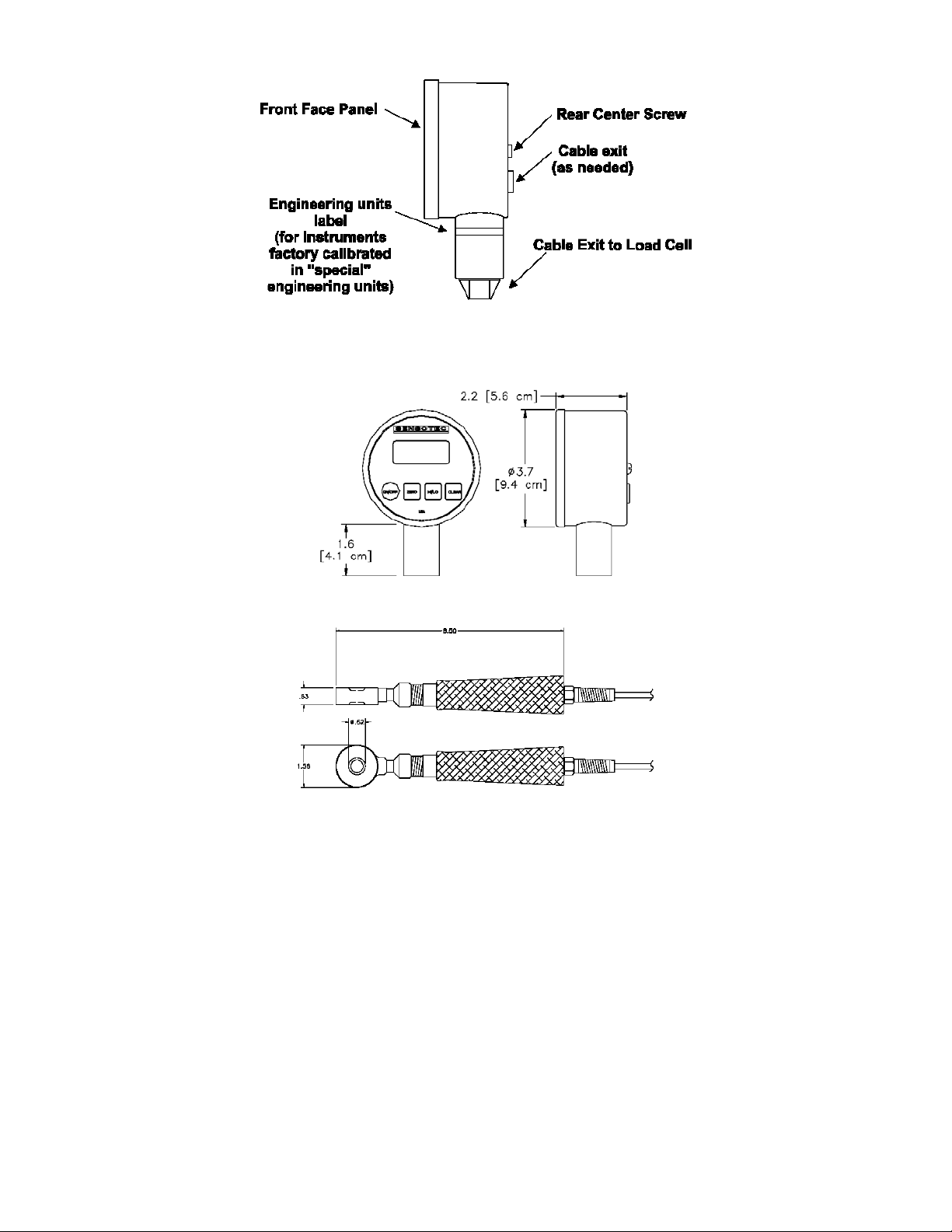
Figure 1-2. Model WFC 900 Display Side View
1.6 Dimensions
Figure 1-4. Model WFC 900 Load Cell Dimensions (2000 lbs. Range with Sensing Indentation)
1.7 Specifications
Figure 1-3. Model WFC 900 Display Dimensions
Cooper continually improves its products, and thus these specifications are subject to change without notice.
Display Diameter: 3.7 inches
Accuracy: 0.5%
Operating Temperature: 30 to 180 ºF
Force Ranges 0 to: 1000, 2000, 5000, 10000 lbs.
Overload Capability: 150% of full-scale range
Calibration Engineering Units: lbs
Built-in Engineering Unit Conversion: lbs, Kg, kN, N, g (field selectable)
Sampling Rate: 19.2kHz internal; 24Hz display update
Power Requirements: two 9 Volt alkaline batteries provide approximately 80 hrs continuous life
Load Cell Material: BeCu
Housing Material: Stainless steel
High and Low Capture: Standard, same update rate as display
Zero and Span Adjustment: Standard
WFC 900 3 Rev. D: 3/03
Page 7

Front Panel Membrane Tactile feedback, raised buttons
Calibration Data: Stored on non-volatile memory chip
Package: All-welded load cell; NEMA 4 rated display unit
Weld Current: Survives accidental current discharge
2.0 OPERATION
2.1 Battery Replacement
Two nine-volt alkaline batteries (NEDA 1604) are recommended for use in the Model WFC 900. This is a common
type of battery that is available at many stores. With two alkaline batteries, a Model WFC 900 instrument will
operate continuously on for approximately 80 hours. Carbon-zinc batteries (sometimes labeled as “general
purpose” or “heavy duty”) should not be used. Please note that the temperature specifications of the batteries you
purchase may not be the same as those of the Model WFC 900.
If two batteries are not available, the instrument will operate with only one alkaline battery installed in either clip.
However, this will reduce the continuous operation time to approximately 40 hours. The use of two lithium batteries
will allow your Model WFC 900 instrument to operate continuously for over 160 hours.
To install the batteries:
1) Remove the center screw on the back of the instrument.
2) Remove the front face panel from the case.
3) The colored ribbon cable extending from the sensor to the electronics may be disconnected to make the battery
installation more convenient.
4) Replace the batteries one at a time, making sure of the correct polarity.
5) Reconnect the sensor cable to the electronics.
ÎImportant note: The correct orientation of the sensor cable is shown in Section 4.4. If you connect the sensor
cable backwards, the instrument will not operate correctly.
6) Replace the front face panel.
7) Carefully replace the rear center screw.
Note: Calibration and setup values are stored in a nonvolatile memory, and are not lost during battery replacement.
2.2 Turning the Instrument On and Off
Push the [On/Off] button to turn the instrument on or off.
As the instrument turns on, every segment on the display is momentarily lighted. The high/low data values are
cleared.
2.3 Zeroing the Display
Hold the [Zero] button until the display shows “
The instrument will retain this zero value even after the instrument has been turned off.
” (about 5 seconds).
2.4 Restoring the Calibrated Zero
To restore the zero, first press and hold the [Clear] button, while holding
[Clear]...
... press the [Zero] button. Hold both buttons until the display shows “ ”,
then release.
The "calibrated zero" is the zero value of the instrument at the time it was last calibrated. Restoring the calibrated
zero can be used to “undo” an inadvertent press of the [Zero] button.
WFC 900 4 Rev. D: 3/03
Page 8

2.5 Reading the High/Low Values
The high and low values are updated at the same rate as the tracking value.
Press the [Hi/Lo] button once to read the highest value since the last time the
data was cleared.
The word “
instrument is not displaying the "live" tracking value of the applied force. However, the instrument is still monitoring
the applied force and updating the high and low values.
The word
instrument is not displaying the "live" tracking value of the applied force. However, the instrument is still monitoring
the applied force and updating the high and low values.
” and the corresponding value will flash intermittently on the display. This flashing indicates that the
and the corresponding value will flash intermittently on the display. This flashing indicates that the
Press the [Hi/Lo] button a second time to read the lowest value since the last
time the data was cleared.
Press the [Hi/Lo] button a third time to return to the “live” tracking mode. The
display will show “---“ to indicate that the instrument has returned to the “live”
tracking mode.
2.6 Clearing the High/Low Values
Press the [Clear] button to erase the high and low data values.
The high and low data values are also cleared when the instrument is turned off.
3.0 FIELD SELECTABLE FEATURES
3.1 Introduction
This Chapter discusses the field selectable features available on the model WFC 900 Force Gage. These features
can be activated, deactivated and modified via the Setup Menu accessed by the front panel. These field selectable
features include:
• enabling the automatic power off feature to conserve battery life
• disabling the front panel buttons
• changing the engineering units used to display the applied force.
• adjusting the automatic power off time
• changing the update rate
3.2 Setup Menu Operation
All of the field selectable features are accessed via the Setup Menu. This section discusses its operation. To
change a feature with the Setup Menu:
Make sure the instrument is turned off. Then, press the [On/Off] button.
While unit is checking the display (lighting all LCD segments simultaneously),
press and hold down the [Zero] button.
The display now reads “
”, which is the first item of the Setup Menu. Release the [Zero] button.
Pressing and releasing the [Zero] button will scroll down through the available
Setup Menu items.
WFC 900 5 Rev. D: 3/03
Page 9

The table below provides a list of the items available in the Setup Menu and a brief description of each.
Table 2: Setup Menu Items
Display Menu Item Purpose
Low Limit setpoint N/A
High Limit setpoint N/A
Enable Options Enable Auto-Off feature;
Engineering units Change engineering units used to display
Auto-off time Change Auto-Off power down time
Update rate Change update rate of force readings
Internal software
revision
Disable front panel buttons
force
Display internal software part number and
revision
When the menu item you wish to change is displayed, press [Clear].
The display now shows the present setting of that menu item. If you only wish to examine the present setting of the
menu item, you can use the [On/Off] button to turn the instrument off. Otherwise...
Use the [Hi/Lo] and [Clear] buttons to scroll up and down, respectively.
If you wish to abandon the changes you made to this setting, you can use the [On/Off] button to turn the instrument
off. Otherwise...
The next menu item will be displayed after the instrument stores the setting into memory.
Once the setting you want is displayed, press the [Zero] button to store this
setting into memory.
3.3 Enable Options (“ ”) Description
The Enable Options (“ “) menu item controls the features described in the sub-sections below.
3.3.1 Auto-off Feature
The unit will shut itself off if no buttons are pressed for the time duration specified with the Auto-off time (“ “)
menu item. The unit can also be shut off with the [On/Off] button. This feature is useful for conserving battery life.
The instrument is shipped with this feature enabled.
3.3.2 Always-On Feature
The [On/Off] button is disabled and will not shut the unit off. This mode is used so that the high and low capture
values, output signals, or limit alarms are not interrupted if an operator tries to shut the unit off during testing or
monitoring.
WFC 900 6 Rev. D: 3/03
Page 10

3.3.3 [Zero] Button Disable Feature
This feature disables the ability to zero the display of the instrument. The ability to restore the calibrated zero is also
disabled. When the [Zero] button is pressed, the display momentarily reads “ ” which indicates that the button
has been disabled via the Enable Options menu item.
3.3.4 [Hi/Lo] Button Disable Feature
This feature disables the ability to read the stored high and low values on the display. The display will always read
the “live” tracking value of the applied force. When the [Hi/Lo] button is pressed, the display will momentarily read
” which indicates that the button has been disabled via the Enable Options menu item.
“
3.3.5 [Clear] Button Disable Feature
This feature disables the ability to clear the high and low data values with the [Clear] button. The ability to restore
the calibrated zero is also disabled. When the [Clear] button is pressed, the display momentarily reads “ ” which
indicates that the button has been disabled via the Enable Options menu item. NOTE: The high and low data
values may also be cleared by turning the unit off and back on, unless the Always-on feature is used.
3.4 Enable Options (“
To activate or deactivate the features described in the previous section, the setting of the Enable Options (“ “)
menu item must be changed. The procedure to change the setting of a menu item is described in the “Setup Menu
Operation” section earlier in this Chapter. The setting value of the Enable Options (“ “) menu item is obtained by
adding together the values of the desired options according to the table below.
”) Menu Item
Table 3: Enable Options (“ “) settings
Feature Disabled Enabled
Auto-off 0 1
Always-on 0 2
[Zero] button 4 0
[Clear] button 16 0
[Hi/Lo] button 32 0
For example, to enable the Auto-off feature and disable the [Zero] button enter a setting value of “0005”. As another
example, to disable both the [Zero] and the [Clear] buttons enter a setting value of “0020”. If the Auto-off and
Always-on features are both activated, the unit will behave as follows: The [On/Off] button can turn the instrument
on but it cannot turn the instrument off. The only way to turn the instrument off is not to press any buttons for the
duration specified in the Auto-off time (“ “) menu item. Note that the Auto-off time (“ “) setting can be
several hours.
3.5 Engineering Units (“ ”) Menu Item
The Engineering Units (“ “) menu item determines which units-of-measure are used to display the force
readings. Most WFC 900 instruments are calibrated in lbs. and the instrument has conversion factors for many
WFC 900 7 Rev. D: 3/03
Page 11

standard engineering units built in. The procedure to change the setting of a menu item is described in the “Setup
Menu Operation” section earlier in this Chapter.
Note: If the instrument displays “ ” (special) when powering up, it has been specially calibrated to another
engineering unit. The ability to change the engineering units is not available. The table below gives a list of the
engineering units built into the instrument.
Table 4: Engineering Units (“ ”) Available Settings
Setting Engineering Unit / Comment
for factory use only
lbs
N
KN
g
kg
3.6 Auto-off time (“ “) Menu Item
The Auto-off time (“ “) menu item is only meaningful if the Auto-off feature is enabled in the Enable Options
(“ “) menu item. The procedure to change the setting of a menu item is described in the “Setup Menu Operation”
section earlier in this Chapter. The table below gives a list of the available settings for the Auto-off time (“
“).
Table 5: Auto-off time (“ “) Available Settings
Setting Time
0 4 minutes
1 1 hour
2 2 hours
3 3 hours
4 4hours
5 5 hours
6 6 hours
7 7 hours
8 8 hours
3.7 Update Rate (“ ”) Menu Item
The Update Rate (“ ”) menu item determines the number of times the force readings are updated per second.
The track, high and low values are all updated at this rate. The update rate can be varied from 5 to 24 updates per
second. As shipped from the factory, the update rate is set to 24 per second.
Important Note: To receive maximum accuracy in resistance welding applications, it is important to leave the
update rate set at 24 per second.
3.8 Internal Software Version (“ ”) Menu Item
The Internal Software Version (“ ”) menu item displays the part number and version number of instrument’s
operating software. The software part number and version number are of the form:
084-1087-02 1.19
Where the “084-1087-02” is the part number, and the “1.19” is the version number. Since this string is too long to fit
on the 4½ digit-display, pressing either the [Hi/Lo] or [Clear] buttons will scroll through this string 4 characters at a
time.
WFC 900 8 Rev. D: 3/03
Page 12

4.0 CALIBRATION
4.1 Calibration Considerations
In order to obtain optimum performance from the model WFC 900 instrument when testing or re-calibrating, Cooper
recommends the following:
• Allow a 5-minute warm-up period before testing or calibration.
• The force standard you use should be at least 4 times more accurate than the specification of the WFC 900
instrument.
4.2 Required Forces
In order to re-calibrate the instrument, you must have a precision force standard that can produce the zero-scale,
half-scale and full-scale forces for the instrument's range. For example, if your WFC 900 instrument has a range of
500 lbs, your force standard must be able to accurately produce forces of 0 lbs, 250 lbs, and 500 lbs.
If your force standard cannot produce these exact values, the instrument can be programmed in the field to expect
slightly different values during the re-calibration process. For example, if your calibrated weights are equal to 0 lbs,
251 lbs and 498 lbs, you can program the instrument to expect these weights during the re-calibration process.
All WFC 900 instruments are calibrated in lbs regardless of the field-selected engineering units. However, if the
instrument displays the word “ ” (special) when it powers up, it has been specially calibrated to another
engineering unit. In that case, the serial number tag on the top of the instrument will indicate the engineering units
that will be used for re-calibration.
To maintain NIST traceability, Cooper can re-calibrate a WFC 900 instrument for you. NIST certificates may be
ordered as a separate accessory for a nominal fee.
Table 6: Required Forces (all in lbs)
Force Range
500 0 250 500
1K 0 500 1000
2K 0 1000 2000
5K 0 2500 5000
10K 0 5000 10000
4.3 Calibration Procedure
Calibration Point 0
(zero-scale force)
Calibration Point 1
(half-scale force)
Calibration Point
2 (full-scale force)
The calibration procedure consists of two parts, the first of which may not be necessary in all applications.
• First, the instrument is told exactly what zero-scale, half-scale and full-scale forces are to be applied during the
calibration procedure.
• Second, the forces are applied to the instrument.
The following two sections explain this procedure.
4.3.1 Enter Forces to be Applied
The expected force values to be applied during calibration are accessed via the Factory Configuration Menu. This
section discusses its operation.
To change a value with the Factory Configuration Menu:
Make certain the instrument is turned off.
WFC 900 9 Rev. D: 3/03
Page 13

Open up the instrument by removing the center screw on the back. Next, remove the front face panel. Take care
not to break the wires extending from the sensor to the electronics. As indicated on Figure 4-1, move the mode
jumper from the "park" position to the "configure" position.
Hold the [On/Off] button, then press the [Hi/Lo] button. The display will
momentarily read “
”.
Release the [Hi/Lo] button, and the display will read “
” which is the first item of the Factory Configuration
Menu.
Pressing and releasing the [Zero] button will scroll down through the available
Factory Configuration Menu items.
The table below provides a list of the items available in the Factory Configuration Menu and a brief description of
each.
Table 7: Factory Configuration Menu Items
Display Menu Item Purpose
Decimal Point How many decimal points are used
to edit the , and
Factory Configuration Menu items.
Zero-Scale Point The expected value in lbs of the
force to be applied at zero scale.
Half-Scale Point The expected value in lbs of the
force to be applied at half scale.
Full-Scale Point The expected value in lbs of the
force to be applied at full scale.
Input Range For factory use only. Do not
change this setting.
When the menu item you wish to change is displayed, press [Clear].
The display now shows the present setting of that menu item. If you only wish to examine the present setting of the
menu item, you can use the [On/Off] button to turn the instrument off. Otherwise...
Use the [Hi/Lo] and [Clear] buttons to scroll up and down, respectively.
If you wish to abandon the changes you made to this setting, you can use the [On/Off] button to turn the instrument
off. Otherwise...
Once the setting you want is displayed, press the [Zero] button to store this
setting into memory.
The next menu item will be displayed after the instrument stores the setting into memory.
WFC 900 10 Rev. D: 3/03
Page 14

After you have finished using the Factory Configuration Menu, the mode jumper must be moved from its
"configure" position to its "park" position as indicated in Figure 4-1. Close the unit up and replace the center
screw.
4.3.2 Apply Forces
Make certain the instrument is turned off.
Open up the instrument by removing the center screw on the back. Next, remove the front face panel. Take care
not to break the wires extending from the sensor to the electronics. As indicated on Figure 4-1, move the mode
jumper from the "park" position to the "calibration" position.
The display will begin to alternately flash between the force required for calibration point #0 (for example “
and “----“). If you wish to abandon the calibration procedure, press the [On/Off] button to turn the unit off.
Otherwise...
Next, the display will begin to alternately flash between the force required for calibration point #1 (for example,
“
”) and “----“.
Hold the [On/Off] button, then press the [Clear] button. The display will
momentarily read “
Apply the indicated force to the instrument. Press [Clear] until “ ” is
displayed, indicating that the reading is being stored.
”.
”
Apply the indicated force to the instrument. Press [Clear] until “
displayed, indicating that the reading is being stored.
Finally, the display will begin to alternately flash between the force required for calibration point #2 (for example,
” and “----“).
“
When the last force point has been entered, the instrument will turn itself off. At this time, the mode jumper must be
moved from its "calibration" position to its "park" position as indicated in Figure 4-1. Close the unit up and replace
the center screw.
Check that the instrument has been calibrated properly by turning it back on and using the force standard.
Apply the indicated force to the instrument. Press [Clear] until “
displayed, indicating that the reading is being stored.
” is
” is
WFC 900 11 Rev. D: 3/03
Page 15

4.4 Rear View of Front Face Panel
Figure 4-1. Front face panel (rear view), showing mode jumper positions
and orientation of sensor cable
4.5 Calibration Error Messages
If unexpected forces are encountered during the calibration procedure, the WFC 900 instrument will alert the user
by flashing the word “
cannot continue, and that you must turn the instrument off and recalibrate again when the error has been corrected.
A list of error message numbers and their causes is given in “TROUBLESHOOTING” in Chapter 5.
” and a message number on the display. This indicates that the calibration process
5.0 TROUBLESHOOTING
5.1 Introduction
This chapter provides information on correcting common problems that may be encountered operating and
calibrating the instrument.
WFC 900 12 Rev. D: 3/03
Page 16

5.2 Help Message Codes
If the instrument detects a problem during its power-on self-test, operation, or calibration, it will alert the user by
flashing the word “ ” and an error message code number on the display. The instrument cannot continue
operation and you must turn the instrument off and correct the error.
• “ ”: Calibration error.
Analog to digital converter overrange.
One of the force points is above the calibration range of the instrument. Or, the sensor cable is not connected
properly.
• “
Analog to digital converter underrange.
One of the force points is below the calibration range of the instrument. Or, the sensor cable is not connected
properly.
• “
The applied forces at any two calibration points did not differ enough.
• “
The engineering unit conversion that you selected cannot be rendered on a 4½-digit display. For
consider the case of an instrument with a range of 2000 lbs. If you were to select grams (“ ”) in the
Engineering Units (“ ”) menu item the instrument would signal this error. This is because 2000 lbs equals
907184 grams, which cannot be shown on a 4½-digit display.
• “
“ ”: Non-volatile memory read error.
“
“ ”: Non-volatile memory version mismatch.
“ ”: Analog-to-digital converter not ready.
Turn the instrument off and on again. If these problems persist, contact Cooper.
”: Calibration error.
”: Calibration error.
”: Self-test error.
example,
”: Non-volatile memory write error.
”: Non-volatile memory verify error.
5.3 Troubleshooting Hints
• Verify that the power source is operating correctly. Make sure the batteries are fresh or that the external supply
is wired correctly.
• Verify that you have set the instrument to read in the desired units-of-measure.
• Verify that the sensor cable is connected correctly. The figure on page 31 shows the correct orientation of the
sensor cable.
• If you have changed the display update rate from the factory default of 24 per second, it may now be set too
low for your application and this may be interpreted as the peak readings being too low. Try increasing the
display update rate.
• The sensor and the electronics are a matched set. Do not, under any circumstances, exchange sensor and
electronics on two different instruments.
• The [Zero] button must be held down for 5 seconds before the display will be zeroed. This is in order to prevent
unintentional zeroing of the display.
• As shipped from the factory, the instrument will shut itself off after four minutes unless any button is pressed.
You can adjust this Auto-off feature if you wish.
• Inspect the instrument for physical damage. If the instrument is physically damaged, consult the factory for
repair. Do not attempt repairs as this may void the warranty.
• When all else fails, disconnect the batteries for 5 seconds, then reinstall.
WARRANTY REPAIR POLICY
Limited Warranty On Products
Any Cooper Instruments product which, under normal operating conditions, proves defective in material or in
workmanship within one year of the date of shipment by Cooper will be repaired or replaced free of charge provided
that a return material authorization is obtained from Cooper and the defective product is sent, transportation
charges prepaid, with notice of the defect, and it is established that the product has been properly installed,
maintained, and operated within the limits of rated and normal usage. Replacement or repaired product will be
WFC 900 13 Rev. D: 3/03
Page 17

shipped F.O.B. from our plant. The terms of this warranty do not extend to any product or part thereof which, under
normal usage, has an inherently shorter useful life than one year. The replacement warranty detailed here is the
buyer’s exclusive remedy, and will satisfy all obligations of Cooper whether based on contract, negligence, or
otherwise. Cooper is not responsible for any incidental or consequential loss or damage which might result from a
failure of any and all other warranties, express or implied, including implied warranty of merchantability or fitness for
particular purpose. Any unauthorized disassembly or attempt to repair voids this warranty.
Obtaining Service Under Warranty
Advance authorization is required prior to the return to Cooper Instruments. Before returning the item, contact the
Repair Department c/o Cooper Instruments at (540) 349-4746 for a Return Material Authorization number.
Shipment to Cooper shall be at buyer’s expense and repaired or replacement items will be shipped F.O.B. from our
plant in Warrenton, Virginia. Non-verified problems or defects may be subject to a $100 evaluation charge. Please
return the original calibration data with the unit.
Repair Warranty
All repairs of Cooper products are warranted for a period of 90 days from date of shipment. This warranty applies
only to those items that were found defective and repaired; it does not apply to products in which no defect was
found and returned as is or merely recalibrated. It may be possible for out-of-warranty products to be returned to
the exact original specifications or dimensions.
*Technical description of the defect: In order to properly repair a product, it is absolutely necessary for Cooper to
receive information specifying the reason the product is being returned. Specific test data, written observations on
the failure and the specific corrective action you require are needed.
WFC 900 14 Rev. D: 3/03
 Loading...