

Page 1

Torque Test Stands Series TS
Models TST/TSTH & TSTM/TSTMH
USER’S GUIDE
www.cooperinstruments.com
PH: 540 -349-4746 • FAX: 540-347-4755
Page 2

TABLE OF CONTENTS
GENERAL...............................................................................................................................................1
UNPACKING AND SETTING UP....................................................................................................1
LIST OF INCLUDED ITEMS ............................................................................................................1
MODELS TST/TSTH.............................................................................................................................1
SETUP AND OPERATION...............................................................................................................1
SPECIFICATIONS.............................................................................................................................2
DIMENSIONS.....................................................................................................................................3
MODELS TSTM/TSTMH......................................................................................................................3
SAFETY TIPS.....................................................................................................................................3
SETUP.................................................................................................................................................4
OPERATION.......................................................................................................................................4
SPECIFICATIONS.............................................................................................................................5
DIMENSIONS.....................................................................................................................................6
CF 128 ii 01/05
Page 3

Thank you for purchasing a Cooper Series TS Torque Measurement Test Stand. We are
confident that you will get many years of great service from this product. Cooper test stands
are ruggedly built for many years of service in laboratory and industrial environments. This
User’s Guide provides unpacking, setup, and operator instructions for each model in the TS
Torque Measurement Test Stand Series. Dimensions and specifications are also provided.
For additional information or answers to your questions, our engineering and technical
support teams are eager to help you. Thank you again for your purchase and happy testing!
GENERAL
UNPACKING AND SETTING UP
1. Carefully unpack the test stand from the box and inspect for any damage. Check the
contents to ensure that you have received a test stand complete with all accessories – see
the list of included items below.
2. Remove the foam from the middle portion of the test stand and remove the plywood caps
by unscrewing the pair of screws at each end. For the TST and TSTM models, install the
base with four 5/16- 18 x 1” screws and the top cap with two 1/4-20 x 3/4” screws. For the
TSTH and TSTMH models, install the two column caps with two 1/4-20 x 3/4” screws per cap.
Save all packaging materials for any future shipping.
3. Place the stand on a firm, flat and level working surface free from vibration to ensure
accurate readings. It is recommended that the test stand be secured to a workbench – see
your model’s “Operation” section for further details.
LIST OF INCLUDED ITEMS
Quantity Item
TST /
TSTM
TSTH /
TSTMH
Torque measurement test stand 1 1
Control Unit (TSTM and TSTMH only) 1 1
Power cord (TSTM and TSTMH only) 1 1
User’s guide (this booklet) 1 1
Base 1 Column cap 1 2
5/16-18 x 1” screw for base installation 4 ¼-20 x ¾” screw for column cap
installation
2 4
Mounting hole drill template 1 Wrench Set 1 1
MODELS TST/TSTH
SETUP AND OPERATION
1. Mount the test stand to a firm, flat, and level working surface for maximum safety and
accuracy using four 5/16 screws (not included). Use the included mounting hole drill
template to accurately drill the holes. Testing can take place without securing the test
CF 128 1 01/05
Page 4

stand in such a manner; however, it is strongly recommended that the stand be
secured, especially for high torque tests.
2. Install an appropriate sensor and/or indicator onto the slider bracket (an indicator
bracket that mounts onto the test stand column is available separately).
3. Install any required attachments, grips, adapters, and other items necessary for your
test sample. Ensure that these items are set up in a secure and safe manner.
4. Begin the test by turning the hand wheel in either direction. To maintain smooth
operation of the hand wheel, avoid overloads.
The angl e dial is adjustable relative to the torque plate. Position the ring by hand to the
desired angle.
The slider’s position is adjustable along the column in order to engage and disengage the test
sample. Move the slider lever clockwise to lower the slider’s position closer to the torque
plate. The slider may be locked into position by tightening the friction brake knob located on
the opposite side of the slider.
The travel stops’ positions can also be adjusted. Loosen the knobs, adjust to the desired
positions, and retighten.
SPECIFICATIONS
Load Capacity 100 lbin [11.3 Nm]
Maximum angular travel No limit
Angular rate 12°/wheel rev
Angle dial resolution 2°
Maximum slider travel 15.5” [394 mm]
Slider travel rate 1.05” [26.6 mm]/lever rev
Weight (test stand only) TST: 33 lb [15 kg]
TSTH: 27 lb [12.3 kg]
CF 128 2 01/05
Page 5
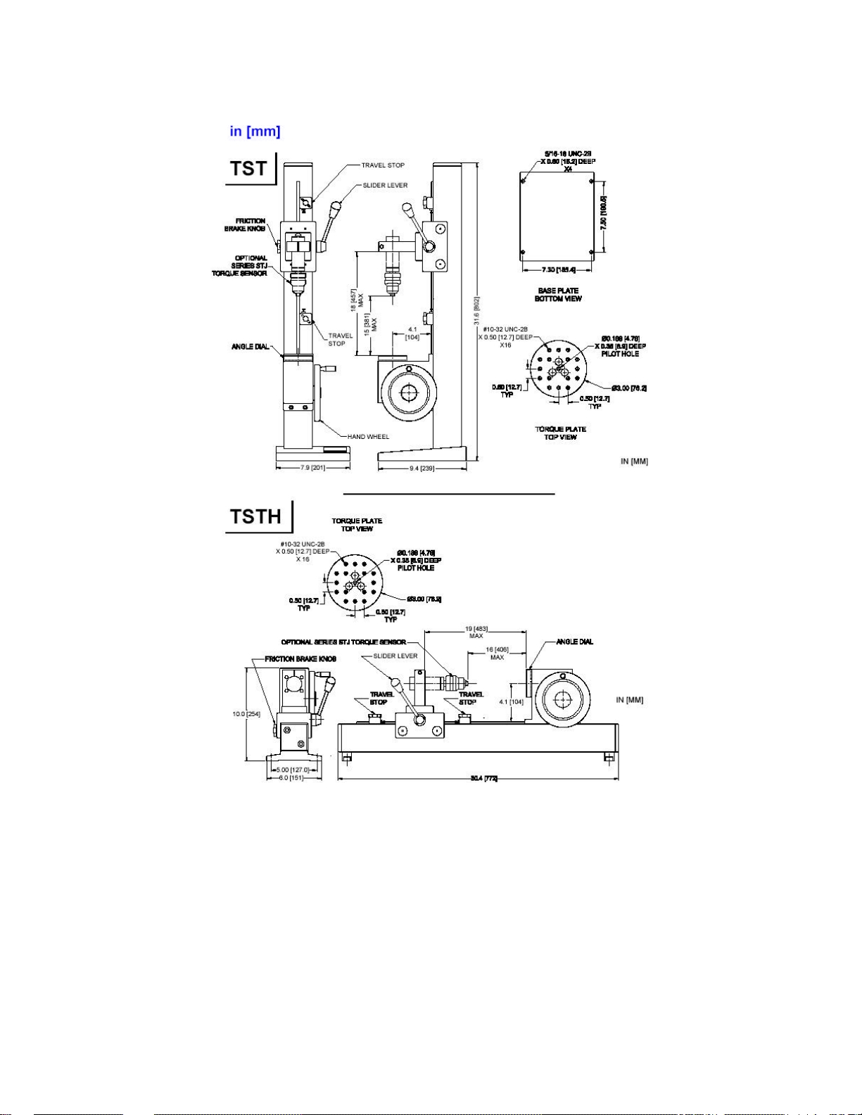
DIMENSIONS
MODELS TSTM/TSTMH
SAFETY TIPS
• Wear eye and face protection when testing. Although the TSTM/TSTMH has relatively
slow moving mechanisms, be aware of the dangers posed by potential energies that
can accumulate in the sample during testing.
• Keep away from the moving parts of the test stand.
CF 128 3 01/05
Page 6

• Never operate the test stand if there is any visible damage to the power cord or the
control unit. The TSTM/TSTMH is powered by 110/220 volts that are present in both
the power cord and the Control Unit. Any contact with this high voltage can cause
serious injury or even death.
• Ensure that the control unit be kept away from water or any other liquids at all times.
• Make sure the electrical outlet powering the test stand has local earth ground (3-hole
outlet).
• If it is necessary to remove the cover of the Control Unit or motor drive, always
disconnect power before doing so. Use Cooper replacement parts, only, if any repairs
are needed.
SETUP
1. Mount the test stand to a firm, flat, and level working surface for maximum safety
and accuracy using four 5/16 screws (not included). Use the included mounting hole
drill template to accurately drill the holes. Testing can take place without securing the
test stand in such a manner; however, it is strongly recommended that the stand be
secured, especially for high torque tests.
With the base or legs of the TSTM / TSTMH removed, the test stand can be easily
integrated into large systems such as production lines. In general, any mounting angle
is feasible.
The angle dial is adjustable relative to the torque plate. Turn the dial by hand to the
desired angle.
The travel stops’ positions can also be adjusted. Loosen the wing nuts, adjust to the
desired positions, and retighten.
2. Install an appropriate sensor onto the slider bracket. An indicator bracket that
mounts onto the test stand column is available separately.
3. Install any required attachments, grips, adapters, and other items necessary for
your test sample. Ensure that these items are set up in a secure and safe manner.
4. Plug the Control Unit cable into the 9-pin male connector located adjacent to the
motor, then plug the power cord into the control unit and the other end into an
electrical outlet with earth ground.
5. Turn on the power switch, located on the Control Unit beside the power cord in the
rear of the unit. If applicable, connect the indicator to a computer or printer.
6. Recheck to ensure the sample is secured properly. The TSTM/TSTMH is now ready
for use.
OPERATION
The slider’s position is adjustable along the column in order to engage and disengage the test
sample. Move the slider lever clockwise to lower the slider’s position closer to the torque
CF 128 4 01/05
Page 7

plate. The slider may be locked into position by tightening the friction brake knob located on
the opposite side of the slider.
The test stand may be operated by motor or by hand. To begin a motorized test, use the
Control Unit to operate the test stand (see instructions on the next page). For fine manual
adjustment turn the knob on the motor drive in the desired direction.
Using the Control Unit
CCW
Press and hold for counter-clockwise motion, release button to stop. Located on the face of
the Control Unit.
CW
Press and hold for clockwise motion, release button to stop. Located on the face of the
Control Unit.
SPEED CONTROL DIAL
Adjust speed by turning the dial 0.3 – 8.6 RPM (4 – 52º/s). Located on the face of the Control
Unit.
POWER SWITCH
Use this switch, in the l eft rear of the Control Unit, to turn on and turn off power to the test
stand. Power is indicated by an amber light on the face of the Control Unit.
POWER PLUG RECEPTACLE
Located in the left rear of the Control Unit. Plug the power cord in here.
CONTROL CABLE
Plug this cable into the lower male connector on the test stand, adjacent to the motor.
SPECIFICATIONS
Load capacity 100 lbin [11.3 Nm]
Speed range 0.3 – 8.6 RPM (4 – 52º/s)
Speed variation with load ±0% (Stepper motor driven)
Maximum angular travel No limit
Manual adjustment 12º/knob rev
Angle indicator resolution 2º
Maximum slider travel 15.50” [394 mm]
Slider travel rate 1.05” [26.6 mm] / lever rev
Line voltage Universal input 80-240 VAC, 50/60 Hz
Fuse type 1.2 A, 250V, 3AG SLO BLO
Weight (test stand, only) TSTM: 35.5 lb [16.1 kg]
TSTMH: 29.5 lb. [13.4 kg]
Control Unit weight 2.7 lb [1.2 kg]
CF 128 5 01/05
Page 8
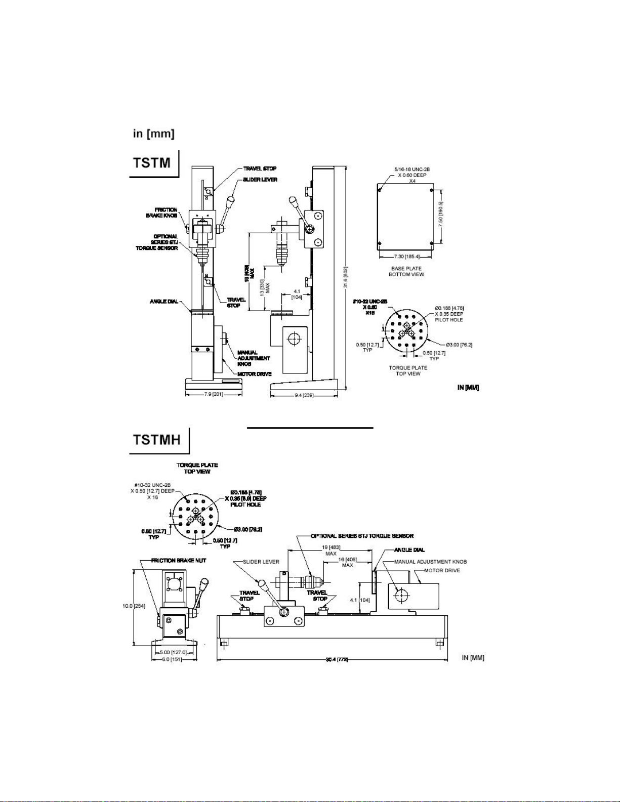
DIMENSIONS
CF 128 6 01/05
 Loading...