

Page 1

SERIES TSF/TSFM500/TSFH/TSFM500H
TEST STANDS
USER’S GUIDE
http://www.cooperinstruments.com
TEL (540) 349-4746 • FAX (540) 347-4755
Page 2
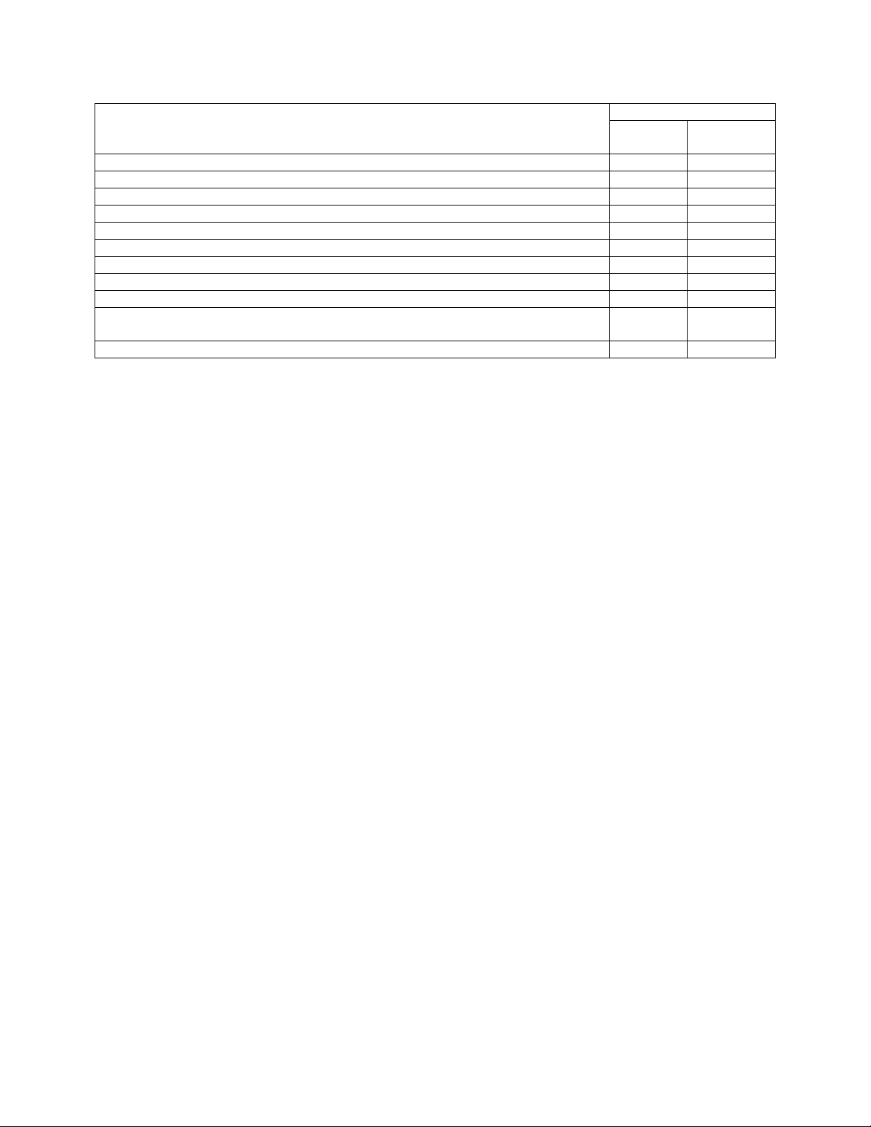
LIST OF INCLUDED ITEMS
Quantity
Item
Force measurement test stand 1 1
User’s Guide 1 1
Base 1 Mounting leg - 2
Column cap 1 2
5/16-18 x 1” screw for base installation 4 1/4-20 x 3/4" screw for top cap installation 2 4
Thumb screw for gauge mounting 4 4
Mounting hole drill template 1 Attachment kit – includes three hooks (small, medium, and large), 2” and 3”
diameter compression plates, and two couplers (#10-32 and 5/16-18)
Tool kit 1 1
TSF/
TSFM500
1 1
TSFH/
TSFM500H
UNPACKING AND SETTING UP
1. Carefully unpack the test stand from the box and inspect for any damage. Check the contents to
ensure that you have received a test stand complete with all accessories – see the list of included
items above.
2. Remove the foam from the middle portion of the test stand column and remove the plywood caps by
unscrewing the pair of screws at each end. For model TSF and TSFM500, install the base with four
5/16-18 x1” screws and the top cap with two 1/4-20 x 3/4" screws. For model TSFH and TSFM500H,
install the two column caps with two 1/4-20 x 3/4" screws each. Store all packaging materials for
possible future use.
3. Place the stand on a firm, flat and level working surface free from vibration to ensure accurate
readings. It is recommended that the test stand can be secured to a workbench – see your model’s
“Operation” section for further details.
TSFM500/TSFM500H
SAFETY TIPS
• Wear eye and face protection when testing. Although the test stand has relatively slow moving
mechanisms, be aware of the dangers posed by potential energies that can accumulate in the sample
during testing.
• Keep away from the moving parts of the test
• Never operate the test stand if there is any visible damage to the power cord or the control unit. The
test stand is powered by 110/220 volts that are present in both the power cord and the control unit. Any
contact with this high voltage can cause serious injury or even death.
• Ensure that the control unit be kept away from water or any other electrically conductive liquids at all
times.
• Make sure the electrical outlet powering the test stand has local earth ground (3-hole outlet).
• Do not remove the cover of the control unit or motor drive unless instructed to do so by a Cooper
representative. Always disconnect power before removing the cover. Use Cooper replacement parts,
only, if any repairs are needed.
SETUP
Place the stand on a clean, flat and level work area that meets the criteria outlined in the work area safety
instructions. For accurate readings, the area should be free of vibrations.
If desired, the stand can be mounted to the work area with two 5/16 screws. Included is a mounting hole
drill template for quick setup. Before the stand can be mounted, the belt cover surrounding the fine
adjustment knob on the right hand side of the stand has to be removed. Using a flat screwdriver, loosen
the four captive screws and slide off the cover.
CF 141 2 32-1032 REV 1 0405
Page 3

After the two 5/16 screws holding the stand are tight, place the belt cover back into place. While making
sure that there is no contact with the fine adjustment knob, tighten the screws in the four corners.
With the base removed, the test stand can be easily integrated into large systems such as production
lines. In general, the stand can be mounted on any angle (upside down, for example), although extra care
should be taken during installation and operation.
After the stand is in a stable and secure position, install a force gauge with four thumb screws (provided).
All Cooper gauges mount directly without adapters.
Plug the control unit cable into the 9-pin male connector located above the motor in the rear of the stand.
Plug the power cord into the remote console and the other end into a wall outlet.
Turn on the power with the switch located on the control unit beside the power cord.
The test stand is now ready for operation.
OPERATION
1. Mount the test stand to a firm, flat, and level working surface for maximum safety and accuracy using
four 5/16 screws (not included). Use the included mounting hole drill template to accurately drill the
holes. Testing can take place without securing the test stand in such a manner, however, it is strongly
recommended that the stand be secured.
2. Install a force gauge onto the gauge plate with four thumb screws. All Cooper force gauges mount
directly to the stand without adapters.
3. Install any required attachments, including grips, adapters, and other materials necessary for your
test sample. Make sure these items are set up in a secure and safe manner.
4. Power on the control unit (further instructions to follow). For fine adjustment or otherwise manual
testing, turn the knob on the right hand side of the stand clockwise for compression, counterclockwise
for tension.
The gauge bracket’s height can be adjusted along the column. Loosen the four screws that secure the
bracket to the column, adjust to the desired height, and retighten the screws.
Note: To maintain smooth operation of the test stand, avoid overloads and repetitive shock loads.
Optional Equipment
Digital Travel Display Kit
This travel indicator has a 5-digit display (0.0005” [0.01 mm] resolution) and a computer interface for
automated data collection. If purchased at the same time as the test stand, no setup is needed.
Otherwise, it may be easily installed by the user.
Limit Switches
Adjust the switches’ vertical positions by loosening and re-tightening the wing screws. A limit condition is
indicated by an amber light on the front surface of each sensor.
Upper limit switch – while a limit condition exists, the slider will not move up
Lower limit switch – while a limit condition exists, the slider will not move down
Using the Control Unit
UP
Press and hold for tension, release button to stop motion. Located on the face of the Control Unit.
DOWN
Press and hold for compression, release button to stop motion. Located on the face of the Control Unit.
SPEED CONTROL DIAL
Adjust speed by turning the dial 0.2 – 5.5 in/min [5 – 140 mm/min]. Located on the face of the Control
Unit.
CF 141 3 32-1032 REV 1 0405
Page 4

POWER SWITCH
Use this switch, in the left rear of the Control Unit, to turn on and turn off power to the test stand. Power is
indicated by an amber light on the face of the Control Unit.
POWER PLUG RECEPTACLE
Located in the left rear of the Control Unit. Plug the power cord in here.
CONTROL CABLE
Plug this cable into the lower male connector on the test stand, adjacent to the motor.
SPECIFICATIONS
Load capacity 500 lbF [2.2 kN]
Speed range 0.2 - 5.5 in/min [5 - 140 mm/min]
Maximum travel
Speed variation with load
Power Universal input, 80 - 240 VAC, 50/60 Hz
Fuse type 1.2A, 250V, 3AG SLO BLO
Weight (test stand only) TSFM500: 36 lb [16.3 kg]
Control unit weight 2.7 lb [1.2 kg]
4” [102 mm]
±0% (Stepper motor driven)
TSFM500H: 30 lb [13.6 kg]
DIMENSIONS
IN [MM]
CF 141 4 32-1032 REV 1 0405
Page 5

TSF/TSFH
OPERATION
1. Mount the test stand to a firm, flat, and level working surface for maximum safety and accuracy using
four 5/16 screws (not included). Use the included mounting hole drill template (vertical model only) to
accurately drill the holes. Testing can take place without securing the test stand in such a manner,
however, it is strongly recommended that the stand be secured, especially for large forces.
2. Install a force gauge onto the gauge plate with four thumbscrews. All Cooper force gauges mount
directly to the stand without adapters.
3. Install any required attachments, including grips, adapters, and other materials necessary for your
test sample. Make sure these items are set up in a secure and safe manner.
4. Begin the test by turning the hand wheel clockwise for compression or counter-clockwise for tension.
The gauge bracket’s height can be adjusted along the column. Loosen the four screws that secure the
bracket to the column, adjust to the desired height, and retighten the screws.
Note: To maintain smooth operation of the test stand, avoid overloads and repetitive shock loads.
OPTIONAL EQUIPMENT
Digital Travel Display Kit
This travel indicator has a 5-digit display (0.0005” [0.01 mm] resolution) and a computer interface for
automated data collection. If purchased at the same time as the test stand, no setup is needed.
Otherwise, it may be easily installed by the user.
SPECIFICATIONS
Load capacity 1000 lb [4500 N]
Maximum travel 4” [102 mm]
Travel rate 0.013” [0.34 mm]/rev
Weight (test stand only) TSF: 33 lb [14.5 kg], TSFH: 27 lb [12.3 kg]
CF 141 5 32-1032 REV 1 0405
Page 6

DIMENSIONS
IN [MM]
WARRANTY REPAIR POLICY
Limited Warranty On Products
Any Cooper Instruments product which, under normal operating conditions, proves defective in material
or in workmanship within one year of the date of shipment by Cooper will be repaired or replaced free of
charge provided that a return material authorization is obtained from Cooper and the defective product is
sent, transportation charges prepaid, with notice of the defect, and it is established that the product has
been properly installed, maintained, and operated within the limits of rated and normal usage.
Replacement or repaired product will be shipped F.O.B. from our plant. The terms of this warranty do not
extend to any product or part thereof which, under normal usage, has an inherently shorter useful life than
CF 141 6 32-1032 REV 1 0405
Page 7

one year. The replacement warranty detailed here is the buyer’s exclusive remedy, and will satisfy all
obligations of Cooper whether based on contract, negligence, or otherwise. Cooper is not responsible for
any incidental or consequential loss or damage which might result from a failure of any and all other
warranties, express or implied, including implied warranty of merchantability or fitness for particular
purpose. Any unauthorized disassembly or attempt to repair voids this warranty.
Obtaining Service Under Warranty
Advance authorization is required prior to the return to Cooper Instruments. Before returning the item,
contact the Repair Department c/o Cooper Instruments at (540) 349-4746 for a Return Material
Authorization number. Shipment to Cooper shall be at buyer’s expense and repaired or replacement
items will be shipped F.O.B. from our plant in Warrenton, Virginia. Non-verified problems or defects may
be subject to a $100 evaluation charge. Please return the original calibration data with the unit.
Repair Warranty
All repairs of Cooper products are warranted for a period of 90 days from date of shipment. This warranty
applies only to those items that were found defective and repaired; it does not apply to products in which
no defect was found and returned as is or merely recalibrated. It may be possible for out-of-warranty
products to be returned to the exact original specifications or dimensions.
* Technical description of the defect: In order to properly repair a product, it is absolutely necessary for
Cooper to receive information specifying the reason the product is being returned. Specific test data,
written observations on the failure and the specific corrective action you require are needed.
CF 141 7 32-1032 REV 1 0405
 Loading...