

Page 1

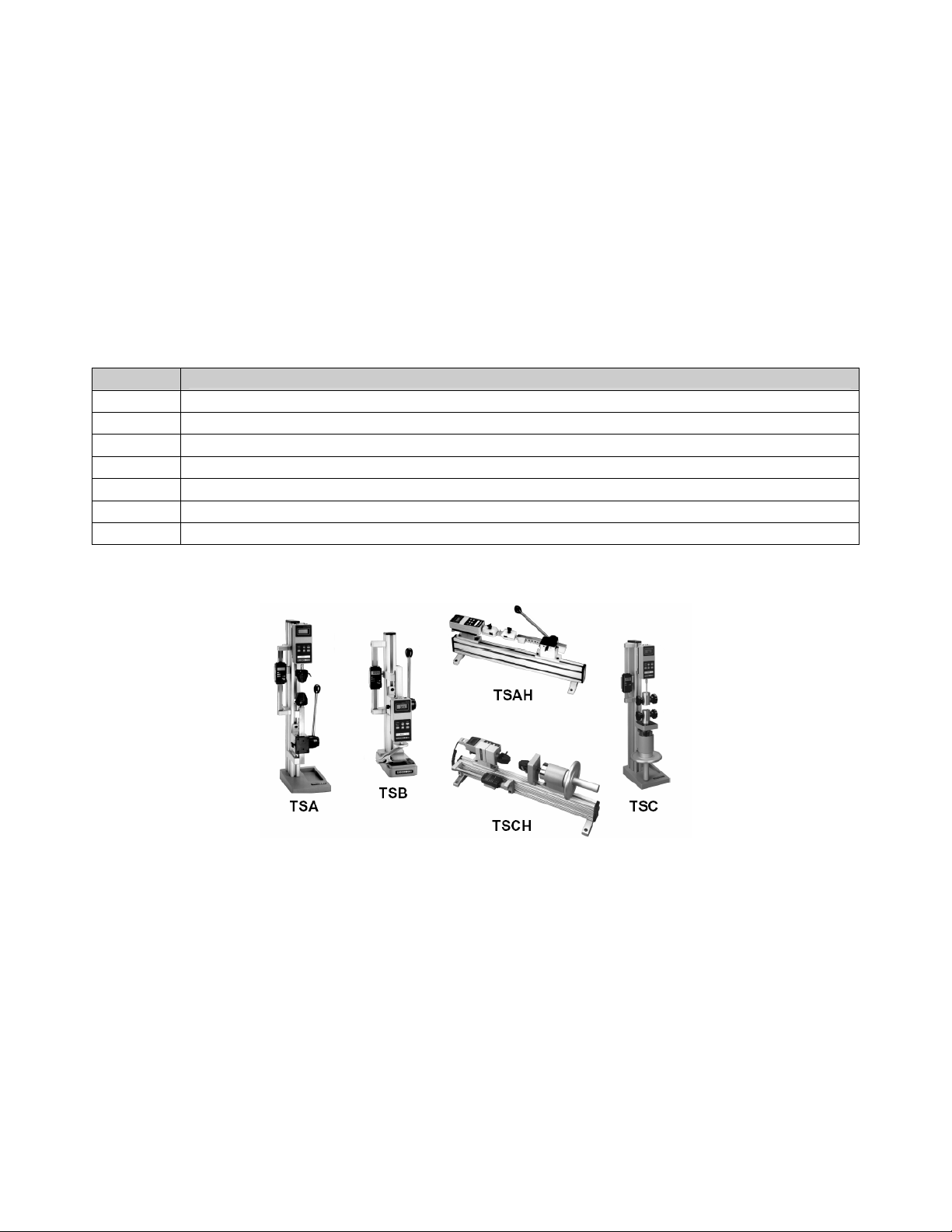
TS SERIES TEST STANDS –
TSA, TSAH, TSB, TSC, TSCH
www.cooperinstruments.com
PH: 540-349-4746 FAX: 540-347-4755
Page 2

CONTENTS
UNPACKING AND SETTING UP .................................................................................................1
LIST OF INCLUDED ITEMS.........................................................................................................1
TSA / TSAH OPERATION ............................................................................................................1
TSB OPERATION.........................................................................................................................4
TSC / TSCH OPERATION............................................................................................................5
WARRANTY REPAIR POLICY.....................................................................................................7
CF56 TS Series Test Stands ii 3/27/06 (V-0304 REV 3)
Page 3
UNPACKING AND SETTING UP
• Carefully unpack the stand and inspect for any damage. Check to make sure you have received a complete
test stand with all accessories – see the “List of included items” section.
• Install the loading lever on models TSA, TSAH and TSB. The position of the loading lever can be adjusted as
required – see the “Operation” section for your particular model. No assembly is required for Models TSC and
TSCH.
• Place the stand on a firm, flat and level working surface free from vibration to ensure accurate readings. It is
recommended that the test stand be secured to a work bench – see the “Operation” section for your particular
model.
LIST OF INCLUDED ITEMS
Quantity
1
4
4
1
1
1
1
Item
Force measurement stand
# 6-32 thumb screws for gauge mounting
#10-32 thumb screws (all models except TSB)
User’s Guide (this document)
Mounting hole drill template (except horizontal units)
Tool kit (all models except TSB)
Attachment kit (all models except TSB)– includes 2 hooks and a 2” diameter compression plate
TSA / TSAH OPERATION
1. Mount the test stand to a firm, flat, and level working surface for maximum safety and accuracy using four 5/16
screws (not included). Use the included mounting hole drill template to accurately drill the holes. Testing can
take place without securing the test stand in such a manner; however, it is strongly recommended that the
stand be secured, especially for large forces.
2. Install a force gauge onto the gauge plate with four thumb screws. Cooper force gauges mount directly to the
stand without adapters.
3. Install any needed attachments, including grips, adapters, and other materials necessary for your test sample.
Make sure these items are set up in a secure and safe manner.
4. Zero out the force gauge, then begin the test by turning the handwheel clockwise for compression or counterclockwise for tension.
CF56 TS Series Test Stands 1 3/27/06 (V-0304 REV 3)
Page 4

The loading lever can be adjusted to allow for ease of operation. Reposition the loading lever by removing the
knob and realigning the lever pin in the mounting hub. Move the loading lever clockwise for compression, counterclockwise for tension.
The rack brake can be set by loosening the wing nut, positioning the rack to the desired location and re-tightening
the wing nut.
The clearance on the rack can be set by adjusting the four set screws using the tool provided.
The travel stops can be adjusted in “0.5” [12.7mm] increments along the rack by moving the blocks to the desired
location and tightening two screws. Fine adjustments can be made using adjusting screws on the housing and
locking the jam nuts.
Note: To maintain smooth functioning of the stand, avoid overloads and repetitive shock loads.
TSA / TSAH SPECIFICATIONS
Load Capacity 750 lbs (3750 N)
Maximum travel 6” / 3.75” with stops (152.4 mm / 95.3 mm], with stops
Loading method/rate Rack & pinion / 3” (76.2 mm) per rev.
Weight (test stand only) TSA: 16 lbs (7.3 kg), TSAH: 13 lbs (5.9 kg)
Digital travel display resolution (optional) 0.0005” (0.01 mm)
CF56 TS Series Test Stands 2 3/27/06 (V-0304 REV 3)
Page 5

DIMENSIONS
In [mm]
CF56 TS Series Test Stands 3 3/27/06 (V-0304 REV 3)
Page 6

TSB OPERATION
1. Mount the test stand to a firm, flat, and level working surface for maximum safety and accuracy using four 5/16
screws (not included). Use the included mounting hole drill template to accurately drill the holes. Testing can
take place without securing the test stand in such a manner; however, it is recommended that the stand be
secured.
2. Install a force gauge onto the gauge plate with four thumb screws. Cooper force gauges mount directly to the
stand without adapters.
3. Install any needed attachments, including grips, adapters, and other materials necessary for your test sample.
Make sure these items are set up in a secure and safe manner.
4. Zero out the force gauge, then begin the test by turning the hand wheel clockwise for compression or counterclockwise for tension.
The loading lever can be adjusted to allow for ease of operation. Reposition the loading lever by removing the knob
and realigning the lever pin in the mounting hub. Move the loading lever clockwise for compression, counterclockwise for tension.
The rack brake can be set by loosening the wing nut, positioning the rack to the desired location and re-tightening
the wing nut.
The clearance on the rack can be adjusted by removing the gauge plate, aligning the C-bracket holes with the set
screws and adjusting as necessary.
Note: To maintain smooth functioning of the stand, avoid overloads and repetitive shock loads
TSB SPECIFICATIONS
Load Capacity 100 lbs (500 N)
Maximum travel
Loading method/rate
6” / 3.75” with stops
[152.4 mm / 95.3 mm]
Rack & pinion
3” (76.2mm) per rev
Weight (test stand only) 12 lbs (5.4 kg)
Digital travel display resolution (optional) 0.0005“ [0.01 mm]
CF56 TS Series Test Stands 4 3/27/06 (V-0304 REV 3)
Page 7

DIMENSIONS
In [mm]
TSC / TSCH OPERATION
1. Mount the test stand to a firm, flat, and level working surface for maximum safety and accuracy using four 5/16
screws (not included). Use the included mounting hole drill template to accurately drill the holes (TSC, only).
Testing can take place without securing the test stand in such a manner; however, it is strongly recommended
that the stand be secured, especially for large forces.
2. Install a force gauge onto the gauge plate with four thumb screws. Mark-10 force gauges mount directly to the
stand without adapters.
3. Install any needed attachments, including grips, adapters, and other materials necessary for your test sample.
Make sure these items are set up in a secure and safe manner.
4. Zero out the force gauge, then begin the test by turning the hand wheel clockwise for compression or counterclockwise for tension.
Note: To maintain smooth functioning of the stand, avoid overloads and repetitive shock loads.
TSC / TSCH SPECIFICATIONS
Load Capacity 1000 lbs (5000 N)
Maximum travel 3.5” (88.9 mm)
Loading method/rate
Weight (test stand only) TSC: 25 lb [9.0 kg], TSCH: 20 lb [11.3 kg]
Digital travel display (optional) Resolution ”0.0005” (0.01 mm)
Handwheel
0.1” (2.54 mm) per rev.
CF56 TS Series Test Stands 5 3/27/06 (V-0304 REV 3)
Page 8

DIMENSIONS
In [mm]
CF56 TS Series Test Stands 6 3/27/06 (V-0304 REV 3)
Page 9

WARRANTY REPAIR POLICY
Limited Warranty on Products
Any Cooper Instruments product which, under normal operating conditions, proves defective in material or in
workmanship within one year of the date of shipment by Cooper will be repaired or replaced free of charge provided
that a return material authorization is obtained from Cooper and the defective product is sent, transportation
charges prepaid, with notice of the defect, and it is established that the product has been properly installed,
maintained, and operated within the limits of rated and normal usage. Replacement or repaired product will be
shipped F.O.B. from our plant. The terms of this warranty do not extend to any product or part thereof which, under
normal usage, has an inherently shorter useful life than one year. The replacement warranty detailed here is the
buyer’s exclusive remedy, and will satisfy all obligations of Cooper whether based on contract, negligence, or
otherwise. Cooper is not responsible for any incidental or consequential loss or damage which might result from a
failure of any and all other warranties, express or implied, including implied warranty of merchantability or fitness for
particular purpose. Any unauthorized disassembly or attempt to repair voids this warranty.
Obtaining Service under Warranty
Advance authorization is required prior to the return to Cooper Instruments. Before returning the item, contact the
Repair Department c/o Cooper Instruments at (540) 349-4746 for a Return Material Authorization number.
Shipment to Cooper shall be at buyer’s expense and repaired or replacement items will be shipped F.O.B. from our
plant in Warrenton, Virginia. Non-verified problems or defects may be subject to a $100 evaluation charge. Please
return the original calibration data with the unit.
Repair Warranty
All repairs of Cooper products are warranted for a period of 90 days from date of shipment. This warranty applies
only to those items that were found defective and repaired; it does not apply to products in which no defect was
found and returned as is or merely recalibrated. It may be possible for out-of-warranty products to be returned to
the exact original specifications or dimensions.
* Technical description of the defect: In order to properly repair a product, it is absolutely necessary for Cooper to
receive information specifying the reason the product is being returned. Specific test data, written observations on
the failure and the specific corrective action you require are needed.
CF56 TS Series Test Stands 7 3/27/06 (V-0304 REV 3)
 Loading...