

Page 1
TMV 500 BA VERTICAL MOTORIZED TEST STAND USER’S GUIDE
INTRODUCTION
The TMV 500 Vertical Motorized Test Stand assures consistent, identical measuring conditions by eliminating
possible human error.
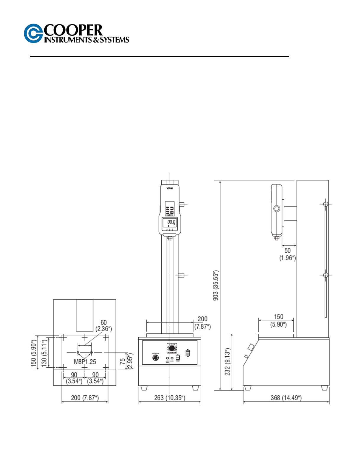
SPECIFICATIONS
Motorized Vertical Test Stand
Model No: TMV-500-BA (Basic Type)
Max Load: 500 lbs.
Speed: Standard 0.3” ~ 9.5”/minute
Optional High Speed: 1.0” ~ 31”/minute (others available)
Optional Slow Speed: 0.2” ~ 4”/minute
Stroke: Approx 16"
Weight: Approx 66 lbs
Dimensions: 36"Hx 10"W x l5"D
Power: 115 VAC
CF 173 1 07/03
Page 2
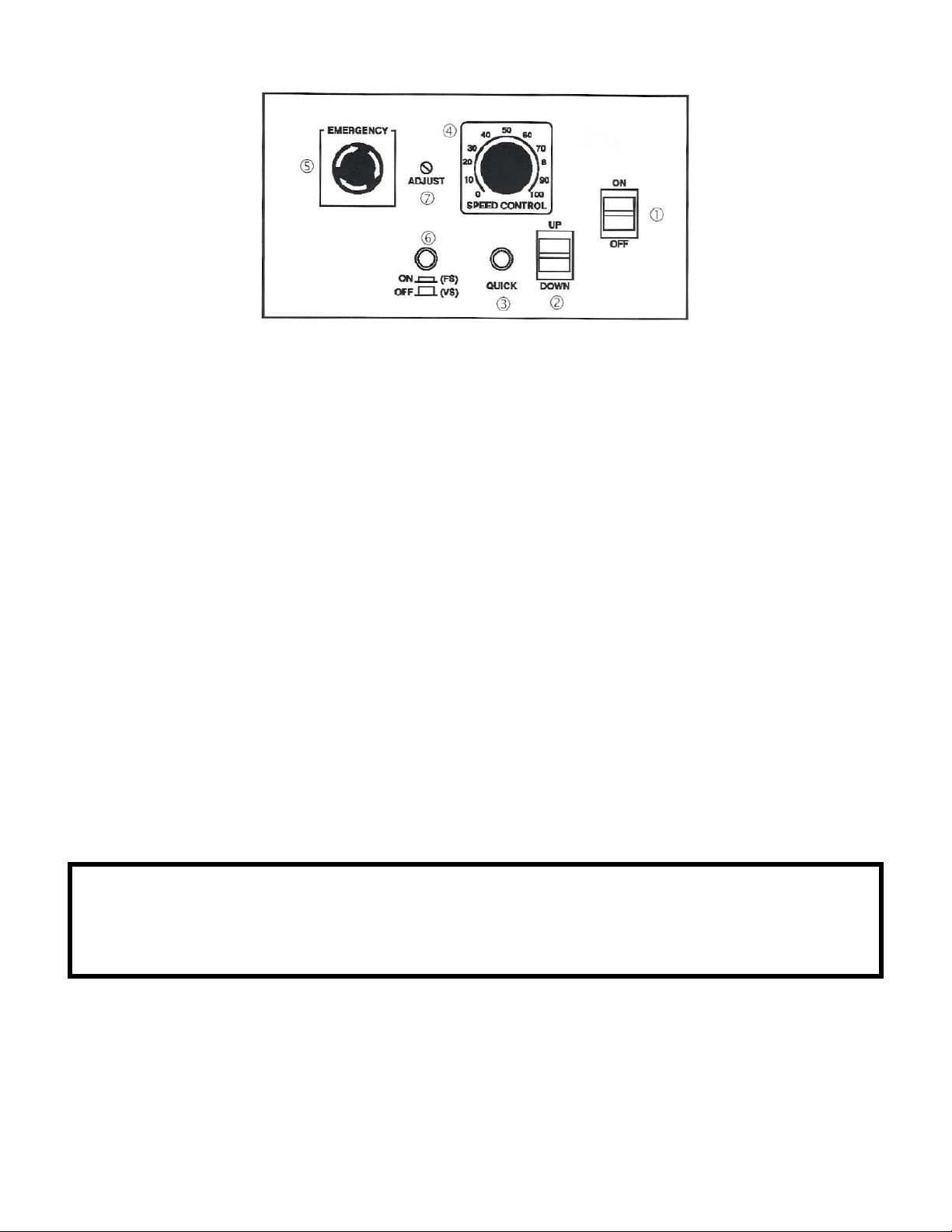
CONTROL PANEL
(1) Power Switch (5) Emergency Stop Switch
(2) Direction Switch (6) Speed Mode Switch
(3) Quick Switch (7) Fixed Speed Adjustment Screw
(4) Speed Adjust Knob
GENERAL OPERATION
1. Make sure of the following before plugging the power cord into the 115VAC output.
A. Turn Speed Adjustment Knob (4) to 50 (middle speed).
B. Turn Emergency Switch (5) clockwise to release the stop (to set operatio n).
C. To allow operation, move the upper and lower limit switches so that there will be a separation
between them. (For the upper and lower limit switch, see figure below).
2. Attach Plug power cord to stand and plug into 115VAC outlet.
3. Turn Power Switch (1) on. Red power lamp will light.
4. When the Direction Switch (2) is pressed up, the Head goes up to the upper travel limit. When the
Direction Switch (2) is pressed down, the Head goes down to the lower travel limit. (The travel limit
positions are adjustable.)
5. Select desired test speed:
A. Variable Speed Mode: Release (6) Speed Mode Switch to out (off) position (Red light oft). Adjust
the speed of the movement by turning the Speed Adjust Knob (4).
B. Fixed Speed Mode: Push (6) Speed Mode Switch (Red light on). This will provide a constant
speed. Fixed speed can be adjusted by turning the Fixed Speed Adjustment Screw (7).
6. Regardless of preset speed, when the Quick Switch (3) is pressed, Head will move at maximum speed.
Emergency Brake Stop Switch
Push this Emergency Stop Switch (5) whenever you are in emergency situation. To re-engage the Emergency
Stop Switch (5), simply turn the switch clockwise.
***W A R N I N G***
Do Not Exceed 500 lbs. Capacity
Test samples can break or shatter, wear eye and body protection to avoid injury.
CF 173 2 07/03
Page 3

STROKE LIMITER
HEAD
UPPER TRAVEL LIMIT
Head stops going up when it reaches this position.
To adjust the stroke, loosen screw and move the
limit to desired position. Re-tighten screw securely.
LOWER TRAVEL LIMIT
Head stops going up when it reaches this position.
To adjust the stroke, loosen screw and move the
limit to desired position. Re-tighten screw securely.
CAUTION:
Make sure the lower limit is set high enough to
allow adequate clearance for the force gauge, so it
will not be overloaded.
WARRANTY REPAIR POLICY
Limited Warranty on Products
Any Cooper Instruments product which, under normal operating conditions, proves defective in material or in
workmanship within one year of the date of shipment by Cooper will be repaired or replaced free of charge provided
that a return material authorization is obtained from Cooper and the defective product is sent, transportation
charges prepaid, with notice of the defect, and it is established that the product has been properly installed,
maintained, and operated within the limits of rated and normal usage. Replacement or repaired product will be
shipped F.O.B. from our plant. The terms of this warranty do not extend to any product or part thereof which, under
normal usage, has an inherently shorter useful life than one year. The replacement warranty detailed here is the
buyer’s exclusive remedy, and will satisfy all obligations of Cooper whether based on contract, negligence, or
otherwise. Cooper is not responsible for any incidental or consequential loss or damage which might result from a
failure of any and all other warranties, express or implied, including implied warranty of merchantability or fitness for
particular purpose. Any unauthorized disassembly or attempt to repair voids this warranty.
Obtaining Service under Warranty
Advance authorization is required prior to the return to Cooper Instruments. Before returning the item, cont act the
Repair Department c/o Cooper Instruments at (540) 349-4746 for a Return Material Authorization number.
Shipment to Cooper shall be at buyer’s expense and repaired or replacement items will be shipped F.O.B. from our
plant in Warrenton, Virginia. Non-verified problems or defects may be subject to an evaluation charge. Please
return the original calibration data with the unit.
Repair Warranty
All repairs of Cooper products are warranted for a period of 90 days from date of shipment. This warranty applies
only to those items that were found defective and repaired; it does not apply to products in which no defect was
found and returned as is or merely recalibrated. It may be possible for out-of-warranty products to be returned to
the exact original specifications or dimensions.
* Technical description of the defect: In order to properly repair a product, it is absolutely necessary for Cooper to
receive information specifying the reason the product is being returned. Specific test data, written observations on
the failure and the specific corrective action you require are needed.
CF 173 3 07/03
 Loading...