

Page 1

QSC 484
LINE POWERED SIGNAL CONDITIONER
WITH ZERO CLAMPING AND AC OR DC
COUPLED OUTPUT
USER’S GUIDE
www.cooperinstruments.com
PH: (540) 349-4746 • FAX: (540) 347-4755
Page 2

CONTENTS
1.0 INTRODUCTION....................................................................................................... 1
2.0 DESCRIPTION.......................................................................................................... 1
3.0 OPERATION............................................................................................................. 2
4.0 SETTING THE CONSTANT CURRENT ................................................................... 3
4.0 MAINTENANCE AND REPAIR................................................................................. 4
5.0 SPECIFICATIONS .................................................................................................... 4
6.0 WARRANTY REPAIR POLICY................................................................................. 5
CF 102 ii 20141 rev. A
Page 3
1.0 INTRODUCTION
The QSC 484 Power Unit features four operating configurations:
• AC-Coupled Mode
• AC-Coupled Mode with Active Clamp
• AC-Coupled Mode with Relay Clamp
• DC-Coupled Mode
The unit supplies 2mA to 20mA of constant current to transducers or amplifiers, as well as deliver up to 10mA of
low impedance (50 ohms) output current via a unity gain buffer amplifier.
2.0 DESCRIPTION
AC-Coupled Mode (no clamp)
The AC-Coupled Mode is used for most normal measurements since long term thermal drifting of long time
constant transducers is nullified by the internal AC coupling. In this configuration the signal information (AC
voltage) is decoupled from the transducer bias level (DC voltage) and fed through a unity gain buffer amplifier.
The coupling time constant is approximately 1,000 seconds and is dependent of output load.
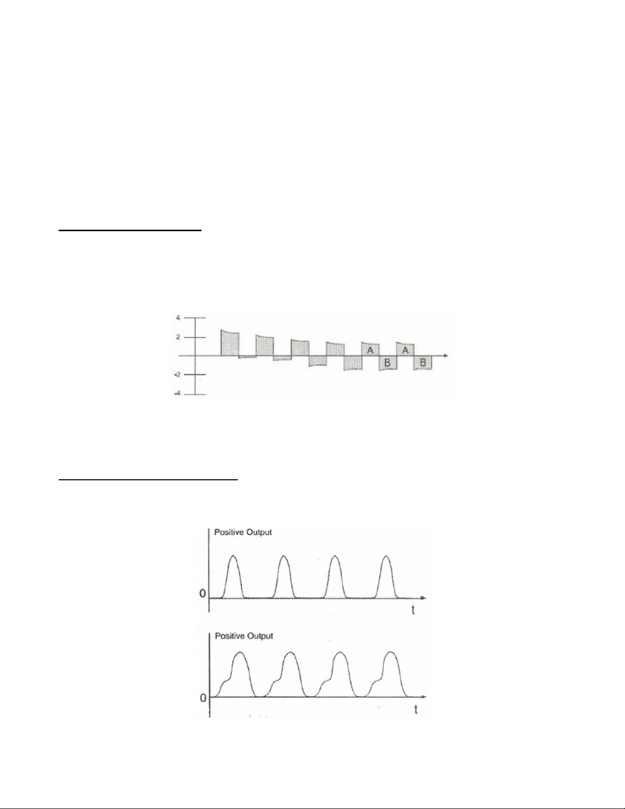
Since the output signal is not clamped, a repetitive pulse train will gradually drift downward and stabilize in time
with equal areas above and below signal ground (Figure 1).
Figure 1 – Repetitive Pulse Train, AC Signal
To operate in this mode, set the MODE switch to AC, and the CLAMP switch to the OUT position.
NOTE: The front panel ZERO ADJUST knob has no effect in any of the AC mode configurations.
AC-Coupled Mode with Active Clamp
In this configuration, the conditioner is internally set to automatically keep pulsating output signals ground based
(within 20mV negative undershoot) and positive polarity. (Figure 2) This clamp is useful in stabilizing output
signals when interfacing with instrumentation that requires repetitive pulse train signals be ground based and of
one polarity (usually positive).
Figure 2 – Positive Polarity, Zero-based AC Output
CF 102 1 20141 rev. A
Page 4

To operate in this mode, set the MODE switch to AC, and the CLAMP switch to the IN position.
AC-Coupled Mode with Relay Clamp
The Relay Clamp is essentially a perfect clamp with no negative undershoot. Grounding one wire of the relay
coil externally actuates the Relay Clamp. This grounding operation can be a manual switch, automatic by
machine operation or otherwise. The Relay Clamp may also be activated by pressing the front panel
CAL/OP/GND switch to the GND position.
To operate this mode, set the MODE switch to AC. The CLAMP switch position does not affect this function.
DC-Coupled Mode
In the DC-Coupled mode, the output signal is directly coupled from the transducer, through a level shifting
circuit, to the unity gain buffer amplifier. In this setting, the low frequency response is determined solely by the
transducer. The system discharge time constant is not comprised by the signal conditioner, so long time
constant transducers may be used for calibration purposes or for special situations where extra long duration
events must be measured. In the latter situation, a thermally stable environment is usually required.
To operate in this mode, set the MODE switch to DC. The CLAMP switch has no effect in this mode.
3.0 OPERATION
Standard Sensor
Cooper Force
Sensor
Cable
Cooper Sensor
Signal Conditioner
Output Cable
Readout
Device (not
supplied)
Figure 3 – Typical Sensor System
Operating in any AC-Coupled Mode
1. Connect the transducer or amplifier to the INPUT jack located on the back of the conditioner.
Note: Since transducer operate at a low impedance level, it is not necessary to use low noise or other
shielded cable. In some cases, it is desirable to use twisted pair and other types of 2-wire cable.
2. Connect readout device to the OUTPUT jack located on the back of the conditioner.
3. Set the MODE switch to AC.
4. Plug the supplied 3- line cord into a 120V 60Hz receptacle, then press the red POWER button on. Activating
the power button supplies an adjustable constant current source at a regulated DC power supply (+24V)
and to the single transducer or amplifier.
5. Verify the transducer circuit is operating properly by observing the Fault Monitor Meter located on the front
panel. A normal operating transducer will display in the green range, approximately mid-scale of the meter
indicator. A reading in the red (zero volts) range indicates a short in the cabling and/or the amplifier. A
reading in the yellow (full-scale) range indicates an open in the cabling or a faulty amplifier.
6. Activate the GND Switch (Relay Clamp) to quickly stabilize the output to zero. This will immediately charge
the capacitor in the AC coupling circuit to the transducer bias.
7. Set the CLAMP Switch to the desired position.
8. Allow the unit to warm up for 10 or 15 minutes prior to use to thermally stabilize system components.
9. To conduct a system calibration, press the CAL/OP/GND switch to the CAL position to introduce a +1.0 volt
DC calibration voltage to the input of the unity gain output amplifier. A BNC CAL input jack is available on
the back panel of the unit for external calibration purposes.
CF 102 2 20141 rev. A
Page 5

Figure 4 – Panel Descriptions
Operating in DC-Coupled Mode
1. Connect the transducer or amplifier to the INPUT jack located on the back of the conditioner.
Note: Since transducer operate at a low impedance level, it is not necessary to use low noise or other
shielded cable. In some cases, it is desirable to use twisted pair and other types of 2-wire cable.
2. Connect readout device to the OUTPUT jack located on the back of the conditioner.
3. Set the MODE switch to DC.
4. Plug the supplied 3- line cord into a 120V 60Hz receptacle, then press the red POWER button on. Activating
the power button supplies a regulated DC power supply (+24V) and adjustable constant current source to
the single transducer or amplifier.
5. Verify the transducer circuit is operating properly by observing the Fault Monitor Meter located on the front
panel. A normal operating transducer will display in the green range, approximately mid-scale of the meter
indicator. A reading in the red (zero volts) range indicates a short in the cabling and/or the amplifier. A
reading in the yellow (full-scale) range indicates an open in the cabling or a faulty amplifier.
6. Allow the unit to warm up for 10 or 15 minutes prior to use to thermally stabilize system components.
7. Zero the output voltage. After the system has adequately warmed up, turn the ZERO ADJUST control knob
to zero the output voltage. Clockwise rotation shifts the voltage positive and counterclockwise moves it
negative. After long periods of operation, it may be necessary to reset the zero slightly. This is normal.
8. To conduct a system calibration, press the CAL/OP/GND switch to the CAL position to introduce a +1.0 volt
DC calibration voltage to the input of the unity gain output amplifier. A BNC CAL input jack is available on
the back panel of the unit for external calibration purposes.
4.0 SETTING THE CONSTANT CURRENT
System performance may be adversely affected by the physical parameters of the transducer, pulse rise time,
cable length and terminations. Optimizing the current setting may help correct this condition.
The optimum current setting is best determined by experimenting with your particular test set-up. A good rule of
thumb is to use the lowest current consistent with satisfactory results to minimize transducer self-heating and
lower noise.
NOTE: Unit is factory set to 4 ±0.6 mA. This current setting is sufficient for most applications.
To set the constant current,
1. Remove the 4 rubber feet from the bottom of the conditioner by unscrewing the pan head scres with a small
Phillips head screwdriver.
2. Pull the protective inner case out of the blue outer shell.
CF 102 3 20141 rev. A
Page 6

3. Remove the small flat head screw from the center of the protective inner case, near the edge.
4. Remove the cover from the protective case to expose the internal circuit board.
5. Locate the current adjust potentiometer. (Refer to Figure 5).
6. Connect a 0-30 mA DC meter (or multimeter) to the center conductor of the INPUT jack.
7. Return the negative probe to chassis ground. The constant current value is read directly on the milliameter.
8. Adjust the current adjust potentiometer to set current to a new level. Use care to avoid shorting components
with metal screwdriver blades.
9. Replace and fasten the protective case, outer shell, and rubber feet.
Caution: Operating a transducer or amplifier above 20mA may result in equipment damage.
Figure 5 – Constant Current Potentiometer Location
4.0 MAINTENANCE AND REPAIR
Aside from the transducer current adjustment as described in Section 3.0, there are no other adjustments to
perform on the QSC 484. No maintenance is required for these units and it is suggested that should trouble
occur, you contact the Cooper Instruments for assistance
5.0 SPECIFICATIONS
ELECTRICAL
Supply Voltage Regulated VDC +24 ±
Sensor Excitation Current (Constant Current Source) MA 2-20 (1)
Time Constant Sec 1,000 (3)
Transducer Bias Voltage Accommodation Range VDC 7.5 to 14.5
Low Frequency Response (-5%) AC, DC Hz 0.0005, 0 (4)
High Frequency Response (±
DC Offset mV < 30 (3)
Noise Broadband, RMS (1Hz- 10 kHz) µV (dB) 28.8 (-90,8)
Typical Spectral Noise: At 1 Hz µV/√hZ (dB) 4.50 (-107)
At 10 Hz µV/√hZ (dB) 1.10 (-119)
At 100 Hz µV/√hZ (dB) 0.40 (-129)
At 1 kHz µV/√hZ (dB) 0.20 (-135)
5V, -5%) kHz 200
1.0
CF 102 4 20141 rev. A
Page 7

At 10 kHz µV/√hZ (dB) 0.06 (-144)
Gain 1 ± 1%
Maximum Voltage Output Volts (pk) ± 10
Output Impedance Ohms < 10
Fault Monitor Meter (1 mA movement) V/FS 24 ± 1.0
Power (50 to 400 Hz) V/A
PHYSICAL
Connectors: Input (transducer) type BNC jack
Output (scope) type BNC jack
Calibration Input type BNC jack
Remote Ground type BNC jack
AC (power) input type IEC 320
Size (H x W x D) In. 2 x 5 x 10.5
(mm) (50.8 x 127 x 266.7)
Weight lb(gm) 2 (907.2)
Notes:
(1) Unit supplied with current set at 4 ±0.6 mA.
(2) Unit set to 230 VAC when ordered as “F484B02).
(3) In AC mode.
(4) System response determined by sensor’s discharge time constant.
115 ± 10%/0.25
(maximum)
(2)
6.0 WARRANTY REPAIR POLICY
Limited Warranty On Products
Any Cooper Instruments product which, under normal operating conditions, proves defective in material or in
workmanship within one year of the date of shipment by Cooper will be repaired or replaced free of charge
provided that a return material authorization is obtained from Cooper and the defective product is sent,
transportation charges prepaid, with notice of the defect, and it is established that the product has been properly
installed, maintained, and operated within the limits of rated and normal usage. Replacement or repaired
product will be shipped F.O.B. from our plant. The terms of this warranty do not extend to any product or part
thereof which, under normal usage, has an inherently shorter useful life than one year. The replacement
warranty detailed here is the buyer’s exclusive remedy, and will satisfy all obligations of Cooper whether based
on contract, negligence, or otherwise. Cooper is not responsible for any incidental or consequential loss or
damage which might result from a failure of any and all other warranties, express or implied, including implied
warranty of merchantability or fitness for particular purpose. Any unauthorized disassembly or attempt to repair
voids this warranty.
Obtaining Service Under Warranty
Advance authorization is required prior to the return to Cooper Instruments. Before returning the item, contact
the Repair Department c/o Cooper Instruments at (540) 349-4746 for a Return Material Authorization number.
Shipment to Cooper shall be at buyer’s expense and repaired or replacement items will be shipped F.O.B. from
our plant in Warrenton, Virginia. Non-verified problems or defects may be subject to a $100 evaluation charge.
Please return the original calibration data with the unit.
Repair Warranty
All repairs of Cooper products are warranted for a period of 90 days from date of shipment. This warranty
applies only to those items that were found defective and repaired; it does not apply to products in which no
defect was found and returned as is or merely recalibrated. It may be possible for out-of-warranty products to
be returned to the exact original specifications or dimensions.
* Technical description of the defect: In order to properly repair a product, it is absolutely necessary for Cooper
to receive information specifying the reason the product is being returned. Specific test data, written
observations on the failure and the specific corrective action you require are needed.
CF 102 5 20141 rev. A
Page 8

CF 102 6 20141 rev. A
 Loading...