

Page 1

SERIES MG
USER’S GUIDE
http://www.cooperinstruments.com
TEL (540) 349-4746 • FAX (540) 347-4755
Page 2

CONTROLS
The Series MG force gauges have three keys for controlling all functions of the instrument.
POWER
PEAK
ZERO
Turns the instrument on and off. It is also used to select an option in the setup mode
Used to select Tension Peak, Compression Peak or normal (real time) display mode.
The actual peak readings are always captured and can be displayed at any time.
Zeros any tare value (up to the full capacity of the gauge) and clears the peak readings
stored in memory.
DISPLAY
The display consists of a 4½ digit section and several indicators. Their functions are listed below.
LO BAT Low battery voltage indicator
C Compressive force indicator
T Tensile force indicator
C PEAK Peak compressive force indicator
T PEAK Peak tensile force indicator
LB,KG,N,G Units of measurement (model dependent)
- - (dashes) Overload (>110% of range)
OPERATION
The default mode of operation of the Series MG is the normal (real time) mode. Peak readings can be observed
as they occur by pressing PEAK until the desired mode (C PEAK or T PEAK) appears on the display. This
action affects only the display. The actual tensile and compressive peak readings are captured automatically
and retained until cleared by either pressing ZERO or shutting off the gauge. It is also equipped with an
automatic shutdown feature, which will shut off after a selected period of inactivity. The default setting is 30
minutes.
The displayed units of measurement, the mode of operation (peak or normal) and the automatic shutdown
settings can be changed by the following procedure:
To change the default mode of operation and the displayed units of measurement, hold PEAK while turning on
the power. Press PEAK repeatedly until “init” appears on the display. Press POWER. A flashing indicator will
show the present setting. Press PEAK repeatedly to scroll through the available choices and POWER to accept
the desired one. The flashing indicator will show the present units of measurement. Use PEAK to scroll through
the available choices and POWER to accept. Press POWER again at the “donE” prompt to save the changes.
To change the default shutdown setting of 30 minutes, hold PEAK while turning on the power. Press PEAK
repeatedly until ‘AOFF’ appears. Press POWER to select this function. The current setting will flash on the
display. Use the PEAK key to scroll through the displayed choices and POWER to select. Press POWER again
at the ‘donE’ prompt to save the changes.
If no changes have been made, exit the setup mode by momentarily inserting the power plug with the AC
adapter unplugged, or disconnect the battery. This action will terminate the setup mode without making any
changes to the previous settings.
POWER
The gauge may be powered by the interval 9V battery, or by the included AC adapter. PLEASE DO NOT
SUBSTITUTE OTHER ADAPTERS, SINCE A CONNECTION OF A POWER SOURCE WITH REVERSE
POLARITY WILL CAUSE SERIOUS DAMAGE TO THE INSTRUMENT. When a steady LOBAT appears on the
display, it indicates the last 10% of battery life. A flashing LO BAT indicated the need for immediate battery
replacement.
CALIBRATION
To properly calibrate this instrument, application of an exact load appropriate for your model will be required. It
must be in pounds as indicated by the model number. For example, the MG50 requires a 50 lb calibration
weight regardless of displayed units.
CF14 1 (V-0604 32-1007)
Page 3

While holding PEAK, turn on the gauge. Press PEAK repeatedly until ‘CAL’ appears on the display and press
POWER three times to select the calibration mode. At the ‘null’ prompt press ZERO. At the ‘SPAn’ prompt
apply your test weight and press POWER. The display will show “uuuu” (test weight is insufficient) or “nnnn”
(test weight is excessive). If this happens, terminate the calibration mode by momentarily inserting the power
plug with the AC adapter unplugged, or disconnect the battery. This will stop the calibration procedure without
making any changes to the previous calibration data.
A successful calibration is indicated by ‘donE’ on the display. Press POWER to save the changes and resume
normal operation.
Model Capacity x graduation
MG025 0.25 x 0.0002 lb, 100 x 0.1gF, 1 x 0.001 N
MG05 0.5 x 0.0005 lb, 250 x 0.2 gF, 2.5 x 0.002 N
MG2 2 x 0.002 lb, 1 x 0.001 kgF, 10 x 0.01 N
MG5 5 x 0.005 lb, 2.5 x 0.002 kgF, 25 x 0.02 N
MG10 10 x 0.01 lb, 5 x 0.005 kgF, 50 x 0.05 N
MG20 20 x 0.02 lb, 10 x 0.01 kgF, 100 x 0.01 N
MG50 50 x 0.05 lb, 25 x 0.02 kgF, 250 x 0.2 N
MG100 100 x 0.1 lb, 50 x 0.05 kgF, 500 x 0.5 N
MG200 200 x 0.2 lb, 100 x 0.1 kgF, 1000 x 1 N
MG500 500 x 0.5 lb, 250 x 0.2 kgF, 2500 x 2 N
MOUNTING
The instrument housing is reversible and may be rotated 180° for test stand mounting by unscrewing two screws
on the back, rotating the housing and reassembling. In addition to the #6-32 screws, a 0.188” {4.77 mm}
diameter load-carrying pin should be utilized so as not to stress the threads.
SPECIFICATIONS
ACCURACY ±0.5% of full-scale ±1 digit
SAMPLING RATE 30 readings/second
DISPLAY RATE 2.5/S in normal mode, 30/s in peak mode
SAFE OVERLOAD 150% of gauge capacity. Display shows “---“ (dashes) above 110%
POWER 9V battery or AC adapter
BATTERY LIFE 30 hours of continuous operation
SIZE
WEIGHT
3.7” x 2.5” x 1.5”
(94.0mm x 63.5mm x 38.1mm)
0.65 lb (0.3 kg) – all models except MG 500
0.87 lb (0.4 kg) – MG 500
CF14 2 (V-0604 32-1007)
Page 4
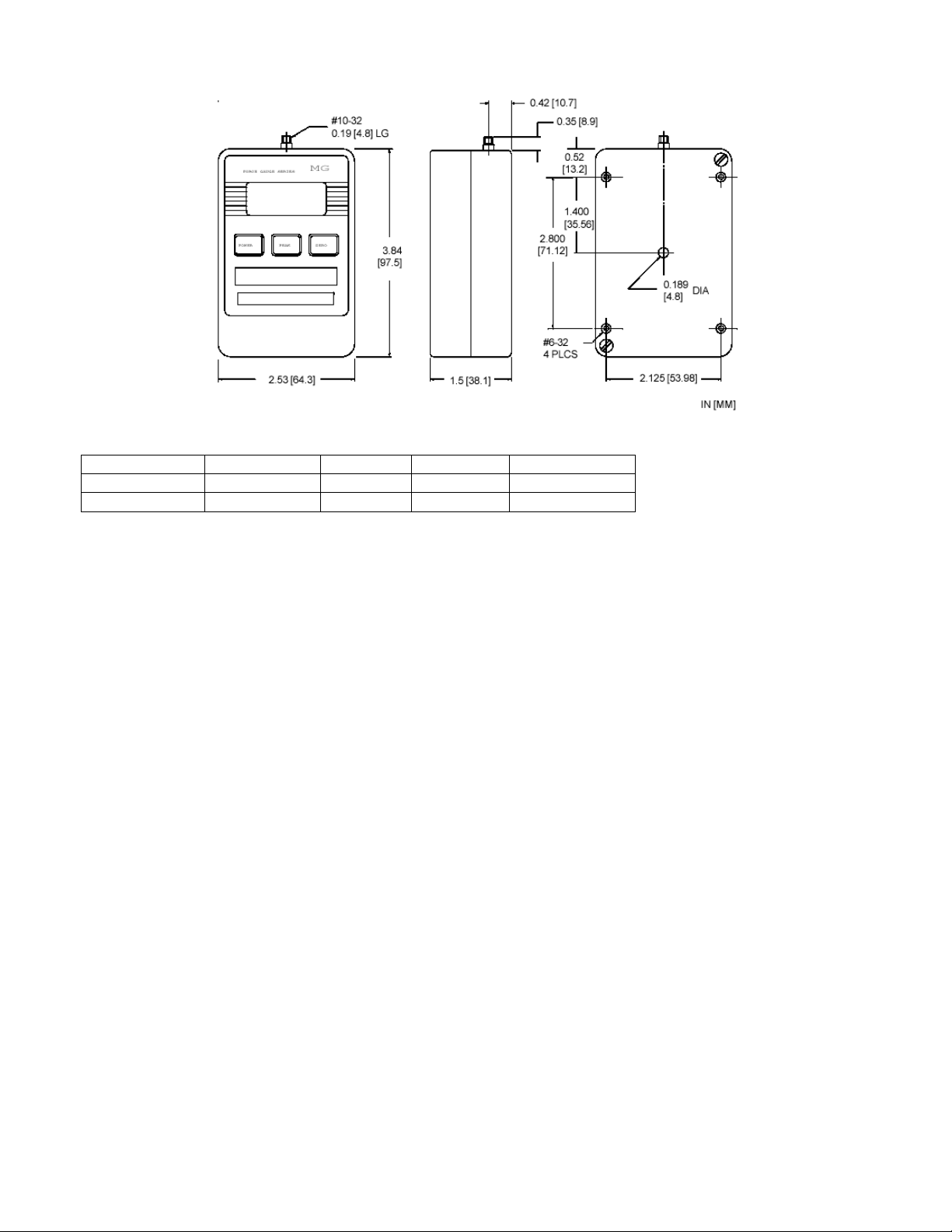
Dimensions
In [mm]
MODEL ØA B C THREAD
MG012-MG200 0.200 [5.8] 0.19 [4.8] 0.35 [8.9] #10-32
MG500 0.312 [7.9] 0.44 [11.2] 0.312 [7.9] 5/16-18
WARRANTY REPAIR POLICY
Limited Warranty On Products
Any Cooper Instruments product which, under normal operating conditions, proves defective in material or in
workmanship within one year of the date of shipment by Cooper will be repaired or replaced free of charge
provided that a return material authorization is obtained from Cooper and the defective product is sent,
transportation charges prepaid, with notice of the defect, and it is established that the product has been properly
installed, maintained, and operated within the limits of rated and normal usage. Replacement or repaired
product will be shipped F.O.B. from our plant. The terms of this warranty do not extend to any product or part
thereof which, under normal usage, has an inherently shorter useful life than one year. The replacement
warranty detailed here is the buyer’s exclusive remedy, and will satisfy all obligations of Cooper whether based
on contract, negligence, or otherwise. Cooper is not responsible for any incidental or consequential loss or
damage which might result from a failure of any and all other warranties, express or implied, including implied
warranty of merchantability or fitness for particular purpose. Any unauthorized disassembly or attempt to repair
voids this warranty.
Obtaining Service Under Warranty
Advance authorization is required prior to the return to Cooper Instruments. Before returning the item, contact
the Repair Department c/o Cooper Instruments at (540) 349-4746 for a Return Material Authorization number.
Shipment to Cooper shall be at buyer’s expense and repaired or replacement items will be shipped F.O.B. from
our plant in Warrenton, Virginia. Non-verified problems or defects may be subject to a $100 evaluation charge.
Please return the original calibration data with the unit.
Repair Warranty
All repairs of Cooper products are warranted for a period of 90 days from date of shipment. This warranty
applies only to those items that were found defective and repaired; it does not apply to products in which no
defect was found and returned as is or merely recalibrated. It may be possible for out-of-warranty products to
be returned to the exact original specifications or dimensions.
* Technical description of the defect: In order to properly repair a product, it is absolutely necessary for Cooper
to receive information specifying the reason the product is being returned. Specific test data, written
observations on the failure and the specific corrective action you require are needed.
CF14 3 (V-0604 32-1007)
 Loading...