

Page 1
LXT 970/971 Non-Contact Torque Sensor
1.0 INTRODUCTION
The LXT 970/971 sensor has been designed to measure torque on static or rotating shafts bi-directional and in
real time. The sensor is delivered as a set including the connecting cable, shaft keys (if appropriate) and user
manual. The torque sensing shaft, the non-contact signal detector, and analog signal conditioning electronics
are integrated into the sensor housing. The torque sensor is characterized by very low power consumption,
internally amplified output voltage signal, long-term stability and a very good price-performance ratio.
2.0 CHARACTERISTICS
LXT 970 Series Model Number
Square Drive Round Drive
LXT 970-2.5 LXT 971-2.5
LXT 970-5.0 LXT 971-5.0
LXT 970-7.5 LXT 971-7.5
LXT 970-17.5 LXT 971-17.5
LXT 970-75 LXT 971-75
LXT 970-175 LXT 971-175
LXT 970-250 LXT 971-250
LXT 970-500 LXT 971-500
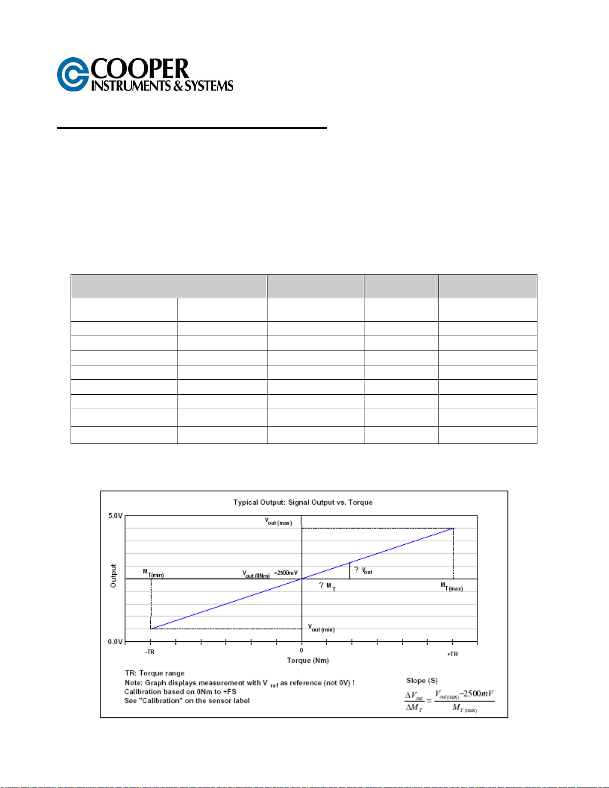
3.0 TYPICAL SENSOR OUTPUT
Max Rated Torque
[Nm (ft-lb)]
bidirectional (+/-)
2.5 (1.8)
5.0 (3.7)
7.5 (5.5)
17.5 (12.9)
75 (55.3)
175 (129)
250 (184.3)
500 (368.6)
Max Overload
[Nm (ft-lb)]
Ft-Lbs
5 (3.6) 5000 / 1000
10 (7.4) 5000 / 1000
15 (11) 5000 / 1000
35 (25.8) 5000 / 1000
150 (110.6) 5000 / 1000
350 (258) 5000 / 1000
350 (258) 5000 / 1000
750 (552.9) 5000 / 1000
Max Rotational
[rpm]
Round / Square
CF 59 1 V-11/18/02
Page 2
V
out(max)
between 0.5V and 4.5V; the actual signal output range depends on the calibraton value and the torque range.
and V
out(min)
are defined by the slope of each sensor. This means, the output is capable to be
LXT 971
(Round Shaft with
Keyway)
LXT 970
(Square Drive)
sFt
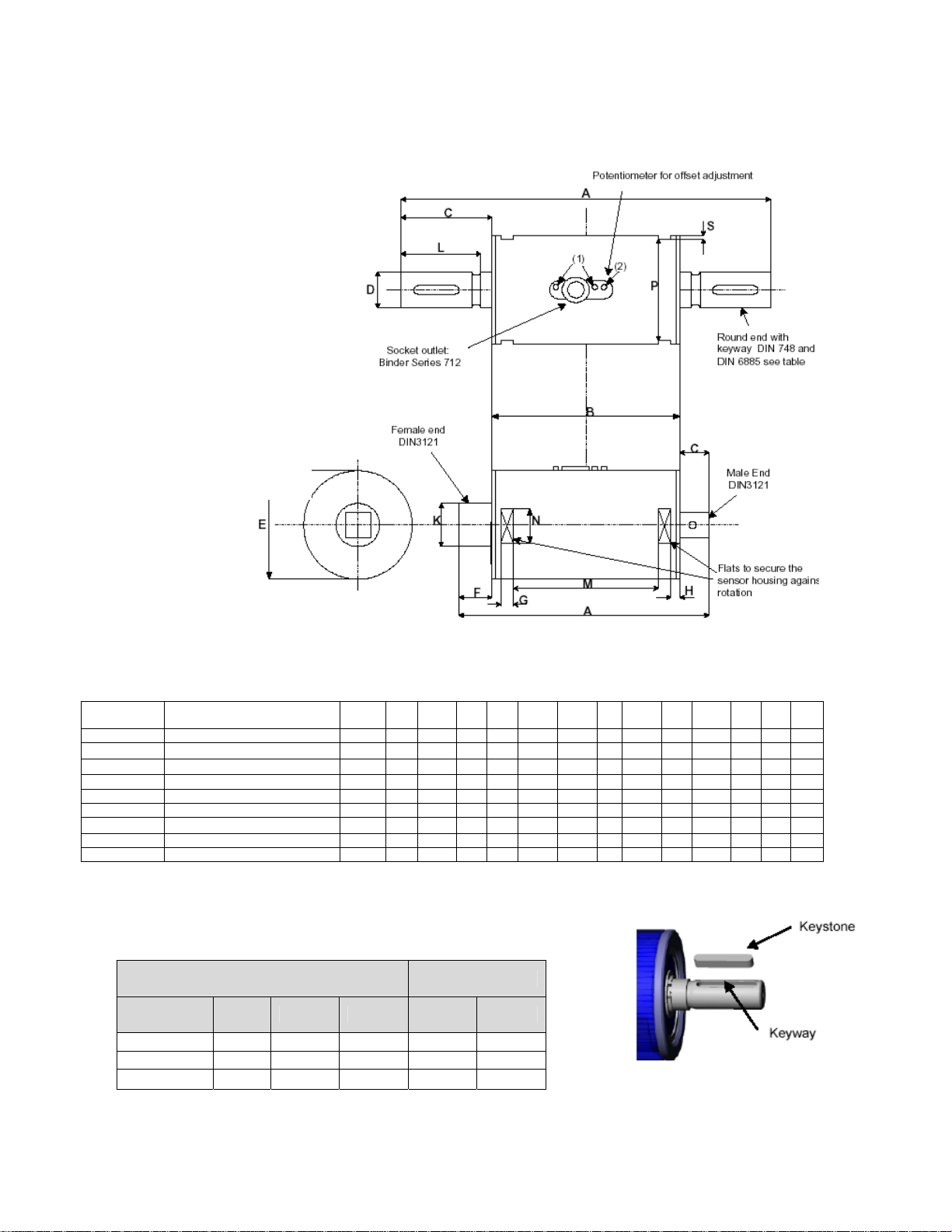
(1) Do not loosen or tighten the mounting screws.
(2) See 8.4 – Offset adjustment
Dimensions Nominal Torque Capacity
LXT 970
¼ inch
3/8 inch
½ inch 175-250 123.5 70 18.5 - 50 35 8 5 24 - 43.9 18 47 1.5
¾ inch 500 146 87 29.6 - 60 29.6 10.5 2 33.5 - 61.4 19 57 1.5
LXT 971
Ø 9 mm
Ø 14 mm 75 139 70 34.5 14 50 - 8 5 - 30 43.9 18 47 1.5
Ø 19 mm 175-250 179 70 54.5 19 50 - 8 5 - 50 43.9 18 47 1.5
[Nm]
2.5 - 5.0 - 7.5 - 17.5 95.5 70 9.5 - 40 16
75
2.5 - 5.0 - 7.5 - 17.5
A B C D E F G H K L M N P S
8 5 12 - 43.9 15 37 1.5
107 70 13 - 50 24 8 5 18 - 43.9 18 47 1.5
125 70 27.5 9 40 - 8 5 - 23 43.9 15 37 1.5
4.0 KEYWAY DIMENSIONS (ROUND SHAFT
SENSORS ONLY)
Dimensions Keyway [mm] Keystones
Shaft
Diameter
Width Depth Length Height Length
Ø 9 mm 3 1.8 18.5 3
Ø 14 mm 5 3 25.5 5
Ø 19 mm 6 3.5 45.5 6
18
25
45
CF 59 2 V-11/18/02
Page 3

5.0 TERMINAL DIAGRAM
Terminal diagram of socket-outlet: View looking at sensor socket.
Pin Color Description
1 White Supply Voltage Vcc
2 Brown Signal Output Vout
3 Black Ground
4 Blue (Not Used)
5 Grey Reference Voltage 2.5V
The output V
represents the virtual zero point for direct +/- torque
measurement (See below “Sensor cable and
connection” section B).
Use connector with proper shielding termination (360 deg). Otherwise maintain shield as close to cable
ends as possible and connect to earth ground.
Sensor Cable Connection
A) This circuit is recommended for absolute torque
measurement, e.g. 2.5V equals to approx. 0 Nm
Grey and blue wires are not in use.
is a constant 2.5V output and
ref
B) This circuit is recommended for relative torque
measurement, e.g. 0V equals to approx. 0 Nm
Blue wire is not in use.
6.0 OPERATING INSTRUCTIONS
6.1 Field of Application
The torque sensor is intended for use in an industrial environment (e.g. in test stands).
6.2 Scope of Delivery
The torque sensor set consists of the sensor unit (signal detector and signal conditioning electronics integrated
into sensor housing); one connecting cable (length 1.5 m) with soldered plug connector; and one installation and
instruction manual.
6.3 Sensor Installation and Removal
The shafts connected to the torque sensor must be properly aligned. A shaft coupling should be selected to
eliminate or minimize backlash, angular misalignment, end-float, or other mechanical situations that would affect
the performance or operation of the torque sensor. Secure the sensor utilizing the 8mm guides located on the
sensor body (optional sensor holder). A maximum cable length of 3 m must not be exceeded. Using a cable or
connector other than supplied by Cooper Instruments, or a cable supplied by Cooper that is of a different length
may affect the overall performance of the sensor. *Prior to removing the sensor from operation, remove all
lateral forces or torque stored in the mechanical assembly. Remove the keys from the shafts before loosening
the mounting screws. *
DO NOT REMOVE THE SHAFT WITH TORQUE APPLIED TO THE SENSOR.
CF 59 3 V-11/18/02
Page 4

6.4 Offset Adjustment
The sensor is preset at the factory to indicate an output signal at 0 Nm of 2.5 volts. The output voltage signal
can be adjusted via a potentiometer (2) (Refer to Section on Mechanical Dimensions). Remove the headless
screw; and using a plastic screwdriver, set the potentiometer to 2.5 V using a plastic screwdriver. Replace the
headless screw until flush with the surface of the housing.
Factory setting is 2.5V.
6.5 Interface Description
Mechanical Interface:
For transmission on both ends of the shafts are keyway adapter or square ends (male/female) available.
Electrical Interface:
On the sensor outside is a 5 pole plug for power supply and signal lines (see Terminal diagram).
6.6 Operation (Normal, Optimization)
For optimal measurement results, do not exceed the rated torque when using the sensor. Do not operate the
sensor at the maximum rotational speed for extended periods of time. Observe the prescribed operating
conditions to ensure trouble free and maintenance free operation of the sensor.
6.7 Operation Outside Specified Conditions, Corrective Action
External magnetic fields may have an adverse effect on the measurement results. Excessive mechanical stress
on the sensor (e. g. longitudinal forces / loads outside the specified limits, strong vibrations) may cause damage
to the sensor and thus lead to incorrect signal outputs. Should these conditions be experienced, readjusting the
sensor may improve the performance (see Section 7.4 - Offset Adjustment). If the problem persists, do not
open the sensor housing. Contact Cooper Instruments for assistance.
6.8 Commissioning
After sensor installation, observe the following procedure:
• Switch on the power supply unit and check the supply voltage. Peak voltages to the sensor must be avoided!
Be sure to verify the power supply voltage prior to connecting the sensor!
• Using the supplied sensor cable, connect the sensor to the power supply unit.
• Connect the sensor output to a high-resistance device such as an A/D converter, oscilloscope, PLC analog
board, PC measurement board, etc.
• With the sensor under no mechanical load (zero torque condition), determine the output signal voltage.
• If required: Adjust the signal output to read 2.5 V (0 Nm); see 7.4 - Offset Adjustment.
6.9 Service and Maintenance
There are no required maintenance operations for the sensor.
6.10 Disposal
Please return the device to the manufacturer for disposal.
6.11 Handling and Transportation
During sensor handling, storage and transportation, it is important to ensure that the sensor is not exposed to
any magnetic or electromagnetic fields higher than specified by the electromagnetic compatibility. Static or
dynamic loads on the sensor must be avoided.
6.12 Safety Precautions
1. Do not open the sensor housing under any circumstances.
2. Do not remove or loosen the locating rings on the shaft ends.
3. Do not loosen or tighten the nut of the flange-mounting socket-connector (1) (see Mechanical dimensions).
CF 59 4 V-11/18/02
Page 5

*Carrying out any of the above operations (1-3) results in loss of sensor calibration. The sensor does no
longer operate regularly and must be returned to Cooper for calibration and certification.
4. Use only power supplies that are properly isolated from the electrical mains.
5. Observe the specifications regarding maximum electrical and mechanical loads on the sensor, as shown on
the sensor label and in section 4 - Technical Features.
6. Protect the sensor from exposure to any electric or magnetic fields.
7.0 WARRANTY REPAIR POLICY
Limited Warranty On Products
Any Cooper Instruments product which, under normal operating conditions, proves defective in material or in
workmanship within one year of the date of shipment by Cooper will be repaired or replaced free of charge
provided that a return material authorization is obtained from Cooper and the defective product is sent,
transportation charges prepaid, with notice of the defect, and it is established that the product has been properly
installed, maintained, and operated within the limits of rated and normal usage. Replacement or repaired
product will be shipped F.O.B. from our plant. The terms of this warranty do not extend to any product or part
thereof which, under normal usage, has an inherently shorter useful life than one year. The replacement
warranty detailed here is the buyer’s exclusive remedy, and will satisfy all obligations of Cooper whether based
on contract, negligence, or otherwise. Cooper is not responsible for any incidental or consequential loss or
damage which might result from a failure of any and all other warranties, express or implied, including implied
warranty of merchantability or fitness for particular purpose. Any unauthorized disassembly or attempt to repair
voids this warranty.
Obtaining Service Under Warranty
Advance authorization is required prior to the return to Cooper Instruments. Before returning the item, contact
the Repair Department c/o Cooper Instruments at (540) 349-4746 for a Return Material Authorization number.
Shipment to Cooper shall be at buyer’s expense and repaired or replacement items will be shipped F.O.B. from
our plant in Warrenton, Virginia. Non-verified problems or defects may be subject to a $100 evaluation charge.
Please return the original calibration data with the unit.
Repair Warranty
All repairs of Cooper products are warranted for a period of 90 days from date of shipment. This warranty
applies only to those items that were found defective and repaired; it does not apply to products in which no
defect was found and returned as is or merely recalibrated. It may be possible for out-of-warranty products to
be returned to the exact original specifications or dimensions.
* Technical description of the defect: In order to properly repair a product, it is absolutely necessary for Cooper
to receive information specifying the reason the product is being returned. Specific test data, written
observations on the failure and the specific corrective action you require are needed.
CF 59 5 V-11/18/02
Page 6

8.0 TECHNICAL FEATURES
Description Symbol
LXT 970-971 Series
Unit Remarks
Torque Range
Maximum rated torque - bi-directional M 2.5 5.0 7.5 17.5 75 175 250 500
Analog signal output V
0.5 - 4.5 Vdc
out
Nm Full Scale = 0 to maximum rated torque
Degree of protection IP 50 Per EN60529
Supply voltage Vcc 9.0 .. 12.0 Vdc
Signal output at 0 Nm (adj. via offset Pot.) V
out (0)
2.5 V Adjustable via potentiometer
Signal output resistance 50 Ω
Signal band width BW 1000 Hz
RD=round shaft 0 ... 5000 (RD)
Rotational speed
SQ=square drive
n
0 ... 1000 (SQ)
Rpm
Repeatability < ±0.1 %FS DKD-R 3-5
Hysteresis and linearity failure and signal
variation during rotation
< 1 <2 % FS
Operating temperature range Top 0 ... +70 °C Reference temperature: 21°C
Maximum longitudinal force between shaft and
housing
40 N Influence on measurement signal <1%FS
F
l
Maximal lateral force Fq 50 N Influence on measurement signal <1%FS
Zero drift (temperature-related) < ±0.1 % FS / K
Resistance to magnetic fields (distance 70mm)
4000 Oe
318 kA/m
Minimal distance from sensor housing:
70mm
EN 55011, EN 6100-4-3,EN 6100-4-6, EN
Electromagnetic compatibility
6100-4-4, EN 6100-4-2, EN 50204, EN
50081-3, EN 50082-2
Not intended for medical use
Storage temperature T -20...+100 °C
Weight
Round 383 386 392 400 685 856 861 XX
Square 395 397 401 386 652 754 749 1385
g
CF 59 6 V-11/18/02
 Loading...