

Page 1

LTW 650
WEIGH MODULE KIT
USER’S GUIDE
www.cooperinstruments.com
PH: 540-349-4746 • FAX : 540-347-4755
Page 2

CONTENTS
1.0 INTRODUCTION ....................................................................................................................1
2.0 MECHANICAL INSTALLATION ............................................................................................1
2.1 General Installation Guidelines for Weigh Modules ....................................................................1
2.2 Installing the LTW 650 ....................................................................................................................2
3.0 LOAD CELL WIRING.............................................................................................................3
4.0 JUNCTION BOX CONNECTIONS, ADJUSTMENTS & CALIBRATION ...............................4
5.0 TROUBLESHOOTING ...........................................................................................................4
6.0 MAINTENANCE AND REPLACEMENT PARTS ...................................................................5
7.0 WARRANTY REPAIR POLICY ..............................................................................................7
CF24 ii 05/29/01 (V-6/99)
Page 3
1.0 INTRODUCTION
The LTW 650 Weigh module kit provides an extremely accurate
method for weighing medium and large capacity tanks, hoppers, bins,
and reactors. The design uses a double-ended shear beam load cell
and transmits the load through a clamping load plate to the center of
the load cell. This design is very effective in providing for thermal
Thermal
Expansion
expansion/confrontation with little friction.
In the majority of applications, the modules are self-checking and held
captive with no need for check or stay rods, making this mount a good
choice for areas with frequent seismic activity.
The LTW 650 is available in cast iron, mild steel, or stainless steel in sizes from 1,000-75,000 lb.
CAUTION! The installation should be planned by a qualified structural engineer. Each installation
is unique, and this manual is meant to serve only as a general guideline for installation.
2.0 MECHANICAL INSTALLATION
2.1 General Installation Guidelines for Weigh Modules
1. The mounting surface for the base and top plate must be level. After installation, the top and bottom plates
must be level within ±0.5°. If the mounting surfaces are not level, then shims and or grout may be used to level
the mount.
If possible, check that the module is level when the vessel is fully loaded because excessive deflections in legs
and supporting structures may cause additional side forces that greatly affect accuracy. Deflection of the
mount’s top or base plate due to loading should not exceed ±.5°. Reinforcement of legs or other support
structures may be necessary to correct this. Vessels with long legs should have cross bracing applied between
adjacent legs to keep them from spreading under load.
2. Compression mounting systems use three, four, or more mounts. More than eight-module systems should be
avoided as even weight distribution becomes extremely difficult to achieve. The load on each module should
vary by no more than 20%. During installation, add shims where necessary to achieve correct load distribution.
3. If the actual load cells are used during installation of the weigh
module, extreme care must be taken to prevent overload damage.
A tank or hopper weighing several tons can exert huge forces
when dropped only a fraction of an inch. Dummy load cells can be
used during installation.
4. It is crucial that all piping or conduit be horizontal and flexible. If
flexible piping is not used, make sure the distance from the vessel
to the first pipe support is 20-30 times the pipe diameter. In
smaller, lower capacity tanks and hoppers, isolating the resultant
forces becomes extremely critical.
LEVEL
+/- 0.5
FLEXIBLE PIPING
J-BOX
5. Load cells should not be installed in the modules until all welding is completed. The heat generated from
welding current passing through a load cell can damage the adhesive holding the strain gauge to the body. If
possible, use a dummy load cell when welding to maintain finished height. If welding is unavoidable after load
cell installation, connect the ground in such a way that the current does not flow through the load cell. For
example, if welding on the module top plate, the ground must be connected to the vessel, not to the mount
base or support structure. Also, protect the load cell and cable from weld splatter.
6. When possible, use only “hermetically sealed” load cells in washdown applications. Environmentally protected”
load cells are not suitable for such applications and will be damaged. If tanks and surrounding equipment are
CF24 1 05/29/01 (V-6/99)
Page 4

frequently steam cleaned or if the load cell is subjected to direct washdown, a protective shroud for the weigh
module is recommended. Proper drainage is necessary so the weighing assembly is not standing in water.
7. All support points should be equally stiff so that they deflect by the same amount as the vessel is loaded.
2.2 Installing the LTW 650
Load Plate and Clamp
Pin
Cotter Pin
Flat Washer
Load Cell
Lockwasher
Clamp Bolt
Tank Mount Base
1. The type of installation and strength of the mounting surface governs the method of locating, attaching, and
assembling the LTW 650 assembly. Carefully consider three areas that commonly cause accuracy problems:
• Are the supporting legs adequately braced so they will not spread when the system is fully loaded?
• Does the supporting structure have the necessary strength to prevent excessive deflection when the system
is fully loaded?
• Is there attached equipment such as skirting, venting, or piping which is likely to cause binding or lack of
flexibility?
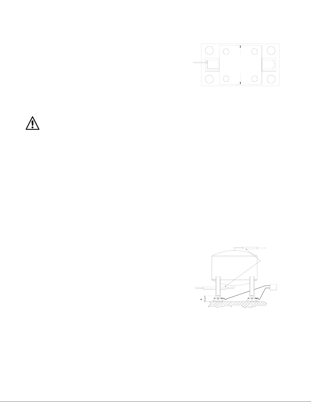
2. Determine where to position the module and in which direction it should be oriented. The LTW 650 is designed
to allow for lateral movement in the direction perpendicular to the longitudinal axis of the load cell. These weigh
modules should be oriented so that the movement due to the longitudinal axis. Sample mounting orientations
to accommodate expansion for different vessel shapes are as follows:
FIGURE 1
FIGURE 2
FIGURE 3
FIGURE 5
FIGURE 4
3. Assemble the modules by attaching the load cell to the load plate and clamp using the lockwashers and clamp
screws. Then, insert the load pins through the base plate and load cell. Secure the load pins with washers and
cotter pins.
Note: the arrow on the load cell should point in the direction of the load.
4. Lift and block the vessel to the same height as the assembled modules.
5. Remove the block from one support point and slide that module into position.
CF24 2 05/29/01 (V-6/99)
Page 5

6. As the module is being fitted under the leg of the vessel, verify that the leg’s center line passes through the
center of the load plate (through the center of the load cell).
7. Lower the corner or side of the vessel carefully onto the load plate.
CAUTION! Use extreme care when lowering the vessel. The force of a vessel weighing several
tons can damage a load cell if dropped only a fraction of an inch.
8. With the load plate positioned approximately level, mark holes for attaching the load plate to the vessel’s
9. Repeat steps 5-8 for the weigh modules at the remaining corners or sides.
10. Verify that there is no initial misalignment between the tank mount base and load plate and clamp and that the
11. Attach the base plates to the foundation using suitable anchors for concrete or by bolting or welding to a steel
12. Check that the top plates are no more than ±5° out of level. Shim if necessary and fully tighten mounting bolts.
13. IMPORTANT: Check that each pin of each module has approximately equal weight applied. If a pin is loose,
14. If dummy cells are used, replace with the load cells. Refer to step 3.
15. To achieve equal load distribution, final height adjustments can be made with shims between the load plate and
mounting surface. Make holes and attach the load plate loosely to vessel with suitable fasteners.
load plate and clamp is centered with respect to the load cell. Also, verify that the load cell, clamp, and load
cell assembly is centered in the base plate. Relocate if necessary.
structure or subplate. Verify that the base plates are no more than ±.5° out or level. Shim as necessary.
shim between the base plate and foundation as necessary.
clamp and the vessel. The variation in load among the cells should be no more than 20%. The load
distribution can be checked accurately by exciting each load cell in turn and measuring the output with a
voltmeter.
3.0 LOAD CELL WIRING
1. Route the load cell cables so they will not be damaged or cut. Cable should not be routed near heat sources
greater than 150°F. Do not shorten any load cell cable. The load cell is temperature compensated with the
supplied length of cable. Cutting the cable will affect temperature compensation. Coil and protect excess cable
so it will not be mechanically damaged or be sitting water.
2. Provide a drip loop in all cables so that water or other liquids will not run directly down the cables onto either
the load cells or the junction box. Attach load cell cable to the dead structure, not the vessel.
3. If conduit protection is necessary against mechanical or rodent damage to the load cell cables, use flexible
conduit and conduit adapters at the load cells.
4. Connect cables for standard Stainless Steel load cells to the summing board in the junction box according to
the guide shown below and the labels on the terminal strips of the junction box. To verify the wiring scheme,
see the certification shipped with each load cell.
5. For better performance, use positive and negative remote sense lines if the wiring running from the junction box
to the indicator is longer than 25 feet.
CF24 3 05/29/01 (V-6/99)
Page 6

DRIP
LOOP
LOAD CELL WIRE COLOR FUNCTION
Red +EXC
Black -EXC
Green +SIG
White -SIG
Gray or Bare SHIELD
4.0 JUNCTION BOX CONNECTIONS, ADJUSTMENTS & CALIBRATION
1. Refer to the Junction Box manual for trimming details.
2. Refer to the indicator manual for system calibration details.
5.0 TROUBLESHOOTING
If the system powers up and gives some type of stable digital readout that varies with the load on the system, any
system problems are probably caused by factors other than the load cells. The load clls are often blamed for
malfunctioning systems, but 90% of the time, the problem lies elsewhere. Look for mechanical causes for your
problem first.
If the system can be calibrated but doesn’t return to zero, loses calibration, or demonstrates non-linearity or nonrepeatability, see the following chart for possible causes and do the following checks.
Symptom Possible Cause
No return to zero
Non-linearity
Non-repeatability
Lost calibration Out of level or plumb; moisture problem mechanical binding
Drifting readout Moisture in junction, cables, or load cell; mechanical binding
1. Check weigh module for debris restricting load cell movement or debris between scale and structure.
2. Check that tank/vessel and modules are plumb, level, and square at the critical areas.
3. Check all piping and conduit for connections, which restrict vessel movement.
4. If check rods are used, loosen all connections to finger tight only for testing.
Mechanical binding or debris in seals or under load cells; may
have lost system calibration
Thermal expansion or deflection under load causing binding or
side load
Loose load cell mount; drifting caused by moisture, load cell
overload or shock damage; mechanical binding
CF24 4 05/29/01 (V-6/99)
Page 7

5. Check load cell cables for physical or water damage.
6. Check all electrical connections, especially in the junction box.
If the problem still is not found:
7. Check possible indicator malfunction by using a load cell simulator to input a known good signal into the
indicator.
8. Disconnect each load cell’s signal leads at the junction box and check individual load cell outputs with a
multimeter. Then check input/output impedances for comparison with load cell manufacturer’s specifications.
If after all these checks the problem still cannot be isolated, reconnect all but one load cell. Replace the load cell
with a load cell simulator. If there is a problem with a particular load cell, the symptom should disappear when that
load cell is disconnected and replaced with the simulator.
6.0 MAINTENANCE AND REPLACEMENT PARTS
4
6
3
8
2
5
1
7
LTW 650 CAST IRON MODULES
No. Description Reqd.
1 Weigh Module Base 1 18439 18441
2 Washer 4 15165 15179
3 Load Plate and Clamp 1 18443 18445
4 Cotter Pin 1/8” x 3/4 ”/1/8” x 1” 4 15232 15237
5 Pin 2 18449 18448
6 Lock Washer 2 15167 15181
7 Clamp Bolt 2 15080 15099
8 Load Cell See Load Cell Product Selection Guide
*A-size mounts use load cells with capacities from 1,000-5,000 lb.
*B-size mounts use load cells with capacities from 10,000-25,000 lb.
Replacement Part Numbers
A* B*
CF24 5 05/29/01 (V-6/99)
Page 8

4
3
8
2
5
1
6
7
LTW 650 MILD STEEL MODULES
No. Description Reqd.
1 Weigh Module Base 1 22745 22748 22751 22751
2 Washer 4 15165 15179 15188 15188
3 Load Plate and Clamp 1 22746 22749 22752 25364
4 Cotter Pin 4 15232 15237 15237 15237
5 Pin 2 22747 22750 22753 22753
6 Lock Washer 2 15167 15181 15189 15189
7 Clamp Bolt 2 14757 15097 14799 14799
8 Load Cell See Load Cell Product Selection Guide
A* B* C* D*
*A-size modules use load cells with capacities from 1,000-5,000 lb.
*B-size modules use load cells with capacities from 10,000-25,000 lb.
*C-size modules use load cells with a capacity of 50,000-75,000 lb.
*D-size modules use load cells with a capacity of 75,000 lb.
Replacement Part Numbers
LTW 650 STAINLESS STEEL MODULES
No. Description Reqd.
1 Weigh Module Base 1 22754 22756 10124 10124
2 Washer 4 15166 15180 15188 15188
3 Load Plate and Clamp 1 22755 22757 10128 25365
4 Cotter Pin 4 15233 15238 15258 15258
5 Pin 2 22747 22750 22753 22753
6 Lock Washer 2 15168 15182 15189 15189
7 Clamp Bolt 2 14758 15098 14800 14800
8 Load Cell See Load Cell Product Selection Guide
A* B* C* D*
*A-size modules use load cells with capacities from 1,000-5,000 lb.
*B-size modules use load cells with capacities from 10,000-25,000 lb.
*C-size modules use load cells with a capacity of 50,000-75,000 lb.
*D-size modules use load cells with a capacity of 75,000 lb.
Replacement Part Numbers
CF24 6 05/29/01 (V-6/99)
Page 9

7.0 WARRANTY REPAIR POLICY
Limited Warranty On Products
Any Cooper Instruments product which, under normal operating conditions, proves defective in material or in
workmanship within one year of the date of shipment by Cooper will be repaired or replaced free of charge provided
that a return material authorization is obtained from Cooper and the defective product is sent, transportation
charges prepaid, with notice of the defect, and it is established that the product has been properly installed,
maintained, and operated within the limits of rated and normal usage. Replacement or repaired product will be
shipped F.O.B. from our plant. The terms of this warranty do not extend to any product or part thereof which, under
normal usage, has an inherently shorter useful life than one year. The replacement warranty detailed here is the
buyer’s exclusive remedy, and will satisfy all obligations of Cooper whether based on contract, negligence, or
otherwise. Cooper is not responsible for any incidental or consequential loss or damage which might result from a
failure of any and all other warranties, express or implied, including implied warranty of merchantability or fitness for
particular purpose. Any unauthorized disassembly or attempt to repair voids this warranty.
Obtaining Service Under Warranty
Advance authorization is required prior to the return to Cooper Instruments. Before returning the item, contact the
Repair Department c/o Cooper Instruments at (540) 349-4746 for a Return Material Authorization number.
Shipment to Cooper shall be at buyer’s expense and repaired or replacement items will be shipped F.O.B. from our
plant in Warrenton, Virginia. Non-verified problems or defects may be subject to a $100 evaluation charge. Please
return the original calibration data with the unit.
Repair Warranty
All repairs of Cooper products are warranted for a period of 90 days from date of shipment. This warranty applies
only to those items that were found defective and repaired; it does not apply to products in which no defect was
found and returned as is or merely recalibrated. It may be possible for out-of-warranty products to be returned to
the exact original specifications or dimensions.
* Technical description of the defect: In order to properly repair a product, it is absolutely necessary for Cooper to
receive information specifying the reason the product is being returned. Specific test data, written observations on
the failure and the specific corrective action you require are needed.
CF24 7 05/29/01 (V-6/99)
 Loading...