

Page 1

LTL 720
Dyna Link Tension
Load Sensor
User’s Guide
Page 2

www.cooperinstruments.com
PH: 540-349-4746 • FAX: 540-347-4755
Page 3

CONTENTS
INTRODUCTION ..........................................................................................................................1
UNPACKING................................................................................................................................1
INSTALLATION ...........................................................................................................................1
BATTERIES .................................................................................................................................1
OPERATION ................................................................................................................................2
DIGITAL DISPLAY.......................................................................................................................2
POWER SWITCH .........................................................................................................................2
ZERO SWITCH.............................................................................................................................2
PEAK............................................................................................................................................3
SET POINTS ................................................................................................................................3
To Enable SET-POINTS ........................................................................................................................3
SET-POINT Examples ........................................................................................................................... 4
To Disable a SET-POINT....................................................................................................................... 4
UNIT(S) ........................................................................................................................................4
SETUP/CAL .................................................................................................................................5
CLEAR/CANCEL .........................................................................................................................5
END ..............................................................................................................................................5
CALIBRATION UNIT(S)...............................................................................................................5
CALIBRATION.............................................................................................................................6
RCAL (OPTIONAL)......................................................................................................................6
TO CALIBRATE USING RCAL....................................................................................................7
FINE CALIBRATION....................................................................................................................8
AUTOMATIC POWER OFF (“AOFF”).........................................................................................8
AUTOMATIC ZERO TRACKING (“AZT”) ...................................................................................8
ERROR CODES ...........................................................................................................................9
RS232 (EIA232D) SERIAL OUTPUT ...........................................................................................9
ANALOG OUTPUT (OPTION) ...................................................................................................10
SPECIFICATIONS......................................................................................................................11
OPTIONS & ACCESSORIES.....................................................................................................11
SERVICE INITIALIZATION PROCEDURE ................................................................................12
INITIAL CAL...............................................................................................................................12
PROPER LOADING PROCEDURE ...........................................................................................14
WARRANTY REPAIR POLICY..................................................................................................14
Limited Warranty On Products .......................................................................................................... 14
Obtaining Service Under Warranty....................................................................................................15
Repair Warranty ..................................................................................................................................15
CF 33 ii 8/5/00 Rev.0
Page 4

INTRODUCTION
The LTL Dyna-Link Tension Load Sensor represents advancement over earlier electronic attempts to replace
mechanical Dynamometers. The Series 720 Dyna-Link models offer standard features not found on mechanical
dynamometers.
Standard Features:
• Rugged construction
• Very long battery life. 500 hours on two standard “C” cells
• All functions and units are clearly annunciated on the Liquid Crystal Display. Digits are 1” high for easy distant
viewing
• Two user programmable Set Points can be used for safety and warning applications or for limit weighing. An
optional relay unit is available for interfacing the Dyna-Link to sirens, strobes, motors, etc.
• All commonly used internationally recognized units are available: pounds (lb), kilograms (kg), Short Tons (t),
Metric tons and dekaNewtons (daN)
• Digital calibration for easy maintenance
• Available with standard and remote displays
• Memory backup for Calibration, Setup parameters, and Set-Points
• The remote display version is available with optional RS232 output for printer or computer interfacing
UNPACKING
On receipt, be sure all parts ordered are included. A standard system will include the following:
Standard Dyna-Link Systems
1. 1 ea. LTL-720 Dyna-Link indicator
2. 2 ea. “C” cell alkaline batteries
3. 2 shackles (Optional)
4. Carrying Case (Optional)
Remote Dyna-Link Systems
1. 1 ea. LTL-720 load cell with pendant cable (typically 25’)
2. 1 ea. LTL-720 remote hand-held indicator (single and dual display)
3. 2 ea. “C” cell alkaline batteries
4. 2 shackles (Optional)
5. Carrying Case (Optional)
INSTALLATION
The Dyna-Link can be installed into a variety of applications. Its primary application is measuring tension in load
monitoring and certification applications.
WARNING: Due to the lack of any swivel fittings, it is important that all torque loads are kept to a minimum. The
use of properly rated fittings is imperative for safety and performance. The LTL-720 Dyna-Link are sized for
industry-standard shackles.
BATTERIES
A low battery lamp will appear when the expected life is approximately 60 hours. At approximately 10 hours
remaining, the lamp will start to blink. If the power is to low, the unit will automatically power down.
To Remove/Replace the Batteries
1. Remove the yellow battery cap in the load cell body.
2. Remove the batteries by tilting the load cell body slightly.
3. Replace the batteries with 2 fresh alkaline “C” cells, positive end first.
CF 33 1 8/5/00 Rev.0
Page 5
4. Replace the battery cap. Ensure that the yellow cap is screwed in all the way to maintain sealing.
Note: The O-ring should be lubricated with O-ring lubricant periodically.
OPERATION
The Dyna-Link operates in two modes:
1. Gross Tension mode measures the current tension on the Link.
2. Peak Tension stores the highest reading the Link has measured. The display is only updated when a higher
value is measured.
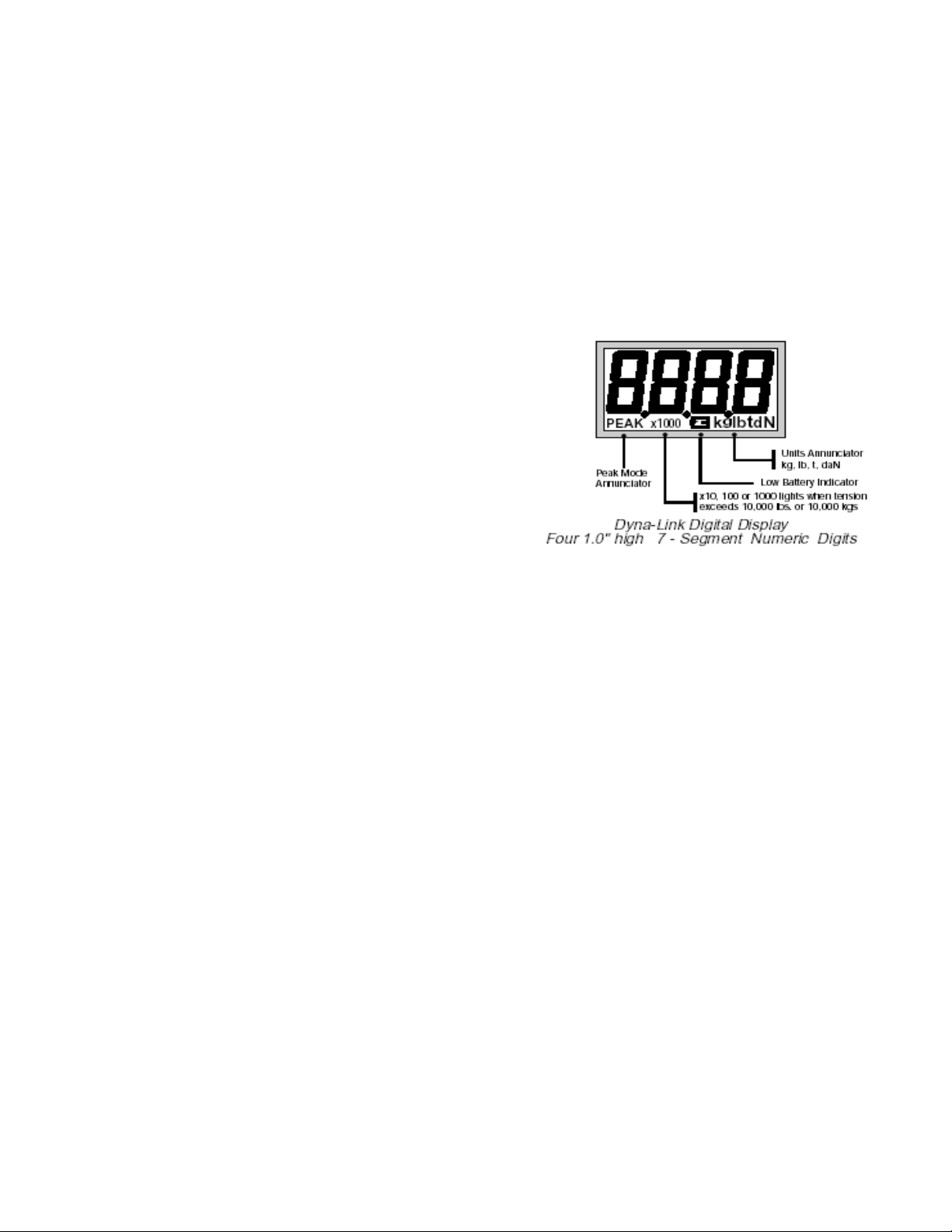
DIGITAL DISPLAY
The Dyna-Link Liquid Crystal Display (LCD) is used for tension
indications as well as setup and error messages. During tension
measurement, the digits can indicate a maximum of four digits of
tension. When the reading exceeds four digits the”x1000”
annunciator and decimal point will light indicating that the
readings should be multiplied by 1000. This “auto-ranging”
takes place in higher capacity Dyna-Links, 10000 lbs, kgs, or
daNs and up. The LCD has annunciators for the Peak Mode,
Low Battery, and Units.
POWER SWITCH
Function:
Turns the unit On and Off.
Action:
1. Push POWER
2. Display Check: All segments and LED’s are illuminated for 1 second.
3. The LCD displays the software version number for 1 second.
Final:
The unit reads the current tension in the last set mode – Gross Tension or Peak Tension.
ZERO SWITCH
Function:
Sets the Zero reading of the Dyna-Link.
Rules for Use:
1. The Dyna-Link must be stable within 2 display counts. If the reading is not stable, the zero button will not
function.
2. The Dyna-Link will accept a zero setting up to full capacity. Zero settings will subtract from the overall capacity
of the Dyna-Link. For example, if you zero out 1000 lbs on a 5000 lb Dyna-Link, the overall capacity will be
reduced to 4000 lbs (plus the allowed over-range amount – usually 9 divisions).
Action:
Push ZERO to zero the reading.
Final:
The digits display “0” (or 0.0, 0.00, or 0.000 depending on the resolution).
CF 33 2 8/5/00 Rev.0
Page 6

PEAK
Function:
Toggles between the Peak Tension and the Gross Tension modes.
Action:
1. Push PEAK
2. Display annunciator “PEAK” lights indicating Peak Tension mode. The “NEW PEAK” LED flashes while new
peak values are being recorded.
3. The last stored peak reading is displayed.
Final:
The LCD digits update only when a higher peak reading is obtained when a new higher reading is obtained, the
“NEW PEAK”LED will flash four times.
To Clear the Peak
Action:
While in the Peak Hold Tension mode, push ZERO.
Final:
The old Peak value is cleared; the digits display the current gross tension as a new peak. The “NEW PEAK”LED
flashes to indicate a new peak being stored.
To Turn Off the Peak Mode
Action:
Push PEAK. The “PEAK” annunciator will go out.
Final:
The previous peak reading is retained even in the normal reading mode and power off modes. The last stored
peak reading will be lost if the batteries are removed.
SET POINTS
The Dyna-Link is equipped with the capability of storing two Set Points. When the tension falls above or below
(depending on setting) the Set-Point value, the Dyna-Link responds by blinking an LED and by turning on a logic
output. This output can be used to interface to relays, lights, sirens, etc. (Contact Cooper for more details). Typical
uses for the Set Points include overload warnings, limit checking, and check weighing. Cooper provides an
optional relay interface box – AC power supply for easy Set-Point interfacing. During Set-Point entry the POWER
key will operate as an ENTER key, the ZERO key will operate as the DOWN selection key, the PEAK key will
operate as the UP selection key and CLEAR/CANCEL is initiated by pushing the ZERO and PEAK keys at the
same time (the SETUP/CAL key in the rear panel also functions as CLEAR/CANCEL).
Remote Units Only: The “*” key functions as the CLEAR/CANCEL key during all Set-Point and Setup functions.
The two Set-Points are designated SP1 and SP2 (the digit 5 is used to resemble an ‘S’).
To Enable SET-POINTS
1. Turn the Dyna-Link off.]
2. Hold down the PEAK key and turn the Dyna-Link on. After 1 second let up on the PEAK key.
3. The display will read “Unit”. Push UP (PEAK) or DOWN (ZERO) to select Set-Point 1 (“SP1”) or Set-Point 2
(“SP2”).
4. Push ENTER (POWER). You are now in the Set-Point Mode entry menu.
5. The display will start to flash the current Set-Point Mode of either “HI”,”LO”, or “OFF”. Push the UP or DOWN
key to change the mode. Low (LO) will trigger an alarm if the tension falls below the entered Set-Point value.
High (HI) will trigger if the tension rises above the entered Set-Point value. A third choice of “OFF” is used to
disable the Set-point.
6. Push ENTER (POWER) to set the Set-Point Mode.
CF 33 3 8/5/00 Rev.0
Page 7

7. You are now in the numeric entry portion of the Set-Point procedure. The left-most digit flashes. Push the UP
(PEAK) or DOWN (ZERO) key until the first digit of the desired Set-Point value is displayed. Push ENTER
(POWER). The CLEAR/CANCEL function can be used to change an entry if needed.
Note: To enter for example, 50 lbs on a 2000 lb Dyna-Link, the first two digits should be entered as zeros (0050).
1. The next digit flashes. Use UP, DOWN, and ENTER keys to finish out the desired Set-Point value.
2. You are now back in the Set-Point Menu. Push UP or DOWN until the display reads “End” and push ENTER
(POWER) to return to normal operation or use the UP/DOWN keys to select the other Set-Point for
modification.
Note: Set-Points are stored permanently in EEROM memory. Values are not lost when the batteries are drained or
removed.
SET-POINT Examples
Examples shown are for a 100000 lb Dyna-Link.
Example 1
Provides a warning when overload is close, and an additional second warning when overload is reached.
SP1 = 9000, sense HI
SP2 = 10000, sense HI
Example 2
For in limit indication. When both Set-Points are on, the tension is between 5000 and 5050 lbs.
SP1 = 5000, sense HI
Sp2 = 5050, sense LO
With the optional relay box, the outputs could be combined for a single in-limits indication.
Example 3
For an out of limit indication. When either Set-Point is on the tension is outside the range of 2000 to 2500 lbs.
SP1 = 2000, sense LO
SP2 = 2500, sense HI
To Disable a SET-POINT
1. Turn the Dyna-Link off.
2. Hold down the PEAK key and turn the Dyna-Link on. After 1 second release the PEAK key.
3. The display will read “Unit”. Push UP (PEAK) or DOWN (ZERO) to select the Set-Point (SP1 or SP2) to be
disabled.
4. Push ENTER (POWER).
5. Use the UP/DOWN keys to select “OFF”. Push ENTER (POWER).
6. You are now back in the Set-Point Menu. Select “End” and push “ENTER” to return to normal Dyna-Link
operation or select the other Set-point for additional modification as needed. (CLEAR/CANCEL will also return
the unit to normal operation).
UNIT(S)
Units can be changed from the front panel with the following procedure. Once the units menu is enabled, units are
changed by scrolling through the choices with the UP (PEAK) key or DOWN (ZERO) key and pushing ENTER
(POWER) when the desired unit is displayed. Available units are:1 lb (pounds), kg (kilograms), t (short tons), daN
(dekaNewtons), and kg X1000 (equivalent to Metric tons).
To change the units
1. Turn off the power. While holding down the “PEAK” key, turn the power back on. After 1 second release the
“PEAK” key.
2. The display reads “Unit” (if not push the UP or DOWN key to select the Unit mode).
3. Push ENTER (POWER). You are now in the units menu and the current units will be flashing.
CF 33 4 8/5/00 Rev.0
Page 8

4. Push UP/DOWN until the desired units are displayed, then push ENTER (POWER).
5. Now you are back in the front panel Setup Menu. To go back to normal operation, push CLEAR/CANCEL
(ZERO and PEAK pushed simultaneously or “*” key on Remote units) or scroll to the “End” message and push
“ENTER”.
SETUP/CAL
Function:
Allows front panel entry of seldom set parameters and initiates Calibration. SETUP/CAL is invoked by pushing the
key through the access hole in the back plate of the Dyna-Link (Remote units only: the SETUP/CAL key is located
on the front board inside the remote hand-held housing). For most of the setup functions the Dyna-Link’s keys will
work differently until SETUP/CAL is excited. The POWER key will operate as an ENTER (POWER) key, the ZERO
key will operate as the DOWN Selection Key, the PEAK key will operate as the UP Selection Key and the
SETUP/CAL key will be used as a CLEAR/CANCEL key. CLEAR/CANCEL can also be initiated via the front keys
by pushing ZERO and PEAK at the same time.
Remote units only: The “*” key functions as the CLEAR/CANCEL key during all Set-Point and Setup functions.
General setup procedure
1. a) Standard Dyna-Links Remove the seal screw in the back of the Dyna-Link. Push the SETUP/CAL switch
found inside the hole. A long thin insulated screwdriver or wood “Q-tip” stick is a good tool for this purpose.
The Dyna-Link will display “Unit”.
b) Remote Dyna-Links Turn the power off. Remove the batteries from the Dyna-Link. Remove the four hex
head screws holding the faceplate to the yellow handle enclosure. Carefully lift out the electronics/faceplate
assembly. After ensuring that the electronics package is not shorting against the case or any other metallic
surface, replace the batteries and turn the power back on. Push the SETUP/CAL switch (SW4) located on the
lower board and proceed as below. When the setup parameters you desire are entered, reassemble the unit
with the batteries out.
2. Options are viewed by repeated pushes of the UP or DOWN keys.
3. To change a parameter or initiate Calibration, push the ENTER (POWER) key. Selections are stored with the
ENTER (POWER) key.
4. Selecting CLEAR/CANCEL in most cases will cancel the current operation (and not save any changes to that
function). It is also used to clear digits or values during numeric entry. CLEAR/CANCEL can be used to exit
Setup altogether and return to normal operation.
5. In general, when the display is flashing, you are being prompted to use the ENTER (POWER) key to finish an
operation, or to use the UP or DOWN key to select a different option.
CLEAR/CANCEL
CLEAR/CANCEL is initiated by pushing both the ZERO key and the PEAK key simultaneously (Remote units can
use the “*” key as a Clear/Cancel key). Alternately push the SETUP/CAL key through the hole in the rear panel.
END
To exit from the Setup menu push CLEAR/CANCEL or scroll to the “End” message and push ENTER (POWER).
CALIBRATION UNIT(S)
Calibration units can be changed by scrolling through the choices with the UP (PEAK) key or DOWN (ZERO) key
and pushing ENTER (POWER) when the desired unit is displayed. Available units are: lb (pounds), kg (kilograms),
t (short tons), daN (dekaNewtons), and kg X1000 (equivalent to Metric tons).
CF 33 5 8/5/00 Rev.0
Page 9

To change the calibration units
1. Push “SETUP/CAL”. See “General Setup Procedure”.
2. The display reads “Unit” (if not, push the UP or DOWN key to select the Unit mode).
3. Push ENTER (POWER). You are now in the unit’s menu and the current units will be flashing.
4. Push UP/DOWN until the desired units are displayed, then push ENTER (POWER).
5. Now you are back in the Setup Menu. To go back to normal operation, push CLEAR/CANCEL (ZERO and
PEAK pushed simultaneously or rear panel SETUP/CAL). Push the UP/DOWN keys to select other setup
functions, or scroll UP/DOWN to END and press ENTER.
CALIBRATION
To calibrate a Dyna-Link, the user is required to have an accurate test weight system of adequate capacity.
To calibrate
1. Enable the Setup/Cal mode (See “General Setup Procedure”).
2. Ensure the proper units that you wish to calibrate in are selected (See “Calibration Units”).
3. Push UP/DOWN until the display reads “CAL”.
4. Push ENTER (POWER). You are now in the CAL menu.
5. The display will flash “ZEro” for 2 seconds as a prompt to unload the Dyna-Link for zeroing. (The number “2” is
used to resemble a “Z”)
6. The display will blink while showing the current zero value. When the zero display is stable, push “ZERO”.
7. The display will flash “LOAD” as a prompt to load the Dyna-Link with the calibration weight. A weight of at least
20% of capacity is required.
Note: A test weight of 50% or more of capacity is recommended for increased accuracy.
1. The capacity of the Dyna-Link will be displayed next as a default setting for the calibration weight.
2. The left-most digit will flash. Push the UP/DOWN keys until the first digit matches the applied calibration weight
first digit value. Push ENTER (POWER). At any time during the value entry, the CLEAR/CANCEL function can
be used to correct entries.
Note: For example, to enter 500 kg on a 1000 kg Dyna-Link, enter the first digit as a zero (0500).
1. The next digit will now flash. Using the UP/DOWN keys and the ENTER (POWER) key finish out the value
entry. Before the last digit is entered make sure that the calibration weight has stabilized, as this can affect
calibration accuracy. If there is not enough tension on the Dyna-Link, the Error Message “CErr” will show for 1
second and you must start over again with step 5. Again you must have at least 20% of capacity as a
calibration weight.
2. If calibration was successful, you will be returned to the SETUP menu ready to change another parameter if
desired. If finished push CLEAR/CANCEL to return to normal operation.
Note: After a standard calibration a new RCAL value should be stored. (See “To Store the RCAL Value”.)
RCAL (OPTIONAL)
RCAL is a useful indicator of Dyna-Links accuracy. If the RCAL value has not changed, the DynaLink accuracy is assured. A variation of a few counts is insignificant, but large variations between
displayed and stored RCAL values can indicate a problem.
Remote Unit RCAL
For users of the Remote Dyna-Link, the RCAL function is not automatic. The RCAL switch is on the small PCB
found in the load cell Link. This switch is accessed through the back panel of the load cell by removing the seal
screw and depressing the switch inside the hole. A long thin, insulated screwdriver or wood “Q-tip” stick is a tool for
this purpose.
To View an RCAL Value (Standard Dyna-Link)
CF 33 6 8/5/00 Rev.0
Page 10

The following procedure should be followed after a calibration:
1. Unload the Dyna-Link. Minimal weights left on the unit are acceptable. Wait for the digital readout to stabilize.
2. Push POWER to turn off the Dyna-link. While holding the zero key down, push the POWER key. The ZERO
key needs to be held down only about 1 second after the unit powers up. Release the ZERO key.
3. After the Power up sequence the display will show “RCAL” for one second then will flash the currently detected
RCAL value. Push ENTER (POWER). The value will be stored and normal Dyna-Link operation will continue.
4. Push ENTER (POWER). The value will be stored and normal Dyna-Link operation will continue.
Note: The only time the RCAL value can be stored is directly after calibration.
To Store a New RCAL Value (Remote Dyna-Link)
The following procedure should be followed after a calibration:
1. Unload the Dyna-Link. Minimal weights left on the unit are acceptable. Wait for the digital readout to stabilize.
2. Push POWER to turn off the unit. While holding the ZERO key down, push the POWER key. The ZERO key
needs to be held down only about 1 second after the unit powers up. Release the ZERO key.
3. After the Power up sequence, and the display is at zero, the display will show “RCAL” for one second then flash
the current zero value.
4. Hold down the RCAL switch (in Load Cell) until the value displayed stabilizes. Push ENTER (POWER). (It
may take two people to accomplish this if the load cell is not adjacent to the remote unit). The value will be
stored and normal Dyna-Link operation will continue when the RCAL switch is released.
Note: The only time the RCAL value can be stored is directly after calibration.
TO CALIBRATE USING RCAL
The following procedure is used in situations where Calibration weights are not available. Full accuracy of the
system is not assured but will typically be no worse than twice the standard accuracy.
Remote 1 Users: Remove the electric assembly from the hand-held enclosure before starting this procedure. (See
“General Setup Procedure” for removal).
1. Push POWER to turn off the Dyna-Link. While holding the ZERO key down, push the POWER key. The ZERO
key should be held at least one second after the unit powers up. Release the ZERO key.
2. After the Power-up sequence the display will show “RCAL” for one second then will blink the currently detected
RCAL value.
3. Make a note of the value and compare it to the value stored in memory (which will appear in step 12).
Remote 1 Units Only: The RCAL switch in the Load Cell must be pushed to observe the RCAL value.
4. Push ENTER (POWER) to exit this mode and continue normal Dyna-Link operation.
5. Without turning the power off, push the SELECT/CAL key (See “General setup procedure”).
6. Ensure the proper units that you wish to calibrate in are selected (See “Units” above).
7. Push UP/DOWN until the display reads “CAL”.
8. Push ENTER (POWER). You are now in the CAL menu.
9. The display will flash “ZEro” for two seconds as a prompt to unload the Dyna-Link for zeroing. (The number “2”
is used to resemble a “Z”)
10. The display will blink while showing the current zero value. When the zero reading is stable, push “ZERO”.
11. The display will flash “LOAd”. The RCAL will substitute for calibration weights at this point.
12. The stored RCAL value will now be displayed. If the value matches the previously noted value, there is no
need to recalibrate. Push CLEAR/CANCEL to exit RCAL. If the numbers do not match, go to step 13.
13. The far left digit will flash. Push the UP/DOWN keys until the first digit matches the noted RCAL first digit
value. Push ENTER (POWER). At any time during the value entry, the CLEAR/CANCEL function can be used
to correct entries.
14. The next digit will now flash. Using the UP/DOWN keys and the ENTER (POWER) key finish out the value
entry.
CF 33 7 8/5/00 Rev.0
Page 11

Remote 1 Units Only: Before pushing the final ENTER key, the RCAL switch in the load Cell must be pressed for
at least ten seconds before the last ENTER key is pressed and must be held down while the ENTER key is being
pressed.
15. If Calibration was successful you will be returned to the SETUP menu ready to change another parameter if
desired. If finished, push CLEAR/CANCEL to return to normal operation.
FINE CALIBRATION
Fine calibration is for minor adjustments to the calibration and is usually not necessary for accurate Dyna-Link
calibration. It is especially useful with hydraulic calibration fixtures for fine adjustments. For fine calibration, the
Dyna-Link should be zeroed before starting this procedure.
To Fine Calibrate
1. Push SETUP/CAL (unless you are already in the Setup Menu).
2. Push UP/DOWN until the display reads “FCAL”.
3. Push ENTER (POWER). You are now in the FCAL menu.
4. Apply a calibration weight of at least 50% of capacity.
5. The display will read the current gross weight if it is over 50% of capacity otherwise it will read “---“ and cannot
be adjusted.
6. Use the DOWN (ZERO) key to cause the displayed weight to move down slightly. Use the UP (PEAK) key to
cause the reading to move up. Each push of these two keys causes the calibration to shift by ¼-displayed
count. When the reading is acceptable (or you want to exit) push ENTER (POWER).
7. Now you are back in the Setup Menu. Push CLEAR/CANCEL to return to normal operation. (See “To Store a
new RCAL”).
AUTOMATIC POWER OFF (“AOFF”)
The Automatic Power Off feature, when enabled, prolongs the battery life of the Dyna-Link by turning the power off
at ten minutes of non-use. Any time a key is pressed, or the detected tension is in motion (tension changing by
more than two display counts), the ten-minute limit is reset. Therefore, the Dyna-Link will stay on indefinitely if the
tension is changing or any key is pressed at least once every ten minutes. The default factory setting is the Power
Off enabled mode. When disabled, the unit will stay on; only the power key will turn it off. It is recommended in
systems where the Set-Points are used for safety warnings, that the Automatic Power Off feature is disabled.
To Enable or Disable Automatic Power Off
1. Push SETUP/CAL.
2. Push the UP (PEAK) or DOWN (ZERO) key to scroll to the menu function “AOFF”.
3. Push ENTER (POWER). You are now in the Auto Off menu and the current selection will be flashing (either
“On” or “OFF”).
4. To disable Automatic Power Off (unit will turn off automatically after ten minutes of non-use), use the UP
(PEAK) key to scroll to “On”
5. To enable Automatic Power Off (unit will turn off automatically after ten minutes of non-use), use the UP
(PEAK) key to scroll to “On”.
6. Push ENTER (POWER). Now you are back in the Setup Menu. Push CLEAR/CANCEL to return to normal
operation.
AUTOMATIC ZERO TRACKING (“AZT”)
To Enable or Disable Automatic Zero Tracking (Software versions X-10 and above only)
1. Push SETUP/CAL.
2. Push the UP (PEAK) or DOWN (ZERO) key to scroll to the menu function “AZT” (displayed as “A2t”).
3. Push ENTER (POWER). You are now in the Auto Off menu and the current selection will be flashing (either
“On” or “OFF”).
a) To disable AZT, use the UP (PEAK) key to scroll to “OFF”.
b) To enable AZT, use the UP (PEAK) key scroll to “ON”.
CF 33 8 8/5/00 Rev.0
Page 12

4. Push ENTER (POWER). Now you are back in the Setup Menu. Push CLEAR/CANCEL to return to normal
operation.
ERROR CODES
The Dyna-Link has internal error checking that can result in the display of an error code.
Err Unit is in overload. Reduce the tension on the Dyna-Link immediately.
Err1 A key is stuck. Make sure the front panel keys are not being depressed. If Err1 persists, check the
internal keys.
Err2 The EEROM is not functioning. Unit must be serviced.
Flashing value with minus sign
This will occur when negative readings exceed the display capacity (usually results from a large tension
value being zeroed out and then removed).
RS232 (EIA232D) SERIAL OUTPUT
(Option: Remote Units Only)
The Remote Dyna-Link can be ordered with an RS-232 serial option. This output is used to drive printers or
interface to computers for tension recording and data logging.
To Print the Current Reading
Push the “*” key. The reading on the display will print out in the form: #######spUUUsp****where:
• “#”=displayed tension (with a minus sign if needed)
• sp=a space
• UUU=units (lbs, kgs, mtn [metric tons], ton [short tons], daN [dekaNewtons]),
• sp=a space,
• ****=“PEAK” if the Link is in the Peak mode or 4 spaces. The transmission is terminated by a “Line Feed”.
The total transmitted line is always 16 characters in length, not including the L.F.
Print Key Setup
1. Turn the Dyna-Link off.
2. Hold down the “*” key and turn the Dyna Link on. After one second release the “*” key.
3. You are now in the RS232 setup menu. The first menu choice is “baud”. Scroll through the RS232 menu
choices with the UP (PEAK) or DOWN (ZERO) keys. There are seven selections available: “baud” for baud
rate control, “StoP” for stop bits, “data” for data bits, “Par” for parity control, “Cont” for continuous print once per
second, and “Ustd” (unsteady) for print in motion. The seventh selection is “End” for exiting. The use of these
selections is detailed below.
To Change the Baud Rate
1. Select “baud” with the UP key.
2. Push ENTER (POWER).
3. Using the UP or DOWN keys select the correct baud rate for your system. The Dyna-Link supports 300, 600,
1200, 2400, 4800, 9600, and 19.2k baud rates.
4. When the appropriate Baud rate appears on the display, push ENTER (POWER).
5. You are now back in the RS-232 setup menu. Select “End” to return to normal operation or select another
setup function.
To Change the Stop Bits
1. Select “StoP” with the UP key.
2. Push ENTER (POWER).
3. Using the UP or DOWN keys select “1bit” or “2bit” as required.
4. When the appropriate number of stop bits appear on the display, push ENTER (POWER).
5. You are now back in the RS-232 setup menu. Select “End” to return to normal Dyna-Link operation or select
another setup function.
CF 33 9 8/5/00 Rev.0
Page 13

To Change the Data Bits
1. Select “data” with the UP key.
2. Push ENTER (POWER).
3. Using the UP or DOWN keys select “8bit” or “7bit” as required.
4. When the appropriate number of data bits appear on the display, push ENTER (POWER).
5. You are now back in the RS-232 setup menu. Select “End” to return to normal Link operation or select another
setup function.
To Change the Parity Mode
1. Select “Par” with the UP key.
2. Push ENTER (POWER).
3. Using the UP or DOWN keys select “none” (no Parity), “EvEn” (Even Parity), or “Odd” (Odd Parity).
4. When the appropriate parity mode appears on the display, push ENTER (POWER).
5. You are now back in the RS232 setup menu. Select “End” to return to normal operation or select another setup
function.
To Change the Continuous Print Mode
1. Select “Cont” with the UP key.
2. Push ENTER (POWER).
3. Using the UP or DOWN keys select “ON” or “OFF”.
4. When the appropriate mode appears on the display, push ENTER (POWER).
5. You are now back in the RS232 setup menu. Select “End” to return to normal operation or select another setup
function.
To Exit from the RS-232 Menu
1. Select “End” with the UP key.
2. Push ENTER (POWER). The Dyna-Link will return to normal operation.
Alternate Method:
While in the Setup Menu push CLEAR/CANCEL (*key).
ANALOG OUTPUT (OPTION)
The Dyna-Link and Dyna-Link Remote can be equipped with an Analog Output Option. This output is intended to
drive chart recorders. It is important that the low input of the chart recorder is not connected to earth ground, as
this will cause large weight reading errors. A differential input is preferred; a floating ground low will usually suffice.
The analog output is connected to pin 10 (low) and pin 9 (high) of the option connector.
Analog Output Specifications
Output Level
Linearity
CF 33 10 8/5/00 Rev.0
0-2 Vdc nominal, which equals 0 to full Link capacity. Actual span is uncalibrated and
has an initial tolerance of ±10%.
0.2%
Page 14

Output Impedance
SPECIFICATIONS
10kΩ±1%
Accuracy
Display
Functions
Annunciators
0.1% of rated capacity – 0.5% on capacities over 50 tons
Four digit 1 in (25mm)
Power, Zero, Peak, 2 Set-Points
LCD: Low Battery, Peak
LED: Set-Points 1 & 2, New Peak
Units Displayed
Power
Operating Time
Operating Temperature
Enclosure
Overload
lb) Pounds), lb X1000, kg (kilograms), kg X 1000 (Metric tons), t (short tons), daN
(dekaNewtons)
2 standard alkaline “C” cells
Minimum 500 hours continuous use. (Ten-minute auto shutdown with non-use)
-4º to 140ºF, (-20º to +60ºC).
Corrosion resistant and environmentally sealed
200% safe, 500% ultimate in pure tension (no torsional load). Indicator
overranges at capacity plus 9d (can vary in some Dyna-Link configurations).
Specifications
Capacity Resolution A B C D E F G
500 lbs 0.5 lb 9.25 in 14.77 0.75 4.50 0.99 1.69 1.87 5 lb G-2130
250 kgs 0.2 kg 235 mm 375 19 114 25 43 48 2.3 kg 3-1/4 T
1,000 lbs 1 lb 9.25 in 14.77 0.75 4.50 0.99 1.69 1.87 5 lb G-2130
500 kgs 0.5 kg 235 mm 375 19 114 25 43 48 2.3 kg 3-1/4 T
2,000 lbs 2 lb 9.25 in 14.77 0.75 4.50 0.99 1.69 1.87 5 lb G-2130
1,000 kgs 1kg 235 mm 375 19 144 25 43 48 2.3 kg 3-1/4 T
5,000 lbs 5lb 9.50 in 15.02 0.75 4.50 0.99 1.69 1.87 5 lb G-2130
2,500 kgs 2 kg 241 mm 382 19 114 25 43 51 3.2 kg 3-1/4 T
10,000 lbs 10 lb 9.50 in 17.12 1.00 4.50 1.37 2.28 2.68 15 lb G-2130
5,000 kgs 5 kg 241 mm 435 25 114 35 58 68 6.8 kg 6-1/2 T
25,000 lbs 20 lb 10.13 in 23.26 1.63 4.80 2.24 3.88 4.81 30 lb G-2130
12,500 kgs 10 kg 257 mm 591 41 122 57 99 122 13.6 kg 17 T
50,000 lbs 50 lb 10.88 in 26.88 2.00 5.43 2.74 5.00 6.00 50 lb G-2130
25,000 kgs 20 kg 276 mm 683 51 138 70 127 152 22.7 kg 25 T
100,000 lbs 100 lb 12.50 in 30.25 2.25 6.86 3.10 5.75 6.37 85 lb G-2140
50,000 kgs 50 kg 318 mm 768 57 174 79 146 162 38.6 kg 50 T
160,000 lbs 200 lb 13.50 in 37.25 2.75 7.50 3.88 7.25 8.88 150 lbs G-2140
80,000 kgs 100 kg 343 mm 946 70 190 99 184 225 68 kg 80 T
220,000 lbs 200 lb 14.00 in 43.25 3.25 7.50 4.74 7.88 11.36 185 lb G-2140
110,000 kgs 100 kg 356 mm 1099 83 190 120 200 288 84 kg 110 T
350,000 lbs 500 lb 16.00 in 49.25 4.25 9.00 5.24 10.00 12.13 285 lb G-2140
175,000 kgs 200 kg 406 mm 1250 108 229 133 254 308 130 kg 175 T
400,000 lbs 500 lb 17.50 in 53.25 4.75 9.50 6.99 11.00 12.88 450 lb G-2140
200,000 kgs 200 kg 445 mm 1353 121 241 178 279 327 204 kg 200 T
500,000 lbs 500 lb 19.00 in 64.00 5.00 10.00 7.99 13.00 17.00 575 lb G-2140
250,000 kgs 200 kg 483 mm 1626 127 254 203 330 432 260 kg 250 T
Approx. Shipping
Weight
*Consult factory for higher capacities. Specifications subject to change.
Optional
Shackle #(CL)
OPTIONS & ACCESSORIES
• Top and bottom shackles (Crosby-Laughlin or equal)
• Portable carrying case
• Hard-wired remote control (single display, in remote)
CF 33 11 8/5/00 Rev.0
Page 15

• Hard-wired remote control, dual display (displays in load cell and in remote)
• Rugged, outdoor rated, cable connectors load cell to remote
• External set-point outputs (2)
• Remote output relay box for interfacing to set-points (requires external set-point output option above)
• External “New Peak” output
• AC/DC power input (90-260 Vac / Vdc and/or 6 to 28 Vdc)
• Analog output: nominally 0-2 volt equals zero load to full capacity
• RS232 output (conforms to EIA232-D). Available with remote control only
• Dual load sensor input and summing
• Quick disconnect for remote control options
SERVICE INITIALIZATION PROCEDURE
WARNING: This procedure is intended only for the use of LTL authorized repair facilities only.
The improper setting of capacity can cause a safety hazard. Capacity is dictated by the rated
capacity of the Link load cell. The meter electronics must not be set for a higher capacity than
the Dyna-Link is rated for.
Function
When a load cell or the electronics are in need of replacement, initialization of the system is required. After the unit
is “Cleared” a calibration must be performed. Do not perform this procedure unless you are prepared to do a full
calibration with adequate test weights.
Uncalibrated Display
When the Version 3.12 Dyna-Link is not calibrated, the display will flash the LED’s and blink the message “CAL.”
This will stop when the Dyna-Link unit is in setup, and when calibration has been successful.
Initialization Procedure
Standard Dyna-Links:
1. Remove the four seal screws holding on the back of the Dyna-Link.
2. Turn the unit on.
3. Short the pins JP3 with a screwdriver or similar implement. JP3 is located next to the large PLCC socket.
4. The display will begin to blink the message “CLr?” Within five seconds, press the zero key. (After that time, the
procedure will be canceled).
5. The display will read “done” and will go to the uncalibrated mode.
6. Calibrate according to the manual section “Initial Calibration”
Remote Dyna-Links:
1. Turn the power off. Remove the batteries from the Dyna-Link. Remove the four hex head screws holding the
faceplate to the yellow handle enclosure. Carefully lift out the electronics/faceplate assembly. After ensuring
that the electronics package is not shorting against the case or any other metallic surface, replace the batteries.
2. Turn the unit on.
3. Short the pins of JPI with a screwdriver or similar implement. JP1 is located in the corner of the LCD board
next to JP3.
4. The display will begin to blink the message “CLr?” Within five seconds, press the zero key. (After that time, the
procedure will be canceled).
5. The display will read “done” and will go to the uncalibrated mode.
6. Calibrate according to the manual section “Initial Calibration.”
INITIAL CAL
WARNING: This procedure is intended only for the use of LTL authorized repair facilities only. The improper
setting of capacity can cause a safety hazard. Capacity is dictated by the LTL rated capacity of the Link load cell.
The meter electronics must not be set for a higher capacity than the Dyna-Link is rated for.
CF 33 12 8/5/00 Rev.0
Page 16

Initial calibration differs from the standard calibration procedure. The zero pot in the Dyna-Link must be adjusted
and then in the Cal procedure the capacity of the Dyna-Link is entered.
Zero Pot Adjustment
This procedure must be preceded by initializing the Dyna-Link. Follow the “Initialization Procedure”.
Note: The zero pot is found inside the unit (Load Cell) on all versions and sizes of the Dyna-Link family.
1. Turn off the power. Unload the Dyna-Link (leaving shackles and interface fittings connected is OK). Remove
the 4 screws retaining the back cover of he Dyna-Link.
2. Turn on the power. After the turn-on sequence, the display will read the initial zero value in raw A/D counts.
3. Locate the only potentiometer on the PCB (R41 on the standard and dual display Dyna-Links, R55 on Remote
only Dyna-Links).
4. With a small screwdriver adjust the pot setting for a reading of 125-200 counts on the display. If you are unable
to set the reading to 125-200, ensure that the Dyna-Link is totally unloaded and try again.
5. Turn off the power. Close up the Dyna-Link with the four seal screws ensuring that adequate torque is used to
seal the gasket.
Capacity Setting and Calibration
1. Enable the Setup/Cal mode (See “General Setup Procedure” if you are unfamiliar with Dyna-Link setup menu
key operations).
2. Ensure the proper units that you wish to calibrate are selected (See “Calibration Units”).
3. Push UP/DOWN until the display reads “CAL”.
4. Push ENTER (POWER). You are now in the CAL menu.
5. The display will flash “CAP” as a signal that the next value to be shown is the capacity. Use the UP/DOWN
keys to enter the capacity of the Dyna-Link. When the proper capacity is displayed, push ENTER (POWER).
WARNING: Do not set the meter capacity higher than the load cell rated capacity, as a safety hazard will result!
1. The display will flash “ZEro” for two seconds as a prompt to unload the Dyna-Link for zeroing. (The number “2”
is used to approximate a “Z”)
2. The display will blink while showing the current zero value. When the zero reading is stable, push “ZERO”.
3. The display will flash “LOAd” as a prompt to load the Dyna-Link with the calibration weight. A weight of at least
20% of capacity is required.
Note: A test weight of 50% or more of capacity is recommended for increased accuracy.
1. The capacity of the Dyna-Link will be displayed next as a default setting for the calibration weight.
2. The left-most digit will flash. Push the UP/DOWN keys until the first digit matches the applied calibration weight
first digit value. Push ENTER (POWER). At any time during the value entry, the CLEAR/CANCEL function can
be used to correct entries.
Note: For example, to enter 500kg on a 1000 kg Dyna-Link, enter the first digit as a zero (0500).
1. The next digit will now flash. Using the UP/DOWN keys and the ENTER (POWER) key finish out the value
entry. Before the last digit is entered make sure that the calibration weight has stabilized, as this can affect
calibration accuracy. If there is not enough tension on he unit, the Error Message “Cerr” will show for one
second and you must start over again with step6. Again, you must have at least 20% of capacity as a
calibration weight.
2. If Calibration was successful, you will be returned to the SETUP menu ready to change another parameter if
desired. If finished, push CLEAR/CANCEL to return to normal operation.
CF 33 13 8/5/00 Rev.0
Page 17

PROPER LOADING PROCEDURE
WARRANTY REPAIR POLICY
Limited Warranty On Products
Any Cooper Instruments product which, under normal operating conditions, proves defective in material or in
workmanship within one year of the date of shipment by Cooper will be repaired or replaced free of charge provided
that a return material authorization is obtained from Cooper and the defective product is sent, transportation
CF 33 14 8/5/00 Rev.0
Page 18

charges prepaid, with notice of the defect, and it is established that the product has been properly installed,
maintained, and operated within the limits of rated and normal usage. Replacement or repaired product will be
shipped F.O.B. from our plant. The terms of this warranty do not extend to any product or part thereof which, under
normal usage, has an inherently shorter useful life than one year. The replacement warranty detailed here is the
buyer’s exclusive remedy, and will satisfy all obligations of Cooper whether based on contract, negligence, or
otherwise. Cooper is not responsible for any incidental or consequential loss or damage which might result from a
failure of any and all other warranties, express or implied, including implied warranty of merchantability or fitness for
particular purpose. Any unauthorized disassembly or attempt to repair voids this warranty.
Obtaining Service Under Warranty
Advance authorization is required prior to the return to Cooper Instruments. Before returning the item, contact the
Repair Department c/o Cooper Instruments at (540) 349-4746 for a Return Material Authorization number.
Shipment to Cooper shall be at buyer’s expense and repaired or replacement items will be shipped F.O.B. from our
plant in Warrenton, Virginia. Non-verified problems or defects may be subject to a $100 evaluation charge. Please
return the original calibration data with the unit.
Repair Warranty
All repairs of Cooper products are warranted for a period of 90 days from date of shipment. This warranty applies
only to those items that were found defective and repaired; it does not apply to products in which no defect was
found and returned as is or merely recalibrated. It may be possible for out-of-warranty products to be returned to
the exact original specifications or dimensions.
* Technical description of the defect: In order to properly repair a product, it is absolutely necessary for Cooper to
receive information specifying the reason the product is being returned. Specific test data, written observations on
the failure and the specific corrective action you require are needed.
CF 33 15 8/5/00 Rev.0
 Loading...