

Page 1

ESMH TEST STAND USER GUIDE
INTRODUCTION
The ESMH motorized test stand is a horizontal force measurement tester designed to test up to 50 lb [250 N] of tensile or
compressive force. The ESMH works in conjunction with a force gauge and gripping fixtures. Common applications
include peel testing, small spring testing, coefficient of friction testing, and other product performance testing
UNPACKING
Carefully unpack the contents and inspect for any damage. Check the contents to ensure that you have received all of
the items listed below:
Quantity Item
1 Test stand
1 Controller
1 Power cord
1 Grip mounting plate
4 Screws for grip mounting plate
4 Thumb screws for force gauge mounting
1 User’s guide (this booklet)
1 Tool kit
1
Optional items
ESMH001 Digital travel display kit (with separate user’s guide)
SAFETY TIPS
■ Wear eye and face protection when testing. Although the ESMH has relatively slow moving mechanisms, be aware of
the dangers posed by potential energy that can accumulate in a sample during testing.
■ Keep away from the moving parts of the test stand.
■ Never operate the test stand if there is any visible damage to the power cord or the control unit. The ESMH is powered
by 110/220V AC current that is present in both the power cord and the control unit. Any contact with this high voltage can
cause serious injury or even death.
■ Ensure that the control unit is kept away from water or any other liquids at all times.
■ Make sure the electrical outlet powering the test stand has local earth ground (3-hole outlet).
■ Opening up the cover of the control unit is not recommended, as there are no user-serviceable parts inside. If you wish
to open it, be sure to disconnect power before doing so. If any repairs are needed, contact Cooper Instruments at 800344-3921.
SETUP
Mounting to a workbench
Place the ESMH on a clean, flat and level work area that meets the criteria outlined in the work area safety instructions.
For accurate readings, the area should be free of vibrations. If desired, the test stand can be mounted to the work area
with four 5/16 screws.
Accessories set (small hook, medium hook, 2” diameter compression plate, 2” extension rod, and #10-32
coupler
CF 171 ESMH 1 32-1034 0805
Page 2
MOUNTING FORCE GAUGES
To mount a force gauge, it is necessary to temporarily remove the gauge
adapter from the crosshead. Loosen the tow 5/16 screws (shown at left)
using the included tool kit. Then mount the gauge to the adapter using the
four included gauge mounting screws. After the gauge is mounted to the
adapter, mount the adapter back onto the crosshead with the 5/16 screws.
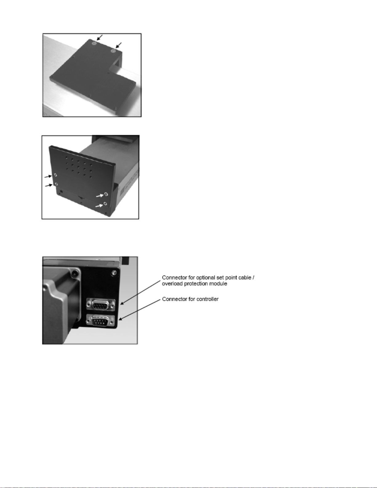
MOUNTING GRIPS AND FIXTURES
The ESMH includes a loading plate to which a grip or fixture may be
mounted. This plate can be mounted to the end of the stand with four screws
(shown at left). Before mounting the loading plate, mount the grip or fixture to
it, using the matrix of tapped holes if required.
SETTING UP THE CONTROLLER
Plug the controller cable into the 9-pin male connector beside the motor. See illustration below.
CF 171 ESMH 2 32-1034 0805
Page 3

OPERATION
Using the controller
4 5 6
4
1. SPEED CONTROL DIAL
Adjust speed by turning the dial 0.2 – 50.0 in/min [5 – 1270 mm/min].
2. LEFT
Press and hold to move the crosshead to the left, producing compressive force. Release button to stop motion.
3. RIGHT
Press and hold to move the crosshead to the right, producing tensile force. Release button to stop motion.
4. CONTROLLER CABLE
Plug this cable into the lower connector on the test stand, adjacent to the motor.
5. POWER SWITCH
Use this switch to turn on and turn off power to the load frame. Power is indicated by illuminated indicators on the face of
the controller and load frame.
6. POWER PLUG RECEPTACLE
Plug the power cord in here.
7. FUSE
1.2 A, 250V, 3AG SLO BLO
Note: To maintain smooth functioning of the stand, avoid overloads.
5
Powering up
Plug the power cord into the controller and the other end into a wall outlet. Then turn on power with the power switch
Reading the indicators
CF 171 ESMH 3 32-1034 0805
Page 4

Using the limit switches
Limit switches are included to allow the operator to set travel limits during
testing. This feature is particularly useful for spring testing, elongation testing,
and other applications where stopping at a predetermined position is a
requirement. The limit switches are located in the rear of the load frame. Their
positions can be adjusted by loosening the thumbscrews (shown at left), sliding
them to either side, and retightening. During testing, when a travel limit has been
reached, an indicator will be illuminated (see illustration above) and the
crosshead movement will stop.
About the digital travel display (optional)
The travel display covers 12” of travel with a 5-digit display (0.0005” resolution) and a computer
interface for automated data collection. Use cable P/N 09-1066 to output data to a PC.
Complete instructions are provided in a separate user’s guide (included with the digital travel
display
SPECIFICATIONS
Load capacity: 50 lb [250 N]
Speed range: 0.2-50 in/min [5-1270 mm/min]
Speed accuracy: ±5% of setting, ±0% variation with load
Maximum travel: 13.0 in [330.2 mm]
Maximum travel w/travel display: 12.0 in [304.8 mm]
Power: Universal input 80-240 VAC, 50/60 Hz
Fuse type: 1.2 A, 250V, 3AG SLO BLO
Weight (test stand only): 17 lb [7.7 kg]
Controller weight: 2.7 lb [1.2 kg]
DIMENSIONS IN [MM]
CF 171 ESMH 4 32-1034 0805
Page 5

WARRANTY REPAIR POLICY
Limited Warranty on Products
Any Cooper Instruments product which, under normal operating conditions, proves defective in material or in
workmanship within one year of the date of shipment by Cooper will be repaired or replaced free of charge
provided that a return material authorization is obtained from Cooper and the defective product is sent,
transportation charges prepaid, with notice of the defect, and it is established that the product has been
properly installed, maintained, and operated within the limits of rated and normal usage. Replacement or
repaired product will be shipped F.O.B. from our plant. The terms of this warranty do not extend to any
product or part thereof which, under normal usage, has an inherently shorter useful life than one year. The
replacement warranty detailed here is the buyer’s exclusive remedy, and will satisfy all obligations of Cooper
whether based on contract, negligence, or otherwise. Cooper is not responsible for any incidental or
consequential loss or damage which might result from a failure of any and all other warranties, express or
implied, including implied warranty of merchantability or fitness for particular purpose. Any unauthorized
disassembly or attempt to repair voids this warranty.
Obtaining Service under Warranty
Advance authorization is required prior to the return to Cooper Instruments. Before returning the item,
contact the Repair Department c/o Cooper Instruments at (540) 349-4746 for a Return Material Authorization
number. Shipment to Cooper shall be at buyer’s expense and repaired or replacement items will be shipped
F.O.B. from our plant in Warrenton, Virginia. Non-verified problems or defects may be subject to a $150
evaluation charge. Please return the original calibration data with the unit.
Repair Warranty
All repairs of Cooper products are warranted for a period of 90 days from date of shipment. This warranty
applies only to those items that were found defective and repaired; it does not apply to products in which no
defect was found and returned as is or merely recalibrated. It may be possible for out-of-warranty products
to be returned to the exact original specifications or dimensions.
* Technical description of the defect: In order to properly repair a product, it is absolutely necessary for
Cooper to receive information specifying the reason the product is being returned. Specific test data, written
observations on the failure and the specific corrective action you require are needed.
CF 171 ESMH 5 32-1034 0805
 Loading...