

Page 1

ELF 4200
Load and Force System
Single Handle, Multi-Handle, and Hi-Speed Systems
Version 3.10
USER’S GUIDE
www.cooperinstruments.com
PH: 540-349- 4746 • FAX: 540-347-4755
Page 2

CONTENTS
1.0 INTRODUCTION....................................................................................................................1
2.0 QUICK START.......................................................................................................................1
3.0 INSTALLATION .....................................................................................................................4
3.1 Software Installation.......................................................................................................................6
3.2 Hardware Installation....................................................................................................................10
4.0 OVERVIEW ..........................................................................................................................10
4.1 Sensors..........................................................................................................................................11
4.2 Sensor Handle...............................................................................................................................11
4.3 Screen Display ..............................................................................................................................11
4.3.1 Screen Display........................................................................................................................11
4.3.2 Main Window ..........................................................................................................................11
Movie Window .................................................................................................................................13
4.4 THE MAIN MENU...........................................................................................................................14
4.4.1 The Main Menu .......................................................................................................................14
4.4.2 File Menu.................................................................................................................................14
4.4.3 Edit Menu................................................................................................................................16
4.4.4 View Menu...............................................................................................................................17
4.4.5 Record Menu...........................................................................................................................19
4.4.6 Tools Menu .............................................................................................................................22
4.4.7 Window Menu.........................................................................................................................26
4.4.8 Frames Displayed Menu........................................................................................................26
4.4.9 Help Menu...............................................................................................................................27
5.0 SENSOR LOADING CONSIDERATIONS............................................................................28
5.1 SENSOR LOADING .......................................................................................................................28
5.2 SATURATION ................................................................................................................................28
5.3 CONDITIONING SENSORS...........................................................................................................29
6.0 CALIBRATION.....................................................................................................................29
6.1 CALIBRATION GUIDELINES ........................................................................................................30
6.2 CALIBRATION PROCEDURE .......................................................................................................31
7.0 SENSOR PERFORMANCE CHARACTERISTICS ..............................................................35
7.1 REPEATABILITY ...........................................................................................................................35
7.2 LINEARITY.....................................................................................................................................35
7.3 HYSTERESIS .................................................................................................................................36
7.4 DRIFT .............................................................................................................................................36
7.5 TEMPERATURE SENSITIVITY......................................................................................................36
7.6 SENSOR LIFE / DURABILITY .......................................................................................................36
8.0 USING THE ELF LABVIEW VI’S.........................................................................................36
8.1 LABVIEW VI INSTALLATION........................................................................................................36
8.2 VI’S .................................................................................................................................................36
8.2.1 VISA Sessions........................................................................................................................37
8.2.2 Getting Started VI...................................................................................................................37
8.2.3 Tekscan-ELF App Example...................................................................................................37
8.2.4 Tekscan-ELF Loop Example .................................................................................................37
8.2.5 Initialize...................................................................................................................................38
8.2.6 Close .......................................................................................................................................38
8.2.7 Sensitivity ...............................................................................................................................38
CF10 ii 03/03/04 REVC
Page 3

8.2.8 Read ........................................................................................................................................39
GLOSSARY ...............................................................................................................................39
7.0 WARRANTY REPAIR POLICY............................................................................................45
Limited Warranty On Products..........................................................................................................45
Obtaining Service Under Warranty....................................................................................................45
Repair Warranty ..................................................................................................................................45
CF10 iii 03/03/04 REVC
Page 4
1.0 INTRODUCTION
This manual describes how to use FlexiForce’s Economical Load & Force (ELF) system , Multi-Handle ELF and Hi-
Speed ELF. These systems are ideal for designers, researchers, or anyone who needs to measure forces without
disturbing the dynamics of their tests. The FlexiForce sensors can be used to measure both static and dynamic
forces (up to 1000 lbf), and are thin enough to enable non-intrusive measurement.
Each ELF system is comprised of FlexiForce’s Microsoft (MS) Windows
electronics, and SSB-F (Single Sensing Button - FlexiForce) sensors. The ELF system hardware includes the
sensor handle with serial adapter, and the sensors. One of the major advantages of this system is that it is simple
to install, and requires very little hardware.
The ELF sensors use a resistive-based technology. The application of a force to the active sensing area of the
sensor results in a change in the resistance of the sensing element in inverse proportion to the force applied. After
a simple calibration is performed, this force can be displayed on the screen in the measurement units that you
choose, such as pounds or Newtons.
The ELF software is a 32-bit application that is compatible with Microsoft (MS) Windows 95/98/ME/2000 and XP.
The software allows you to view a graphical representation of the force on the sensor in real time, record this
information as a ‘movie’, and review and analyze it later. There are a number of options for displaying the realtime
force data; it can be displayed as a strip chart, meter, column graph, or digital readout. Recorded ‘movie’ frames
can be saved as ASCII (text) files, which can be imported into a spreadsheet program, or opened in a text editor or
word processing program. Realtime data or movie frames can also be copied to the Windows clipboard and pasted
into other applications as a .bmp (bitmap) file.
TM
-based software, the associated
2.0 QUICK START
This is a quick look at how to use your ELF system. This Quick Start procedure should be followed as a general
outline; it will give you the basics on how to view sensor force data in a Real-time Window, record this data, play
the recording back, and analyze the data. However, you must read the entire manual before designing your
application.
Note: This procedure assumes that the ELF software has been successfully installed on your system. In
addition, a familiarity with MS Windows is assumed.
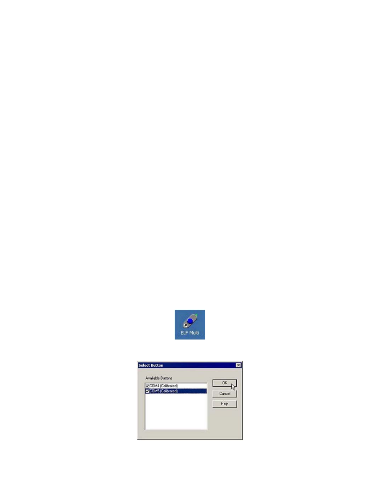
1. Make sure the sensors are inserted correctly into the handles. Run the program by clicking the Start button at
the bottom left of the screen, selecting Programs, and then clicking the ELF Multi icon.
2. If you have the Multi-Handle ELF system and have connected multiple handles, you will be prompted to select
the COM ports/handles you wish to use for testing. Click to place a check in each box, and then select OK.
CF10 1 03/03/04 REVC
Page 5
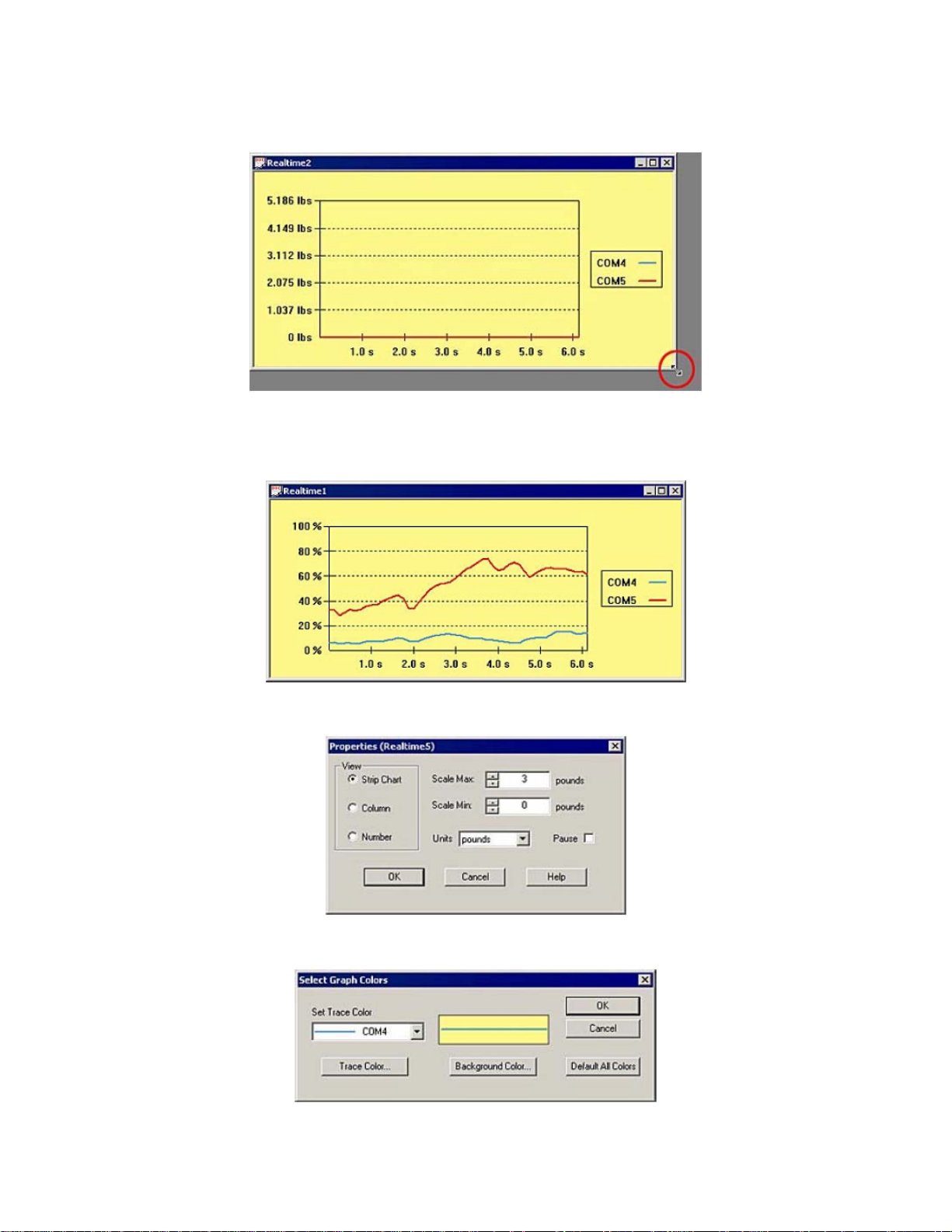
3. A new Real-time window will appear. The size of this window will vary, since MS Windows cascades new
windows. If the window is too small to view comfortably, enlarge it by dragging an edge of the window with the
cursor (shown below).
4. Apply the test force to the sensing area of the sensors (refer to the “Sensor Loading Considerations” section
and ensure that the sensors are conditioned before use). The force data will be displayed in the window in the
default mode, which is as a "Strip Chart". This shows the data in the form of a chart, with elapsed time (in
seconds) on the X-axis, and the selected units (default is "percentage") on the Y-axis.
5. Click on View -> Properties (or click the right mouse button with the cursor over the Real-time Window) to
open the Properties dialog box. Make any desired changes to the display settings, and click OK.
6. If you would like to change the background color of the window, select Tools -> Select Colors. The Select
Graph Colors dialog box will open, and enable you to customize the background color.
CF10 2 03/03/04 REVC
Page 6
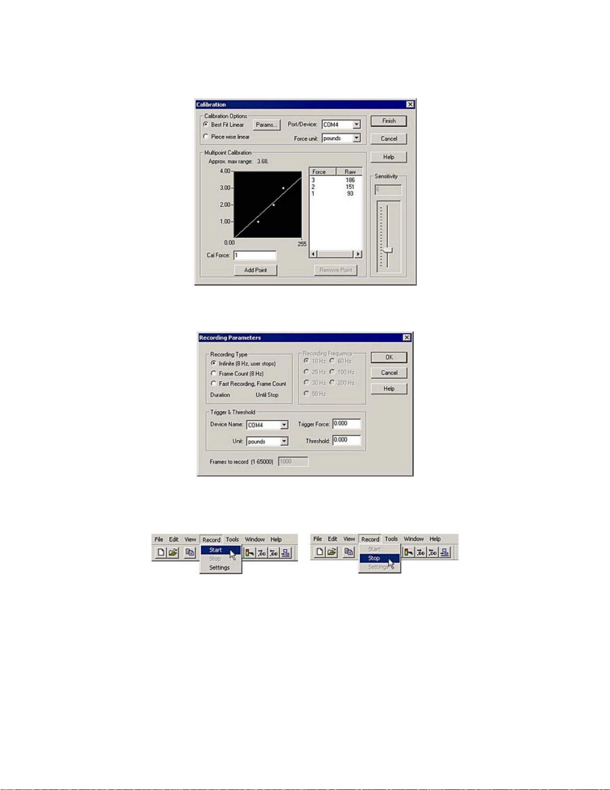
7. Calibrate the sensor(s), so that an actual force range can be determined for the sensor’s digital output (0 to
255). Refer to the “Calibration” section for the calibration procedure and guidelines. It is also recommended that
you perform a "Sensitivity Adjustment", which is described in the "Calibration" section.
8. Select the desired recording parameters under Record -> Settings. The default Recording Type is "Infinite (8
Hz, user stops)", but you are given the option to stop the recording after a specific number of frames. You may
also set recording frequency, trigger and threshold, as well as frames to record, in this dialog box.
9. Click Record -> Start (or the Start Recording icon on the Toolbar). The system will begin recording data. If
you selected "Infinite (8 Hz, user stops)" as the recording type, you must click Record -> Stop (or the Stop
Recording icon on the Toolbar) to stop recording. Otherwise, recording will stop when the required number of
frames have been acquired.
Note: Before an actual recording is made, the sensor should be Calibrated and Conditioned, and a
Sensitivity Adjustment should be done (if necessary), as described in later sections. Any information
recorded before these are successfully completed may be inaccurate.
The ELF software also allows you to trigger the start of a recording. If you enter a value in the Trigger Force field
under Record -> Settings, recording will not begin until that force is exerted on the sensor. Force threshold may be
selected for each sensor, so that a recording will not begin until the force reaches the threshold. See the
“Calibration” section for more details.
CF10 3 03/03/04 REVC
Page 7
10. Select File -> Save As to save the movie. Under File Name, enter the desired file name (e.g.: "test1.flf") and
select the destination (path) where you want to save your recording. Recordings must be saved as ELF Movie
Files (with the extension *.flf).
11. Click on one of the Playback Control icons on the toolbar at the top of the Movie window to play the movie
forward or backward, move one frame forward or backward, move to the first or last frame, or stop the movie.
12. Select Edit -> Copy, or click the Copy icon on the Toolbar. The contents of the window will be copied to the
Windows clipboard, and will be available to be pasted as a graphic (bitmap) into other Windows applications.
13. Select File -> Save ASCII to save the movie data as a text file. ASCII files must be saved with the extension
*.csv. This data can then be viewed by importing it into a spreadsheet program, such as MS Excel, or by
opening the text file in a word processing program, such as MS Word.
You have now completed the Quick Start section, and should be acquainted with your ELF software. The
rest of the manual gives you specific instructions on how to set up and run your system.
3.0 INSTALLATION
For the ELF software to function properly, your system must have the following minimum requirements:
• Pentium 300 MHz
• 64 MB RAM
• 5 MB of Hard Drive Space
• CD Drive
• One 9-pin RS-232 port per ELF handle
• Windows 95/98/ME/2000/XP
To use the Multi-Handle ELF software with multiple RS-232 serial ports, one port must be available for each ELF
handle used. To meet the power requirements for the ELF handle and FlexiForce sensor, compatible serial ports
must generate at least 7 Volts each from the DTR and RTS pins. They also must be labeled with a distinct COM
port number. The following products have been tested with the ELF multi-handle system and were found to be
compatible at the time of testing. Not all products from each manufacturer have been tested. It is possible that other
products from these manufacturers with similar specifications will also be compatible with the ELF system.
CF10 4 03/03/04 REVC
Page 8
NOTE: For the Hi-speed Multi-Handle ELF software: If using Windows 2000/XP you will need a PCI board
and we would recommend that you use no more than 4 handles. If using Windows 95/98/ME you will need
either a PCI board or USB adapter.
Quatech, Inc.
662 Wolf Ledges Parkway
Akron, OH 44311 USA
T: (800)-553-1170 T: (330)-434-3154
F: (330)-434-1409
E-Mail: sales@quatech.com
Web: www.quatech.com
Quatech PCI boards
QSC-100 Four Port RS-232 PCI Serial Board:
http://www.quatech.com/shopquatech/products/prod338.asp
Alternate cable with four D-9 serial connectors is required for ELF
Quatech USB adapters
SSU-100One Port RS-232 Serial USB Adapter with 9-pin connector
http://www.quatech.com/shopquatech/products/prod4324.asp
QSU-100 Four Port RS-232 Serial USB Adapter
http://www.quatech.com/shopquatech/products/prod268.asp
ESU-100 Eight Port RS-232 Serial USB Adapter
http://www.quatech.comshopquatech products/prod4325.asp
Measurement Computing, Corp.
16 Commerce Boulevard
Middleboro, MA 02346
T: (508) 946-5100 F: (508) 946-9500
E-Mail: info@measurementcomputing.com
Web: www.measurementcomputing.com
Measurement Computing PCI Boards
PCI-COM232/4-9 Four Port RS-232 Interface with 9 pin adapters
www.measurementcomputing.com
CF10 5 03/03/04 REVC
Page 9
3.1 Software Installation
Before installing the ELF software, close all other applications. To install the software, place the CD-ROOM in your
CD-ROM drive. If the autorun.exe does not start automatically, click on Start at the bottom left of the screen, and
click on the Run menu item. If you put the disk in the D: CD-ROM drive, type ‘d:setup’ in the Command Line field of
the Run dialog box, then click <OK>. The following images outline the installation process:
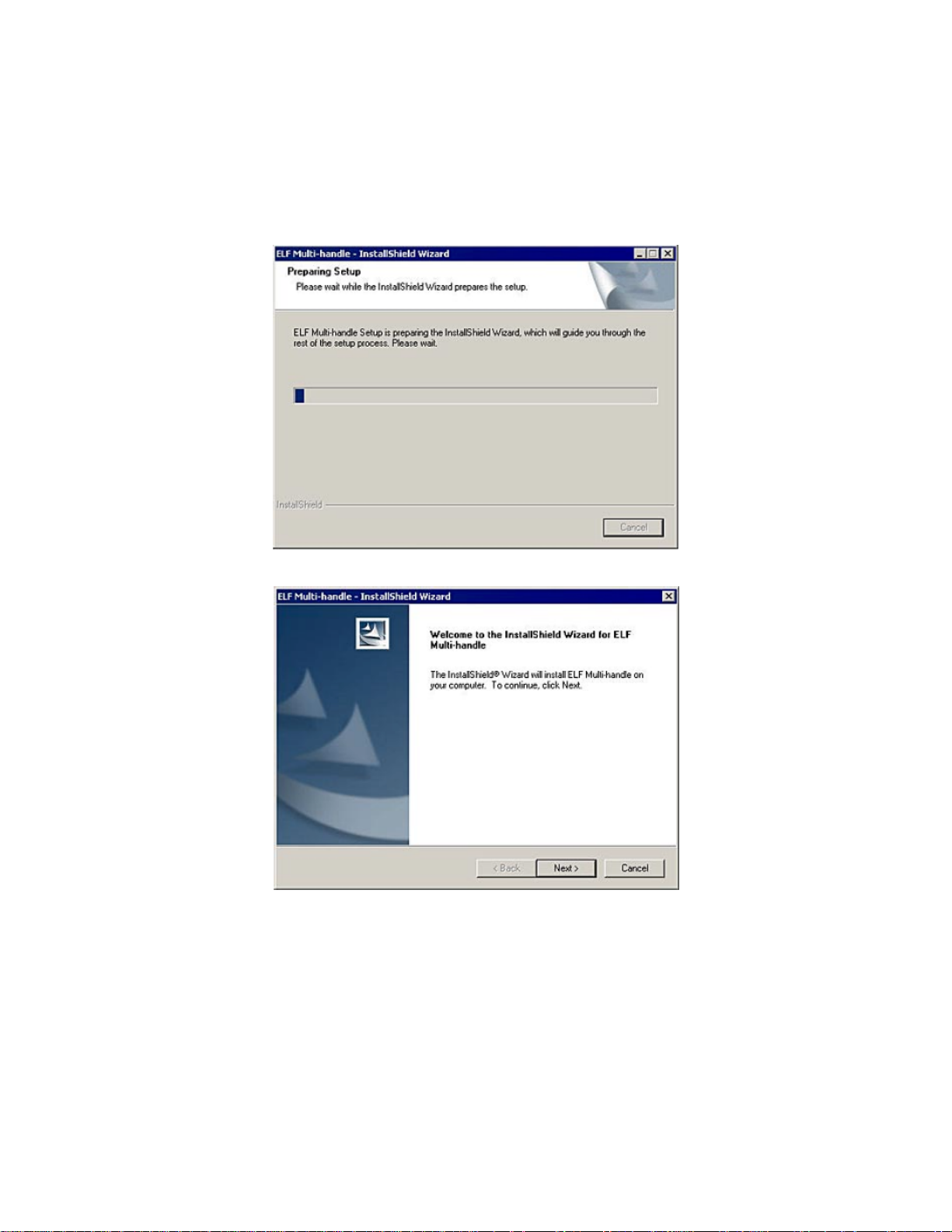
First, the InstallShield Wizard will prepare your machine for proper setup:
The next screen you will see is the Welcome screen. Click Next to continue with the Setup.
You will be taken to the License Agreement page. When you have read the License and agree to the terms, click
the Next button to continue with your installation.
CF10 6 03/03/04 REVC
Page 10
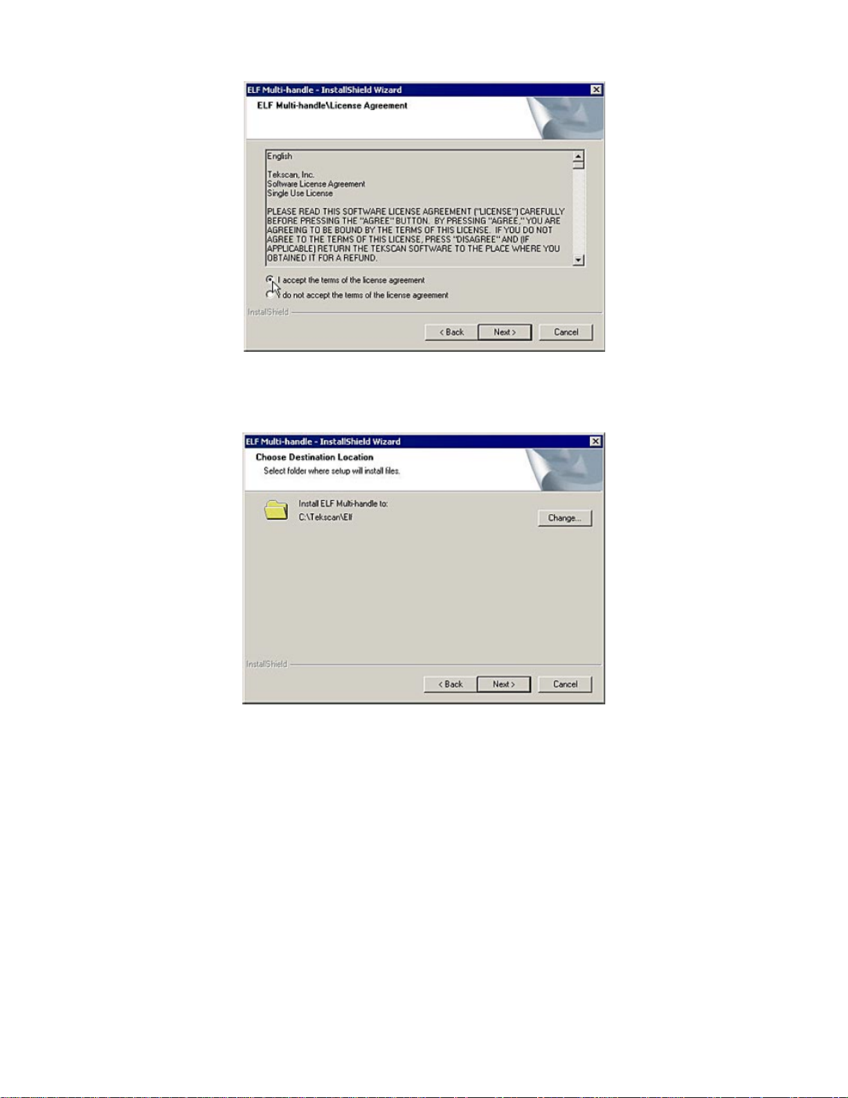
Next, the installation program will copy the necessary files to your computer. The default location is
C:\Tekscan\Elf, however, you can change this location by clicking the Change button and designating a
destination of your choice on your computer’s hard drive.
At this point, your computer has the necessary information to proceed with the installation of your ELF program.
Click the Install button to begin installing the program on your computer.
CF10 7 03/03/04 REVC
Page 11
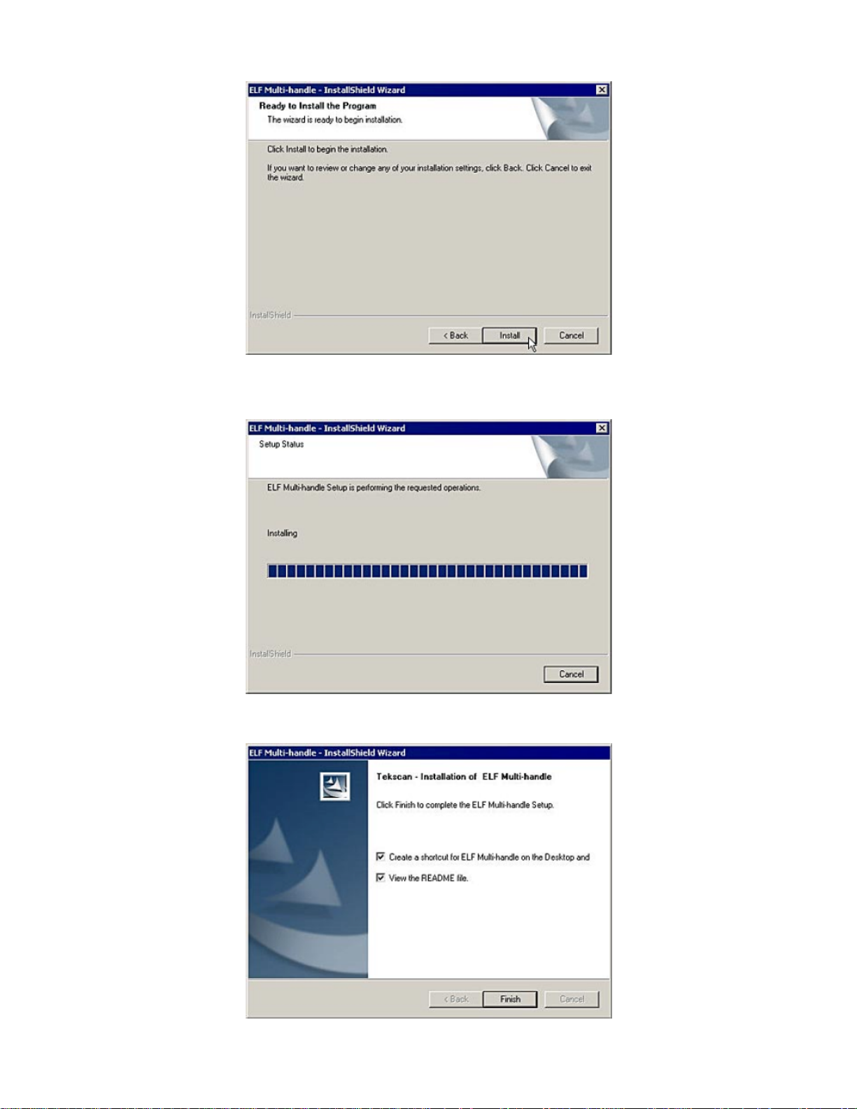
A progress bar will indicate the program is being successfully installed.
Note: If, at any time prior to this screen you wish to stop the installation process, you can click the Cancel
button.
The next screen that will appear offers you the options to place a shortcut icon on your desktop and view the
README file.
CF10 8 03/03/04 REVC
Page 12
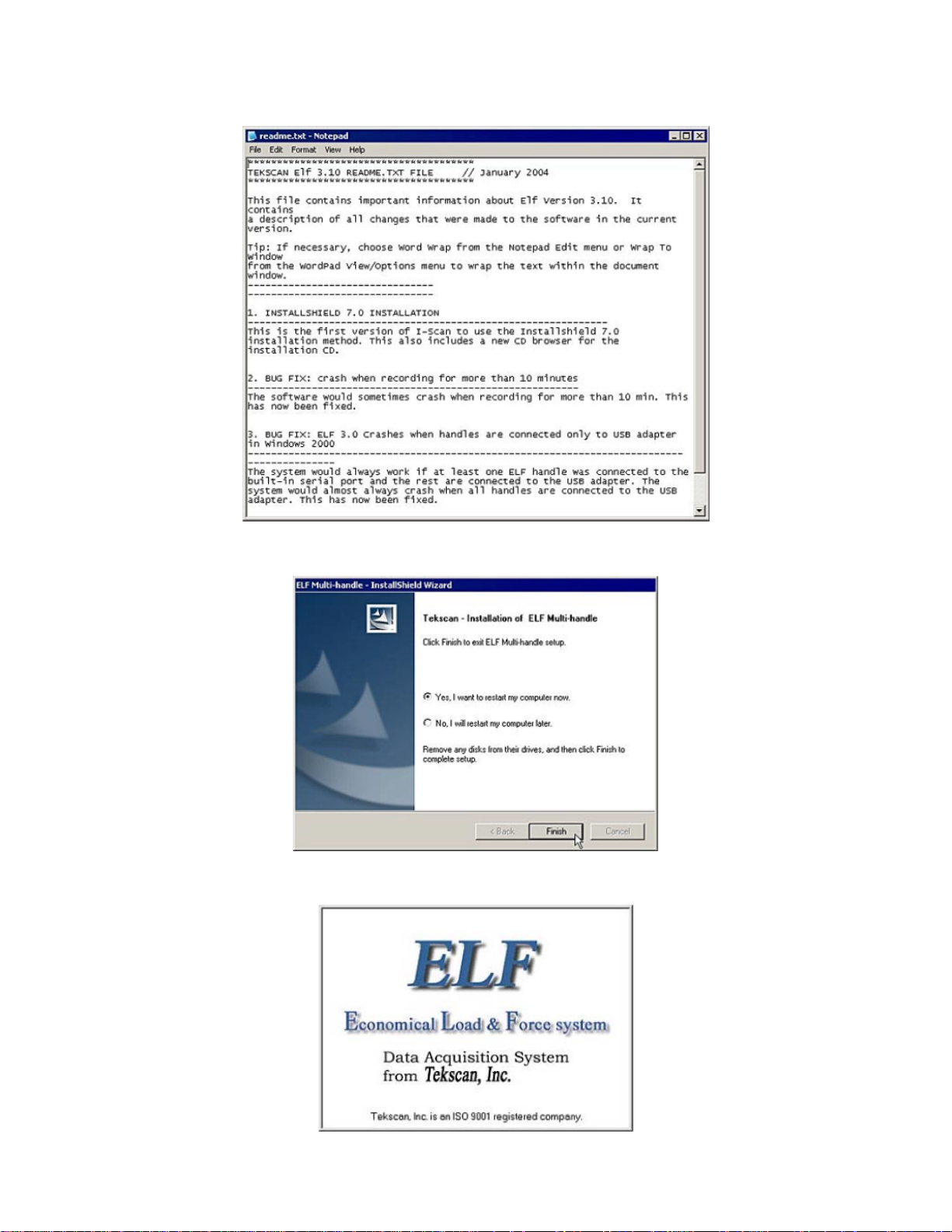
If you elect to view the README file, it will open in a MS Notepad window, where you can read about new and
updated information regarding the latest release of the ELF software.
When the installation is completed, you will need to restart your system. Click the Finish button, and your system
will be automatically rebooted. You cannot start the ELF software without first restarting.
The ELF splash screen will be shown (below). This indicates the ELF software is successfully loaded on your
machine.
CF10 9 03/03/04 REVC
Page 13
The installation process is now complete. When your computer is rebooted, the application can then be launched
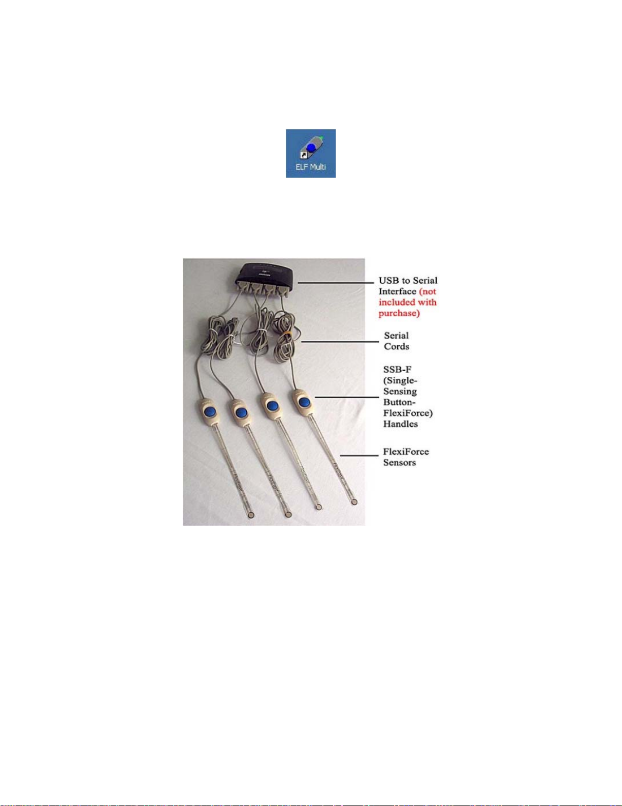
by clicking on the Start button at the bottom left of the screen, and selecting Programs -> Tekscan -> ELF Multi.
You can also launch the program by double-clicking the ELF Multi icon on your desktop (provided you opted to
place an icon on your desktop during the installation procedure).
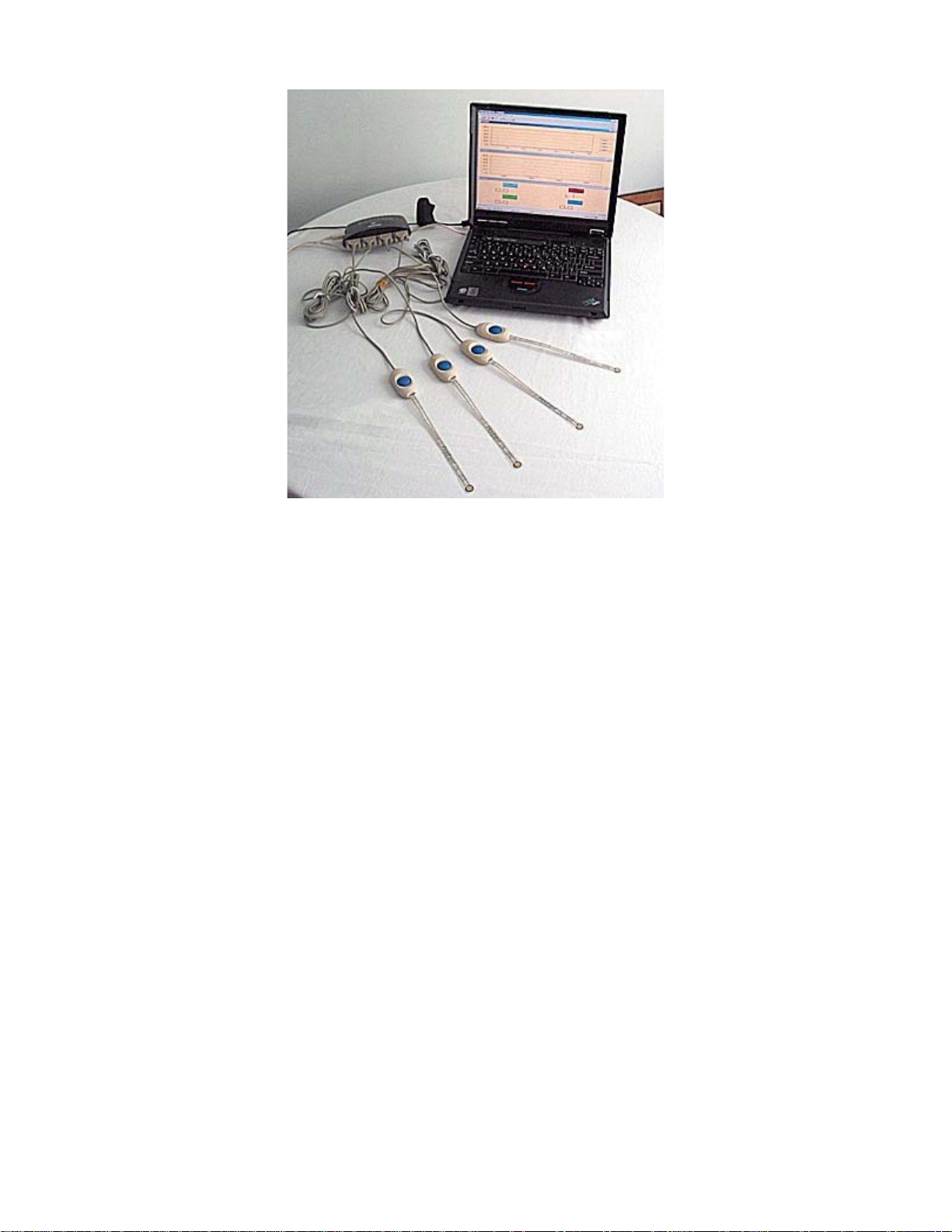
3.2 Hardware Installation
The ELF system hardware includes the sensor Handle(s), ELF software, and the SSB-F (Single Sensing Button -
FlexiForce) sensors. If you are using the Multi-Handle ELF system, refer to the instructions included with the
individual "PCI board" or "USB-Serial interface box" for installation. Connect one ELF handle to each COM port you
wish to use during testing.
To install the sensor handle, connect its plug to one of the receptacles on the adaptor plug. To insert a sensor into
the handle, ensure that the "UP" printed on the sensor is correctly oriented (on the same side as the blue button on
the handle), and then press down the blue button. Slide the sensor tab into the slot until it reaches its mechanical
stop, and release the blue button.
Do not force the sensor if it will not slide into the handle easily. If the sensor will not slide in easily, check that there
is nothing inside the handle blocking the sensor, and check that the end of the sensor is not bent or folded.
If the software has been installed, and is running, when the sensor is correctly inserted, an audible beep will be
heard, and the "Sensor OK" icon on the Toolbar will be a green square; otherwise it will be "grayed out".
Note: Follow Static control procedures when handling the sensor while it is in use.
4.0 OVERVIEW
This section outlines the Various Hardware and Software components that ship with your system.
CF10 10 03/03/04 REVC
Page 14

4.1 Sensors
The sensor is an ultra-thin and flexible printed circuit. Sensors are available in three full-scale force ranges: Low
(25 lbf ), Medium (150 lbf ), and High (1000 lbf ). The "active sensing area" is a 0.375. diameter circle at the end of
the sensor. The sensors are constructed of two layers of substrate, such as a polyester film. On each layer, a
conductive material (silver) is applied, followed by a layer of pressure-sensitive ink. Adhesive is then used to
laminate the two layers of substrate together to form the sensor. The "active sensing area" is defined by the silver
circle on top of the pressure sensitive ink. Silver extends from the sensing area to the connectors at the other end
of the sensor, forming the conductive leads.
The sensor acts as a variable resistor in an electrical circuit. When the sensor is unloaded, its resistance is very
high (greater than 5 Meg-ohm); when a force is applied to the sensor, the resistance decreases. This resistance is
read, and an 8-bit analog-to-digital converter changes the output to a digital value in the range of 0 to 255.
4.2 Sensor Handle
The sensor’s tab is placed into the sensor handle. The handle gathers data from the sensor, processes it, and
sends it to your computer through a serial port.
4.3 Screen Display
4.3.1 Screen Display
This section is a comprehensive look at the ELF screen display. Each component of the display, as well as each
Main Menu option, will be described in detail.
Note: Familiarity with MS Windows is assumed, so menu items that have the same function in standard
Windows applications are not described in this manual.
4.3.2 Main Window
When you initiate the ELF software program, the Main Window is displayed on your computer screen. The Main
Window consists of the Menu Bar, Tool Bar, and Main Status Bar, and may contain one or more Real-time or
Movie Windows. The window that is selected is considered the active window. Only one window can be active at
one time, and the title bars of the other windows will be grayed out. The Main Window, and its components, are
shown in the figure below.
CF10 11 03/03/04 REVC
Page 15
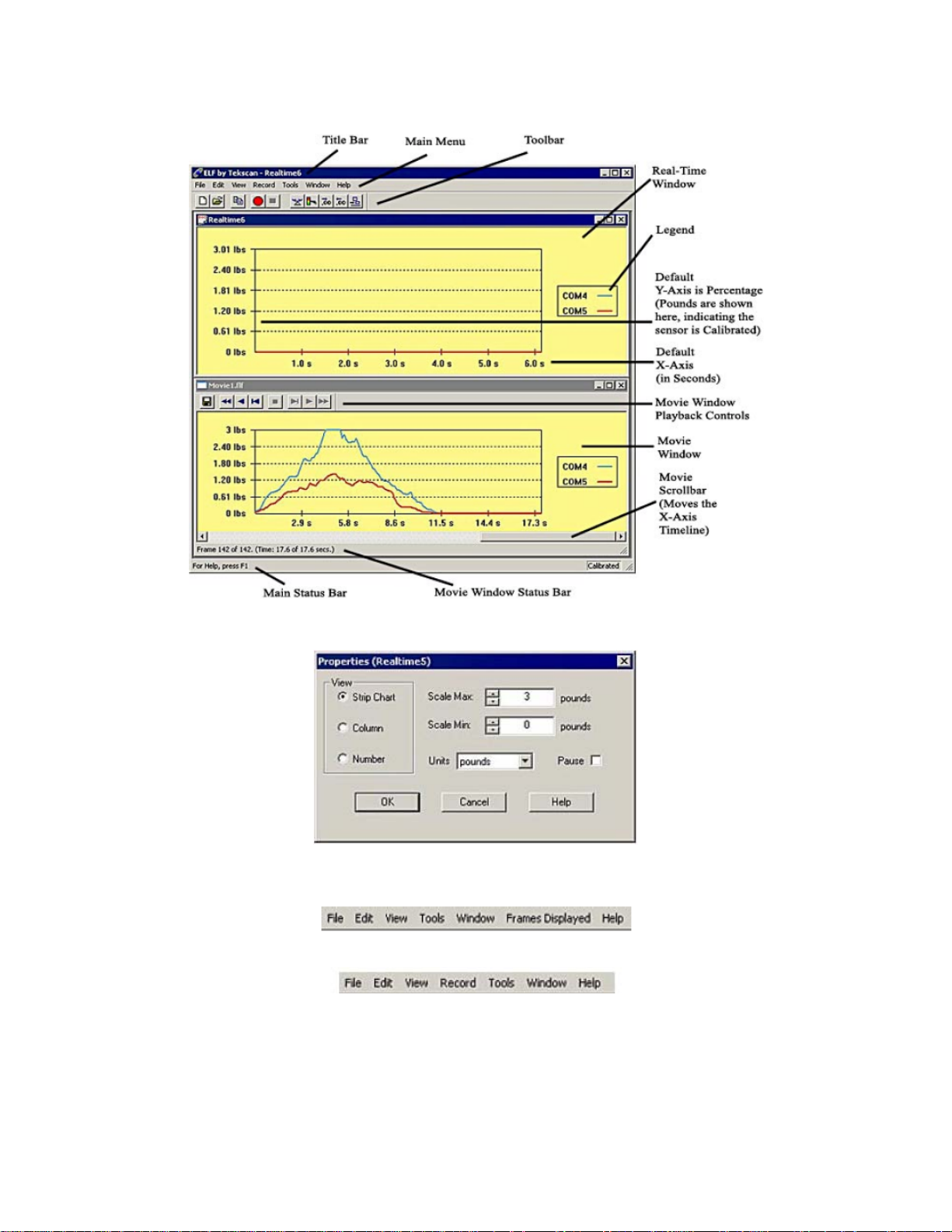
NOTE that the figure below shows a Multi-Handle ELF system with two handles recording data.
Real-Time Window: displays the load applied to the sensor as it is happening (in real-time). The Properties of this
display can be changed in the File pull-down menu, or by clicking the right mouse button.
Menu Bar: provides drop-down menus used to control the program. It is located at the top of the Main Window.
The Main Menu as it appears when focus is on a Movie Window:
The Main Menu as it appears when focus is on a Real-time Window:
Note: for more information, see the Main Menu section.
Toolbar: provides some of the same options as the Menu Bar, but with icons replacing drop-down menus. It is
located directly below the Menu Bar, at the top of the Main Window. Note that not all items in the Menu Bar have a
corresponding icon on the Toolbar.
CF10 12 03/03/04 REVC
Page 16

Two icons on the Toolbar do not have corresponding pull-down menus. They are the Increase Decimal and
Decrease Decimal buttons. When sensors have been calibrated, units of force will be shown. Clicking these
buttons will either increase or decrease the number of decimal places displayed by the software.
Main Status Bar: will either say "For Help, Press F1," or will give a description of whichever Toolbar icon is under
the cursor. The Main Status Bar is located at the bottom of the Main Window.
Movie Window
The Movie Window displays a previously recorded movie. It consists of the display area, a scroll bar, the Movie
Toolbar with playback controls, and the Movie Window Status Bar.
Movie Tool Bar: This bar is located at the top of the Movie Window, and consists of the movie playback icons and
the Save As icon.
• Τhe Save As icon allows you to save the current movie file under a different filename.
The Playback icons control the movie playback functions. They are (from left to right in the Movie Toolbar):
• First Frame: Positions the recording at the beginning (first frame).
• Play Backward: Plays the recording in reverse.
• Previous Frame: Plays the recording in reverse one frame each time it is clicked.
• Stop: Stops playback.
• Next Frame: Plays the recording forward one frame each time it is clicked.
• Play Forward: Plays the recording forward.
• Last Frame: Positions the recording at the end (last frame)
CF10 13 03/03/04 REVC
Page 17

• Movie Window Status Bar is located at the bottom of the Movie Window, and displays the "Frame count"
(the current frame number vs. the total number in the movie). Directly above this status bar is a "scroll bar",
which can be used to move to any point (frame) in the movie.
4.4 THE MAIN MENU
4.4.1 The Main Menu
The Main Menu contains important commands you use to perform functions within the software. Some menu
commands can be found directly in the toolbar, however, not all commands found under the menu are located on
the toolbar. For this reason, it is important to become acquainted with the commands found under each menu. This
section provides a thorough description of each command and dialog box found under these menus.
It is important to note that the Main Menu changes, depending where your "focus" lies. The reason for this
difference is because there are some commands that can only be accessed from a Movie Window, and others from
a Real-time Window. For example, if you have two windows open, one a Real-time Window, and the other a Movie
Window, the Main Menu will contain a different set of submenus and commands. The following display shows the
difference between the two Main Menus:
The Main Menu as it appears when focus is on a Movie Window:
The Main Menu as it appears when focus is on a Real-time Window:
4.4.2 File Menu
File Menu when focus is on a real-time window:
File Menu when focus is on a movie window:
New: opens a new Real-time Window, in addition to any other Real-time or Movie windows that are currently open.
The new Real-time Window becomes the active window when it is opened. If more than one Real-time Window is
CF10 14 03/03/04 REVC
Page 18

open, the force data will be displayed in all windows, in unison. If the sensor has already been calibrated, this
calibration will also apply to the new Real-time Window.
Before your Real-time Window opens, the Select Button dialog box is displayed. Handles connected to your system
are listed as "COM 4", "COM 5", etc. Select the handles you wish to have displayed in your Real-time Window by
placing a checkmark next to the COM port(s), and then click the OK button.
You are then taken to a new Real-time Window:
Open: displays the Open dialog box, which allows you to open previously recorded movie files. Only ELF movie
files, with the *.flf file extension, can be opened.
Close: causes the currently active Real-time or Movie Window to close. If a movie has been recorded, but not
saved, the software gives the option of saving the movie file.
Save As: will save the current movie with the specific file name and location of your choice. ELF movie files must
have the extension *.flf. Your system may limit filenames to eight characters. This menu item can be used to save
a movie file under more than one filename.
CF10 15 03/03/04 REVC
Page 19

Save As ASCII: saves the current Movie frame as an ASCII file, with the extension *.csv. Since these files are in
ASCII (comma separated value) format, they can be imported into a spreadsheet program (e.g. MS Excel), or
they can be opened in a text editor or word processing program (e.g. MS Word) in order to review and manipulate
the data.
The force data is displayed as however many sensors you are measuring (1-16); the first is the elapsed time (in
seconds), and the others are the applied force value (in the selected units) at that point (shown below). A data point
is recorded each time the sensor data is read, so many more data points are recorded when "Fast Recording" is
used (refer to the Settings menu item).
Seconds Sensor 1 Sensor 2 Sensor 3
0 7.894737 5.263158 5.263158
0.125 44.73684 15.78947 5.263158
0.25 97.36842 92.10526 15.78947
0.375 134.2105 171.0526 73.68421
4.4.3 Edit Menu
Edit Menu (same when focus is on either a Real-time or Movie Window):
Copy: saves the current Real-time or Movie frame to the MS Windows clipboard. This data is saved in the
clipboard as a graphic (bitmap) image of the current window. Once copied to the clipboard, this data can be pasted
into other Windows applications by selecting Edit -> Paste.
The following image shows how the copy command can be used to import an image of the current window into MS
Excel:
CF10 16 03/03/04 REVC
Page 20

4.4.4 View Menu
View Menu when focus is on a Real-time Window:
View Menu when focus is on a Movie Window:
Strip Chart: is the default display mode, where force value is displayed on the Y-Axis and elapsed time is
displayed on the X-Axis.
Column: displays each COM port individually, with force value displayed on the Y-Axis. Each column is colorcoded to indicate the individual COM ports. As time elapses, the columns indicate changes in force.
CF10 17 03/03/04 REVC
Page 21

Number: displays each COM port as numerical values. Each numerical value is color coded to indicate the
individual COM ports. As time elapses, the numbers change to indicate changes in force.
Toolbar: This item is used to display or hide the Movie and Main Toolbars. These toolbars can be toggled by
clicking this menu item on and off. If a Real-time Window is active, this menu item affects the Main Toolbar. If a
Movie window is active, this menu item affects the Movie Toolbar.
Status Bar: This item is used to display or hide the Movie and Main Status Bars. These status bars can be toggled
by clicking this menu item on and off. If a Real-time window is active, this menu item affects the Main Status Bar. If
a Movie window is active, this menu item affects the Movie Status Bar.
Properties: opens the Properties dialog box (shown following), which allows you to change how the data is
displayed on the screen. Any changes made here will only affect the currently active Real-time or Movie Window.
The Properties dialog box will also appear whenever you click the right mouse button over a Real-time or Movie
Window.
Under View, you can select whether to display the force data as a Strip Chart, Column, or Number. Strip Chart
shows the pressure data in the form of a chart, with elapsed time (in seconds) on the X-axis, and the selected units
on the Y-axis. Column displays the data as a single column, with the force values on the Y-axis. Number displays
the force data as a digital readout.
CF10 18 03/03/04 REVC
Page 22

In the Properties dialog box, you may also change the Scale Max, Scale Min, and Units. Under Units, the display
units (Percentage, Grams, Kilograms, Newtons, and Pound) are selected. Scale Min and Scale Max set the range
of values that will be displayed. Certain default maximum and minimum values will be displayed for the selected
units, and these values can be changed by clicking on the up and down arrows to the right of the numbers.
Selecting Pause causes the current Real-time window to "freeze", or to ignore all commands. When this is
selected, the word "Pause" will be added to the Title Bar of the window. Movie windows cannot be paused.
4.4.5 Record Menu
Record Menu (only available when focus is on a Real-time Window):
Start: is used to make a recording (movie). When this is selected, the software begins recording a movie of the
current Real-time window data using the settings that have been selected (see the "Settings" menu item below).
When data is being recorded, the Recording message will appear (shown below), and the "Recording On" icon (on
the Main Toolbar) will become active (the red circle will become "grayed out", and the square "Stop" button -- black
color -- will become visible). If "Triggering" is in effect, and Record is selected, the "Waiting for Trigger" message
will be displayed until the trigger force is reached. Movies created by the ELF system are stored as *.flf files.
Stop: will cause the software to stop recording the active Real-time Window, even if the correct number of movie
frames (as selected in "Settings") have not yet been recorded.
Settings: brings up the Recording Parameters dialog box, which allows you to change the current recording
parameters. Under .Recording Type,. there are three possibilities that may be selected.
Note: The Frequency, or acquisition rate, is measured in Hertz (Hz), which is the number of times per
second the sensor output is read by the software.
Standard ELF Recording Parameters
If you have purchased the standard ELF system, the software will record at a lower range of speeds, and your
choices for ‘Recording Types’ include Infinite, Frame Count and Fast Recording (below).
CF10 19 03/03/04 REVC
Page 23

When Infinite is selected, recording will continue until Stop is selected (from the Record menu or by clicking its
icon on the Toolbar).
When Frame Count is selected, the number of "Frames to Record" may be entered at the bottom of the dialog box.
The recording will stop when this number of frames has been recorded, regardless of the duration of the movie.
When Fast Recording, is selected, the "Frames to Record" may be entered, and the Recording Freque ncy (Hz)
may be selected to the right. In "Fast Recording" applications, recordings can be obtained at frequencies of 10, 25,
30, 50, 60, 100, and 200 Hz.
The Duration is listed below the Recording Type; it will either say "Until Stop" if Infinite is selected, or the
approximate duration (in seconds) the recording will take to complete if Frame Count is specified.
CF10 20 03/03/04 REVC
Page 24

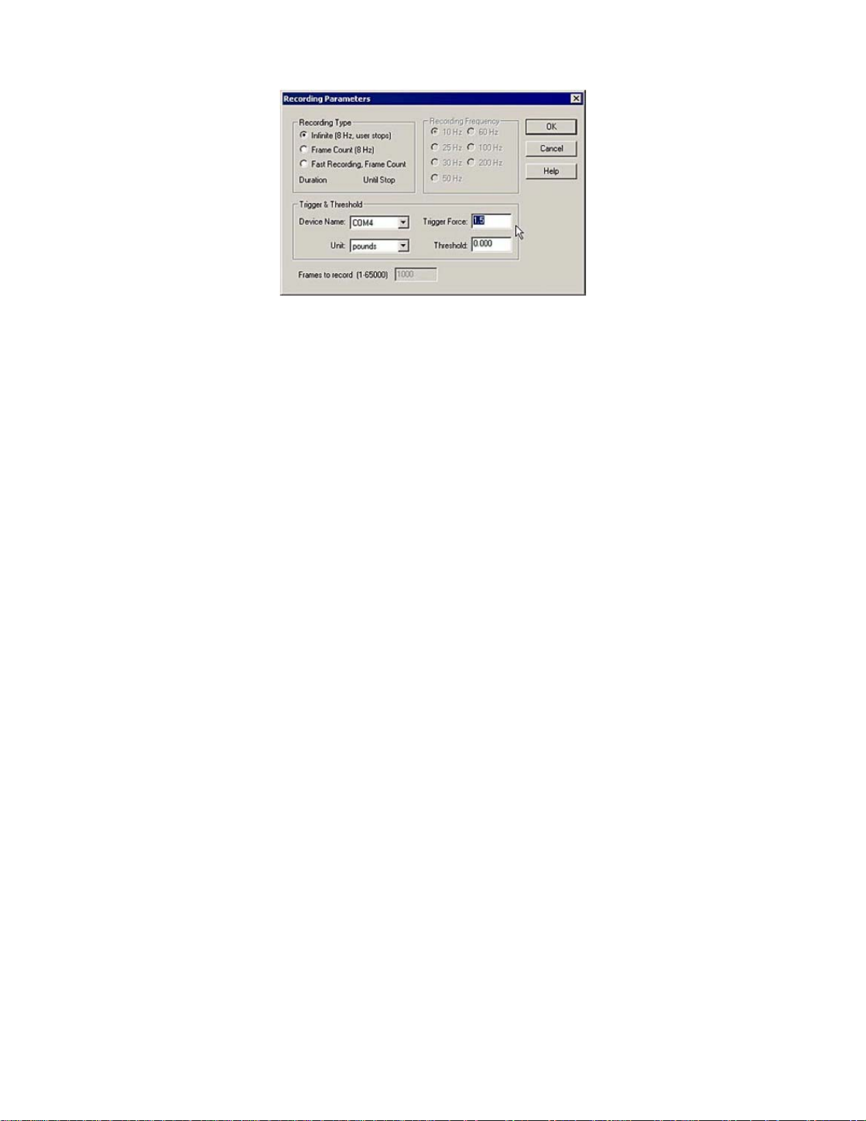
The Recording Parameters dialog box also allows you to "trigger" the start of a recording. If you enter a value in the
Trigger Force field, and select the appropriate measurement units, recording will not begin until that force is
exerted on the sensor. Enter a zero in this field to disable "triggering". Only one Trigger Force value may be
entered, and will apply to all sensors being used for testing.
The Threshold may be set for each individual COM port, so that each sensor has a different threshold. This may
be used in combination with the Trigger Force value to begin recording when force is exerted on a specific sensor.
Note: If no calibration has been performed, the only available units will be shown as a Percentage. If a
calibration has been performed, you may select from a number of force units.
CF10 21 03/03/04 REVC
Page 25

ELF Hi-Speed Recording Parameters
If you have purchased the ELF Hi-Speed system, the software will record at a higher range of speeds (up to 5760
Hz) , and your Recording Parameters dialog box will look slightly different. Your choices for Recording Type include
Infinite, Frame Count, and High Speed.
4.4.6 Tools Menu
Tools Menu when focus is on a Real-time Window:
Calibrate: Opens the ELF Calibration dialog box, which enables you to calibrate the sensor and adjust the system
sensitivity. Refer to the Calibration section for the complete calibration procedure and a thorough description of the
process.
Tools Menu when focus is on a Movie Window:
CF10 22 03/03/04 REVC
Page 26

In the Calibration dialog box, the calibration load is entered under Cal Force by typing in the value, and selecting
the appropriate units (Grams, Kilograms, Newtons, Pounds). Clicking the OK button will then begin the calibration
process. The resulting calibration can be saved as a file by selecting Save Calibration under the same Tools
menu.
If you wish to recalibrate the sensor during the same testing session, you may either select File -> New to get a
new Real-time Window, or select Tools -> Uncalibrate to reset the calibration of the current window. The current
calibration will be saved between sessions, unless Uncalibrate is selected. A dialog prompt will open asking if you
are sure you want to uncalibrate. It is usually a good idea to save your calibration file before you uncalibrate, as
there is no way to retrieve your calibration once you use this command and click OK in the message prompt below.
Sensitivity (or "Adjustable Gain") is also adjusted in the Calibration dialog box. The Sensitivity should be adjusted
whenever necessary to keep the force display in a usable range. Sensitivity settings are saved between sessions,
and are included with calibration files. The sensitivity adjustment is described in detail in the Calibration Procedure.
CF10 23 03/03/04 REVC
Page 27

Uncalibrate: This option removes the sensor’s calibration data. When this item is selected, a dialog box will
appear, giving the option of canceling the Uncalibrate operation. Uncalibrate does not affect the Sensitivity setting.
Load Calibration: allows you to use the calibration data from a previously-saved file for your current Real-time
Window. When this item is selected, an Open dialog box appears, and the calibration file can be located and
opened. Only ELF calibration files (extension *.clb) can be loaded. The Sensitivity setting that was saved with the
calibration file will also be loaded.
Save Calibration: allows you to save your current calibration as a file for future use. When this item is selected, a
Save As dialog box appears, and the calibration file can be saved with the specific file name and location of your
choice. Calibration files must have the extension *.clb, and can contain up to eight characters. The Sensitivity
setting is also saved by the calibration file.
CF10 24 03/03/04 REVC
Page 28

Select Colors: allows you to customize the background color, as well as the trace color for each ELF device in
your View windows. When this item is selected, the "Select Graph Colors" dialog box appears. By clicking on either
Trace Color or Background Color, an MS Windows color palette becomes available, and you can select one of
the standard colors or create your own custom color for each of the COM ports (sensors). The color you choose will
be used for all Movie and Real-time Windows, and will be set as the default color. To restore the original color,
select the Default All Colors button.
Change Unit: This feature allows you to quickly change the force units displayed in all windows. To use this
feature, however, you must have performed a calibration. Otherwise, all force will be displayed as "raw values".
CF10 25 03/03/04 REVC
Page 29

Change Sensitivity: This feature opens the Change Sensitivity Dialog box (below). You may adjust the sensitivity
for each sensor/COM port. Use the drop down Select Buttons field to select the COM port. Then drag the slider up
and down until you are satisfied. Adjust as many buttons as you like. When you are satisfied, click OK. To return
the system to the original sensitivity settings, click the Default button.
When you change the Sensitivity, a message will open up explaining that your calibration will be discarded (if you
have Calibrated the sensor). If you want to continue, click Yes.
You then have the option to change the Sensitivity of the sensor.
Zeroing Preload: This feature modifies the calibrated data to correct for residual pressure (referred to as the
"Offset Load") on the sensor at zero load. This operation is useful if the sensor is under some load for the entire
duration of the recording, or if the sensor must be secured in place by hardware which would cause load to be
detected by the sensor. The raw data is not affected by the Zeroing Preload function, but an extra calculation is
performed when converting the raw data to calibrated data. If the sensel is reading raw pressure, it is set at zero
raw before the calibration scale factor is applied. Zeroing Preload is recommended only for single point calibration
and may increase error when using a multi-point calibration.
4.4.7 Window Menu
Window Menu (same when focus is on either a Real-time or Movie Window):
New Window: opens a copy of the currently active Real-time or Movie Window. A number will be added to the title
of the new window, to show that it is a copy. For example, if Movie1.flf is open, and the New Window menu item is
selected, the new window’s title bar would read "Movie1.flf:2." This menu item is especially useful for opening
multiple copies of a Movie window, so you can play them back individually, or with different view properties. Copies
of Real-time Windows will display the sensor data in unison with the original window.
Cascade: arranges multiple windows in an overlapped fashion.
Tile: arranges multiple windows in an overlapped fashion, either vertically or horizontally.
Arrange Icons: arranges the icons for minimized windows at the bottom of the main window.
4.4.8 Frames Displayed Menu
Help Menu (only available when focus is on a Movie Window):
CF10 26 03/03/04 REVC
Page 30

The Frames Displayed Menu provides various display options for the amount of frames shown within the Movie
Window (along the X-axis). In addition, you can opt to view the Entire Movie within the window’s display area.
The following image shows 50 frames within a movie:
The following image shows the same movie, but this time with the Entire Movie option selected:
4.4.9 Help Menu
Help Menu (same when focus is on either a Real-time or Movie Window):
Help Topics: opens the help file associated with the Multi-Channel ELF software.
About ELF: opens the About ELF dialog box, which displays the software and hardware (device) version numbers
for your ELF system, and gives you information on how to contact Tekscan (shown below).
CF10 27 03/03/04 REVC
Page 31

5.0 SENSOR LOADING CONSIDERATIONS
The following general sensor loading guidelines can be applied to most applications, and will help you achieve the
most accurate results from your tests. It is important that you read the Sensor Performance Characteristics
section for further information on how to get the most accurate results from your sensor readings.
5.1 SENSOR LOADING
The entire sensing area of the FlexiForce sensor is treated as a single contact point. For this reason, the applied
load should be distributed evenly across the sensing area to ensure accurate and repeatable force readings.
Readings may vary slightly if the load distribution changes over the sensing area.
Note that the sensing area is the silver circle on the top of the sensor only.
It is also important that the sensor be loaded consistently, or in the same way each time. If the footprint of the
applied load is smaller than the sensing area, the load should not be placed near the edges of the sensing area, to
ensure an even load distribution. It is also important to ensure that the sensing area is the entire load path, and that
the load is not supported by the area outside of the sensing area.
If the footprint of the applied load is larger than the sensing area, it may be necessary to use a "puck". A puck is a
piece of rigid material (smaller than the sensing area) that is placed on the sensing area to ensure that the entire
load path goes through this area. The puck must not touch any of the edges of the sensing area, or these edges
may support some of the load and give an erroneous reading.
The FlexiForce sensor reads forces that are perpendicular to the sensor plane. Applications that impart "shear"
forces could reduce the life of the sensor. If the application will place a "shear" force on the sensor, it should be
protected by covering it with a more resilient material.
If it is necessary to mount the sensor to a surface, it is recommended that you use tape, when possible. Adhesives
may also be used, but make sure that the adhesive will not degrade the substrate (polyester) material of the sensor
before using it in an application. Adhesives should not be applied to the sensing area; however, if it is necessary,
ensure that the adhesive is spread evenly. Otherwise, any high spots may appear as load on the sensor.
5.2 SATURATION
The Saturation force is the point at which device output no longer varies with applied force. The saturation force of
each sensor is based on the maximum recommended force specified by Cooper Instruments, which is printed on
system packaging or the actual sensor, along with the "Sensitivity".
Sensors are available in three force ranges (Low, Medium, and High), which have specified maximum forces of
25, 150, and 1000 lbf, respectively. The sensor’s effective force range (up to the specified maximum) can be
altered by adjusting the system sensitivity (refer to the Calibration section). Decreasing the sensitivity setting (1 to
20 possible) will increase the force range (displayed as "Approx Max Range"), and "saturation" force, of the sensor,
and vice versa.
CF10 28 03/03/04 REVC
Page 32

It is essential that the sensor(s) do not become saturated during testing.
5.3 CONDITIONING SENSORS
Exercising, or Conditioning a sensor before calibration and testing is essential in achieving accurate results from
your ELF system. It helps to lessen the effects of drift and hysteresis. Conditioning is required for new sensors, and
for sensors that have not been used for a length of time.
To condition a sensor, place 110% of the test weight on the sensor, allow the sensor to stabilize, and then remove
the weight. Repeat this process four or five times. The interface between the sensor and the test subject material
should be the same during conditioning as during calibration
IMPORTANT! Sensors must be properly conditioned prior to calibration and use.
and actual testing.
6.0 CALIBRATION
The ELF system sensor acts as a variable resistor in a circuit. This circuit produces a digital output value (between
0-100%) based on the sensor resistance and the system handle.s adjustable gain (sensitivity). Calibration is the
method by which this digital output is related to an actual engineering unit, such as pounds or Newtons. If you are
using the Multi-Handle ELF system, all selected COM ports must be calibrated with at least one point before
Calibration can be completed.
To calibrate, apply a known force to the sensor. The software then equates this applied force to the digital output
that it reads, and performs a linear interpolation between zero load and the known calibration load. In this way, the
software determines the actual force range that matches the digital output range of 0-100%.
To perform a multi-point calibration, apply at least two known forces to a sensor. The software then equates this
applied force to the digital output that it reads, and performs one of two types of interpolation between zero load
and the known calibration loads. In this way, the software determines the actual force range that matches the digital
output range of 0-100%.
• Best Fit Linear Calibration: This calibration creates a best-fit curve through two known force values. After a
known load is added as a calibration point, select the Params button for details about the calibration, including
slope, offset and Correlation Coefficient (r2).
• Piece Wise Linear Calibration: This calibration connects each calibration point directly and interpolates between
the values.
CF10 29 03/03/04 REVC
Page 33

NOTE: if you have a Multi-Handle ELF system, all handles must use the same type of calibration. Linear
and Best Fit cannot be mixed and matched.
The "Sensitivity" (or "Adjustable Gain") is also adjusted in the ELF Calibration dialog box. This adjustment sets the
data output range from the computer (0 to 100%) to the actual force range output from the system handle. In this
way, the usable force range of the sensor can be adjusted (up to the rated maximum force). "Sensitivity" settings
are saved between sessions, and are included with calibration files.
6.1 CALIBRATION GUIDELINES
The following guidelines should be considered when calibrating a sensor:
• Apply a calibration load that approximates the load to be applied during system use, using dead weights or a
testing device (such as an MTS or Instron). If you intend to use a "puck" during testing, also use it when
calibrating the sensor. See Sensor Loading Considerations for more information on using a puck.
• Avoid loading the sensor to near saturation when calibrating. If the sensor saturates at a lower load than desired,
adjust the "Sensitivity".
• Distribute the applied load evenly across the sensing area to ensure accurate force readings. Readings may vary
slightly if the load distribution changes over the sensing area.
Note: Read the Sensor Performance Characteristics section before performing a Calibration.
CF10 30 03/03/04 REVC
Page 34

6.2 CALIBRATION PROCEDURE
IMPORTANT! Sensors must be properly conditioned prior to calibration and use.
1. Select File -> New to open a new Real-time window. If you wish to use a previously saved calibration file,
select Tools -> Load Calibration, enter the calibration file name and path, and click OK.
2. Load each sensor with a known force.
3. Click Tools -> Change Sensitivity. If you have the Multi-Handle ELF system, adjust sensitivity for each
sensor, if necessary, by either dragging the slider up and down, or entering an integer between 1 and 20
(default is 12). The "Sensitivity" should be adjusted whenever necessary to keep the force display in a usable
range.
4. Click on Tools -> Calibrate. This brings up the Calibration dialog box.
5. Select Best Fit Linear calibration or Piece Wise Linear calibration.
CF10 31 03/03/04 REVC
Page 35

6. Select the Port/Device you wish to calibrate first. If you have the Multi-Handle ELF system, all Port/Devices
must be calibrated before you may select Finish.
CF10 32 03/03/04 REVC
Page 36

7. Select the appropriate Force unit from the drop-down box (grams, kilograms, Newtons, pounds).
8. Load the sensor with a known force. The key to an accurate calibration is applying a stable load. Enter the
known load in the Cal Force field. If the applied force is not stable, an error message will appear which requires
you to either accept or cancel the current calibration.
It is recommended that you stabilize the force; otherwise, your calibration may be inaccurate. In the example
below, we have loaded the sensor with a 1-pound weight at 20%.
9. Click Add Point. A point will appear in the Multipoint Calibration box (shown above).
CF10 33 03/03/04 REVC
Page 37

10. Repeat the steps with as many known loads as you wish.
11. If you wish to discard any points, click to highlight them in the Force/Raw column. Then select Remove Point.
12. If you have the Multi-Handle ELF system, continue selecting Port/Devices and adding as many known loads as
you wish, until at least one calibration point has been added for each sensor.
13. Once all Calibration points have been added for all Ports/Devices, click Finish. The Real-time window will now
display force in units of force rather than raw force.
CF10 34 03/03/04 REVC
Page 38

14. If you wish to save the calibration file for future use, select Tools -> Save Calibration, and enter the desired
destination and file name in the Save As dialog box. Calibration files must be saved with the *.clb file
extension. Sensitivity settings are saved with calibration files.
15. If you wish to recalibrate the sensor during the same testing session, you may either select File -> New to get a
new Real-time Window, or select Tools -> Uncalibrate to reset the calibration of the current window. A
calibration will be saved between sessions unless Uncalibrate is selected.
7.0 SENSOR PERFORMANCE CHARACTERISTICS
There are a number of characteristics of sensors, which can affect your results. This section contains a description
of each of these conditions, and recommendations on how to lessen their effects.
7.1 REPEATABILITY
Repeatability is the ability of the sensor to respond in the same way to a repeatedly applied force. As with most
measurement devices, it is customary to exercise, or "condition" a sensor before calibrating it or using it for
measurement. This is done to reduce the amount of change in the sensor response due to repeated loading and
unloading. FlexiForce sensors are generally repeatable within 2.5% once they have been conditioned. A sensor is
conditioned by loading it to 110% of the test weight four or five times. Follow the full procedure in the Conditioning
Sensors section.
7.2 LINEARITY
Linearity refers to the sensor.s response (digital output) to the applied load, over the range of the sensor. This
response should ideally be linear; and any non-linearity of the sensor is the amount that its output deviates from
this line. A calibration is performed to "linearize" this output as much as possible. FlexiForce sensors are linear
within +/- 5%.
CF10 35 03/03/04 REVC
Page 39

7.3 HYSTERESIS
Hysteresis is the difference in the sensor output response during loading and unloading, at the same force. For
static forces, and applications in which force is only increased, and not decreased, the effects of hysteresis are
minimal. If an application includes load decreases, as well as increases, there may be error introduced by
hysteresis that is not accounted for by calibration. For a conditioned sensor, with 50% of the full force range
applied, hysteresis is less than 4.5 % of full scale.
7.4 DRIFT
Drift is the change in sensor output when a constant force is applied over a period of time. If the sensor is kept
under a constant load, the resistance of the sensor will continually decrease, and the output will gradually increase.
It is important to take drift into account when calibrating the sensor, so that its effects can be minimized. The
simplest way to accomplish this is to perform the sensor calibration in a time frame similar to that which will be used
in the application. In FlexiForce sensors, drift is less than 3%/logarithmic time.
7.5 TEMPERATURE SENSITIVITY
The operating range for FlexiForce sensors is from 15°F (-9°C) to 140°F (60°C). FlexiForce sensor output may
vary up to 0.2% per degree F (approx. 0.36% per degree Celsius). In general, your results will vary if you combine
high loads on the sensor with high temperatures. For loads of less than 10 lbs., the operating temperature can be
increased to 165°F (74°C).
To ensure accuracy, calibrate the sensor at the temperature at which it will be used in the application. If the sensor
is being used at different temperatures, perform a calibration at each of these temperatures, save the calibration
files, then load the appropriate calibration file when using the sensor at that temperature.
FlexiForce sensors should be stored at temperatures in the range of 15°F (-9°C) to 165°F (74°C).
7.6 SENSOR LIFE / DURABILITY
Sensor life depends on the application in which it is used. Sensors are reusable, unless used in applications in
which they are subjected to severe conditions, such as against sharp edges, or shear forces. FlexiForce sensors
have been successfully tested at over one million load cycles using a 50 lb. force.
Rough handling of a sensor will also shorten its useful life. For example, a sensor that is repeatedly installed in a
flanged joint will have a shorter life than a sensor installed in the same joint once and used to monitor loads over a
prolonged period. After each installation, visually inspect your sensors for physical damage.
It is also important to keep the sensing area of the sensor clean. Any deposits on this area will create uneven
loading, and will cause saturation to occur at lower applied forces.
8.0 USING THE ELF LABVIEW VI’S
Here you will find information about the ELF LabVIEW VI’s. VI’s are Virtual Instruments that can be used to aid you
in providing important data on your computer. For further information about LabVIEW, consult the documentation
that came with your LabVIEW purchase.
8.1 LABVIEW VI INSTALLATION
Copy the Tksn-ELF.llb file onto your computer. This file contains all of the VI.s used with Tekscan.s ELF.
To use the VI.s, open the Tksn-ELF.llb from LabVIEW and select the desired VI. Details about each individual VI
are listed later. The selected VI will usually be added into a VI created by the user, though the .Getting Started. VI
can be used directly.
8.2 VI’S
All ELF VI.s include "Error In" and "Error Out" connectors. This allows errors generated early in the VI sequence to
stop processing in later VI.s. They also force data dependencies that force VI.s to be executed in a specific order.
CF10 36 03/03/04 REVC
Page 40

8.2.1 VISA Sessions
If you use the separate VI.s instead of the Getting Started VI, you must manage the VISA session used to
communicate to the sensor. Create one VISA session for each sensor used (e.g. one session for COM1, another
session for COM2 if used) by using the Initialize VI and passing it the serial port number. Pass the created VISA
session to other VI.s such as Sensitivity VI and Read VI. You must eventually close all open VISA sessions by
sending the session to the Close VI.
8.2.2 Getting Started VI
This is the easiest VI to use, since it is completely self-contained. However, for multiple readings, it is slower than
using the separate Initialize, Read and Close UI’s.
• Serial Port: varies from 1 to the number of serial ports on your system. 1 = COM1, 2 = COM2 etc. The serial
ports defaults to 1 if not connected.
• Error In: is a standard error structure. If not connected a default structure, set to no error, is used. If Error In
indicates a previous error, the VI provides no output and passes the error unmodified to Error Out.
• Data Read: is an integer (U8), which is the pressure reading from the sensor. It can vary from 0 to 255. If either
an error occurs internally, or an error is indicated on Error In, no output is produced.
• Error Out: sends errors to the next VI. This error can either be an error duplicated from Error In, or an error
produced in the VI itself.
One data reading is produced for each invocation of the VI. The serial port is opened and closed with each
invocation, making it slower than the Read VI (which requires an already opened VISA session).
When viewed as a panel, it shows a strip chart of the current and previous readings.
8.2.3 Tekscan-ELF App Example
This VI shows an example ELF application. This VI requires an open VISA session (which is supplied by the
Initialize VI). The VISA session must eventually be closed, by sending it to the Close VI.
This VI shows using the ELF with sensitivity adjustment and scaling the output value (calibration).
• VISA Session: Represents an open serial port. This must originate from the Initialize VI.
• Sensitivity: Adjusts the sensitivity of the sensor. It can vary from 1 to 20, with the default being 10.
• Full Scale Value: Is the calibrated reading which is displayed when the sensor outputs full scale (255 raw).
• Error In: is a standard error structure. If not connected a default structure, set to no error, is used. If Error In
indicates a previous error, the VI provides no output and passes the error unmodified to Error Out.
• Data Read: is an integer (U8) which is the pressure reading from the sensor. It can vary from 0 to 255. If either
an error occurs internally, or an error is indicated on Error In, no output is produced.
• Error Out: sends errors to the next VI. This error can either be an error duplicated from Error In, or an error
produced in the VI itself.
8.2.4 Tekscan-ELF Loop Example
CF10 37 03/03/04 REVC
Page 41

This example VI is similar to Tekscan-ELF App Example, except that it manages the VISA session internally. There
is a switch on the soft panel that indicates whether to continue reading the sensor or to stop. Set the switch on and
run the VI. The VI will continually read the sensor until the switch is set off.
The inputs and outputs have the same meanings as for the Tekscan-ELF App Example
8.2.5 Initialize
The Initialize VI opens the selected serial port and produces a VISA session that can be passed to other ELF VI.s.
The VISA session must eventually be sent to the Close VI to close the serial port.
• Serial Port: varies from 1 to the number of serial ports on your system. 1 = COM1, 2 = COM2 etc. The serial
ports defaults to 1 if not connected.
• Error In: is a standard error structure. If not connected a default structure, set to no error, is used. If Error In
indicates a previous error, the VI provides no output and passes the error unmodified to Error Out.
• VISA Session: Represents an open serial port. This may be passed to other VI.s, but must be sent to the Close
VI when complete.
• Error Out: sends errors to the next VI. This error can either be an error duplicated from Error In, or an error
produced in the VI itself.
8.2.6 Close
The Close VI closes the given VISA session (thereby closing the serial port). All VISA sessions opened by the
Initialize VI must be closed by the Close VI when processing is complete.
• Error In: is a standard error structure. If not connected a default structure, set to no error, is used. If Error In
indicates a previous error, the VI provides no output and passes the error unmodified to Error Out.
• VISA Session: Represents an open serial port. This session is closed when the VI runs.
• Error Out: sends errors to the next VI. This error can either be an error duplicated from Error In, or an error
produced in the VI itself.
8.2.7 Sensitivity
This VI sets the sensitivity of the ELF sensor. The sensitivity can vary from 1 to 20, with the default at 10. A higher
sensitivity produces a higher reading for the same force. The sensitivity stays in place until the VISA session is
closed.
• VISA Session Represents an open serial port. This must originate from the Initialize VI.
• Sensitivity Adjusts the sensitivity of the sensor. It can vary from 1 to 20, with the default being 10.
CF10 38 03/03/04 REVC
Page 42

• Error In is a standard error structure. If not connected a default structure, set to no error, is used. If Error In
indicates a previous error, the VI provides no output and passes the error unmodified to Error Out.
• VISA Session Out Represents an open serial port. This may be passed to other VI.s, but must be sent to the
Close VI when complete.
• Error Out sends errors to the next VI. This error can either be an error duplicated from Error In, or an error
produced in the VI itself.
8.2.8 Read
This VI gets a single reading from the sensor. The reading is a single byte (0 . 255).
• VISA Session Represents an open serial port. This must originate from the Initialize VI.
• Error In: is a standard error structure. If not connected a default structure, set to no error, is used. If Error In
indicates a previous error, the VI provides no output and passes the error unmodified to Error Out.
• VISA Session Out: Represents an open serial port. This may be passed to other VI’s, but must be sent to the
Close VI when complete.
• Data Read: is an integer (U8) which is the pressure reading from the sensor. It can vary from 0 to 255. If either
an error occurs internally, or an error is indicated on Error In, no output is produced.
• Error Out: sends errors to the next VI. This error can either be an error duplicated from Error In, or an error
produced in the VI itself.
GLOSSARY
A
About Elf (Help Menu): The "About Elf" command displays a dialog window with information about the software
version, as well as contact information for Tekscan.
Adjustable Gain: See "Sensitivity".
Arrange Icons (Window Menu): The "Arrange Icons" arranges the icons for minimized windows at the bottom of
the main window.
B
Best Fit Linear Calibration: This calibration creates a best-fit curve through two known force values. After a
known load is added as a calibration point, select the "Params" button from the Calibration dialog for details
about the calibration, including slope, offset and Correlation Coefficient (r2).
C
Cal Force: A value that is entered by the user on the Calibration dialog box. This value is the calibration load that is
placed on the sensor in order to convert the Digital output into Engineering Units.
Calibrate (Tools Menu): The "Calibrate" command opens the ‘ELF Calibration’ dialog box, which enables you to
calibrate the sensor and adjust the system sensitivity. See "Calibration".
Calibration: Calibration is the method by which this digital output of the sensor is related to an actual engineering
unit, such as pounds or Newtons. If you are using the Multi-Handle ELF system, all selected COM ports must
be calibrated with at least one point before Calibration can be completed.
Cascade (Window Menu): The "Cascade" command arranges multiple windows in an overlapped fashion.
Change Sensitivity (Tools Menu): The "Change Sensitivity" command opens the Sensitivity Dialog box. You may
adjust the sensitivity for each sensor/COM port. Use the drop down Select Buttons field to select the COM port.
Then drag the slider up and down until you are satisfied. Adjust as many buttons as you like. When you are
satisfied, click OK. To return the system to the original sensitivity settings, click the Default button. See
"Sensitivity".
Change Unit (Tools Menu): The "Change Unit" command allows you to quickly change the force units displayed in
CF10 39 03/03/04 REVC
Page 43

all windows. To use this feature, however, you must have performed a calibration. Otherwise, all force will be
displayed as raw values.
Close (File Menu): The "Close" command causes the currently active Real-time or Movie window to close. If a
movie has been recorded, but not saved, the software gives the option of saving the movie file.
Column (View Menu): The "Column" option displays each COM port individually, with force value displayed on the
Y-Axis. Each column is color-coded to indicate the individual COM ports. As time elapses, the columns indicate
changes in force.
COM Port: The hardware which connects the sensor to your computer. Each sensor is designated a COM Port on
your PC. When you open a new Real-Time Window, you must select the Ports that are to be displayed in your
Real-Time Window (such as COM 4, COM 5, etc.)
Conditioning: Exercising the sensor prior to Calibration and use. To ensure the most accurate results, it is always
recommended to condition the sensor by placing 110% of the test weight on the sensor, allowing it to stabilize,
and then removing the weight. This process should then be repeated four or five times. Conditioning your
sensors helps lessen the effects of "Drift" and "Hysteresis", and is required for new sensors or sensors that
have not been used for a length of time.
Copy (Edit Menu): The "Copy" command saves the current Real-time or Movie frame to the MS Windows
clipboard. This data is saved in the clipboard as a graphic (bitmap) image of the current window. Once copied
to the clipboard, this data can be pasted into other Windows applications by selecting Edit>>Paste.
D
Drift: Drift is the change in sensor output when a constant force is applied over a period of time. If the sensor is
kept under a constant load, the resistance of the sensor will continually decrease, and the output will gradually
increase. It is important to take Drift into account when calibrating the sensor, so that its effects can be
minimized. The simplest way to accomplish this is to perform the sensor calibration in a time frame similar to
that which will be used in the application. In FlexiForce sensors, drift is less than 3%/logarithmic time.
Duration: Refers to a setting within the Recording Parameters dialog box. The Duration is listed below the
.Recording Type.; it will either say ‘Until Stop’ if Infinite is selected, or the approximate duration (in seconds) the
recording will take to complete if Frame Count is specified. See "Recording Parameters".
E
ELF Hardware: The ELF hardware consists of the sensor handle(s), ELF software, and the SSB-F (Single Sensing
Button - Flexiforce) sensors.
ELF Software: The ELF software is a 32-bit application that is compatible with Microsoft (MS) Windows 95/98 and
NT. The software allows you to view a graphical representation of the force on the sensor in real time, record
this information as a ‘movie’, and review and analyze it later. There are a number of options for displaying the
Real-time force data; it can be displayed as a strip chart, meter, column graph, or digital readout. Recorded
‘movie’ frames can be saved as ASCII (text) files, which can be imported into a spreadsheet program, or
opened in a text editor or word processing program. Real-time data or movie frames can also be copied to the
Windows clipboard and pasted into other applications as a ".bmp" (bitmap) file.
F
Fast Recording: Refers to one of the Recording Parameter options. When Fast Recording is selected, the ‘Frames
to Record’ may be entered, and the Recording Frequency (Hz) may be selected to the right. In Fast Recording
applications, recordings can be obtained at frequencies of 10, 25, 30, 50, 60, 100, and 200 Hz. See "Recording
Parameters".
First Frame (Movie Toolbar Playback Controls): Positions the recording at the beginning (First Frame).
Focus: The currently selected Window within your ELF software. Only one window can be selected at a time. A
window is selected by clicking on it, and when selected, the title bar will turn blue. When a window is selected in
this manner, it is said to have "focus".
Frame Count: Refers to one of the Recording Parameter options. When selected, the number of Frames to Record
may be entered at the bottom of the dialog box. The recording will stop when this number of frames has been
recorded, regardless of the duration of the movie. See "Recording Parameters".
Frames Displayed: A submenu of the Main Menu. The Frames Displayed Menu provides various display options
for the amount of frames shown within the Movie Window (along the X-axis). In addition, you can opt to view
the "Entire Movie" within the window’s display area.
CF10 40 03/03/04 REVC
Page 44

H
Handle: The handle is a piece of hardware that gathers data from the sensor, processes it, and sends it to your
computer through a serial port (COM Port). See "ELF Hardware" and "COM Port".
Help Topics (Help Menu): The "Help Topics" command opens the help file associated with the Multi-Channel ELF
software. About ELF opens the About ELF dialog box, which displays the software and hardware (device)
version numbers for your ELF system, and gives you information on how to contact FlexiForce
Hi-Speed Recording Parameters: Refers to the options available under the Recording Parameters dialog box. If
you have purchased the ELF Hi-Speed system, the software will record at a higher range of speeds, and your
Recording Parameters dialog box will look slightly different. Your choices for Recording Type include Infinite,
Frame Count, and High Speed. See "Recording Parameters".
Hysteresis: Hysteresis is the difference in the sensor output response during loading and unloading, at the same
force. For static forces, and applications in which force is only increased, and not decreased, the effects of
hysteresis are minimal. If an application includes load decreases, as well as increases, there may be error
introduced by hysteresis that is not accounted for by calibration. For a conditioned sensor, with 50% of the full
force range applied, hysteresis is less than 4.5 % of full scale.
I
Increase / Decrease Decimal: Two icons on the Tool Bar do not have corresponding pull-down menus. They are
the Increase Decimal and Decrease Decimal buttons. When sensors have been calibrated, units of force will be
shown. Clicking these buttons will either increase or decrease the number of decimal places displayed by the
software.
L
Last Frame (Movie Toolbar Playback Controls): Positions the recording at the end of the movie (last frame).
Linearity: Linearity refers to the sensor’s response (digital output) to the applied load, over the range of the sensor.
This response should ideally be linear; and any non-linearity of the sensor is the amount that its output deviates
from this line. A calibration is performed to ‘linearize’ this output as much as possible. FlexiForce sensors are
linear within +/- 5%.
Load Calibration (Tools Menu): The "Load Calibration" command allows you to use the calibration data from a
previously-saved file for your current Real-time window. When this item is selected, an ‘Open’ dialog box
appears, and the calibration file can be located and opened. Only ELF calibration files (extension *.clb) can be
loaded. The Sensitivity setting that was saved with the calibration file will also be loaded.
M
Main Menu: The Main Menu contains important commands you use to perform functions within the software. Some
menu commands can be found directly in the toolbar, however, not all commands found under the menu are
located on the toolbar. The Main Menu changes, depending where your focus lies. The reason for this
difference is because there are some commands that can only be accessed from a Movie Window, and others
from a Real-Time Window. For example, if you have two windows open, one a Real-Time Window, and the
other a Movie Window, the Main Menu will contain a different set of submenus and commands.
Main Window: When you initiate the ELF software program, the Main Window is displayed on your computer
screen. The Main Window consists of the Menu Bar, Tool Bar, and Main Status Bar, and may contain one or
more Real-time or Movie Windows. The window that is selected is considered the active window or the window
that has focus. See "Focus". Only one window can be active at one time, and the title bars of the other windows
will be grayed out.
Menu Bar: The Menu Bar provides drop-down menus (submenus) used to control the ELF software program. It is
located at the top of the Main Window.
Minimum Requirements: The minimum hardware requirements that your computer must meet in order to run the
ELF software and operate the hardware successfully. The minimum requirements are: Pentium 300 MHz with
64 MB RAM and 5 MB of Hard Drive Space. In addition, a 3 ½ Inch Floppy Drive or CD Drive, One 9-pin RS232 port per ELF handle, and Windows Operating System (one of the following: 95 / 98 / ME / NT / 2000 / XP).
See "Hardware".
Movie Toolbar (Playback Controls): This bar is located at the top of the Movie Window, and consists of the movie
playback icons and the Save As icon. See "Playback Controls".
Movie Window: The Movie Window displays a previously recorded movie. It consists of the display area, scroll bar,
the "Movie Toolbar (with playback controls) and the "Movie Window Status Bar".
CF10 41 03/03/04 REVC
Page 45

Multi-Point Calibration: Multi-Point Calibration is a method in which at least two known forces are applied to the
sensor and then calculated to convert Digital Output into Engineering Units. See "Calibration".
N
New (File Menu): The "New" command opens a new Real-time window, in addition to any other Real-time or Movie
windows that are currently open. The new Real-time window becomes the active window when it is opened. If
more than one Real-time window is open, the force data will be displayed in all windows, in unison. If the
sensor has already been calibrated, this calibration will also apply to the new Real-time window.
Next Frame (Movie Toolbar Playback Controls): Plays the recording forward one frame each time it is clicked.
Number (View Menu): The "Number" option displays each COM port as numerical values. Each numerical value is
color coded to indicate the individual COM ports. As time elapses, the numbers change to indicate changes in
force.
O
Open (File Menu): The "Open" command displays the Open dialog box, which allows you to open previously
recorded movie files. Only ELF movie files, with the *.flf file extension, can be opened.
P
Piece Wise Linear Calibration: This calibration connects each calibration point directly and interpolates between
the values.
Play Backward (Movie Toolbar Playback Controls): Plays the recording in reverse.
Play Forward (Movie Toolbar Playback Controls): Plays the recording forward.
Playback Controls: The Playback controls are used for movie playback functions. The following functions are
available: "First Frame", "Play Backward", "Previous Frame", "Stop", "Next Frame", "Play Forward", and "Last
Frame". See "Movie Toolbar (Playback Controls)".
Port: See "COM Port".
Previous Frame (Movie Toolbar Playback Controls): Plays the recording in reverse one frame each time it is
clicked.
Properties (View Menu): The "Properties" command opens the Properties dialog box, which allows you to change
how the data is displayed on the screen. Any changes made to the Properties will only affect the currently
active Real-time or Movie window. The Properties dialog box will also appear whenever you click the right
mouse button over a Real-Time or Movie Window. You can select a display option ("Strip Chart", "Column" or
"Number"), and also change the "Scale Max", "Scale Min", and "Units".
R
Real-Time Window: A Real-time Window displays the load applied to the sensor as it is happening (in Real-time).
The Properties of this display can be changed in the File pull-down menu, or by clicking the right mouse button.
Recording Parameters: The recording parameters act as settings for your Movie. Before you record a movie, you
should access the Recording Parameters dialog box by going into Record -> Settings. Within this dialog box
you can select what type of recording you are going to create. Things that can be selected are the amount of
frames, speed of recording, any triggering options that need to occur before the recording starts, Which sensor
will trigger the recording, and the type of units (Pounds, Newtons, Kilograms, etc.).
Repeatability: Repeatability is the ability of the sensor to respond in the same way to a repeatedly applied force.
As with most measurement devices, it is customary to exercise, or .condition. a sensor before calibrating it or
using it for measurement. This is done to reduce the amount of change in the sensor response due to repeated
loading and unloading. FlexiForce sensors are generally repeatable within 2.5% once they have been
conditioned. A sensor is conditioned by loading it to 110% of the test weight four or five times.
S
Saturation: The saturation force is the point at which the device output no longer varies with applied force. The
saturation force of each sensor is based on the maximum recommended force specified by Tekscan, which is
printed on the system packaging or the actual sensor, along with the sensitivity. Sensors are available in three
force ranges (Low, Medium, and High), which have specified maximum forces of 25, 150, and 1000 lbf,
respectively. The sensor.s effective force range (up to the specified maximum) can be altered by adjusting the
system sensitivity. Decreasing the sensitivity setting (1 to 20 possible) will increase the force range (displayed
as .Approx Max Range.), and saturation force, of the sensor, and vice versa. It is essential that the sensors do
CF10 42 03/03/04 REVC
Page 46

not become saturated during testing. See "Sensitivity" and "Calibration".
Save As (File Menu): The "Save As" command will save the current movie with the specific file name and location
of your choice. ELF movie files must have the extension *.flf. Note that your system may limit filenames to eight
characters. This menu item can be used to save a movie file under more than one filename.
Save as ASCII (File Menu): The "Save As ASCII" command saves the current Movie frame as an ASCII file, with
the extension *.csv. Since these files are in ASCII (comma separated value) format, they can be imported into a
spreadsheet program (e.g. MS Excel), or they can be opened in a text editor or word processing program (e.g.
MS Word) in order to review and manipulate the data.
Save Calibration (Tools Menu): The "Save Calibration" command allows you to save your current calibration as a
file for future use. When this item is selected, a ‘Save As’ dialog box appears, and the calibration file can be
saved with the specific file name and location of your choice. Calibration files must have the extension *.clb,
and can contain up to eight characters. The Sensitivity setting is also saved by the calibration file.
Scroll Bar (Movie Window): The Scroll bar is located directly above the status bar in a Movie Window (at the
bottom of the movie window below the force data). It can be used to move to any point (frame) in the movie.
Select Colors (Tools Menu): The "Select Colors" command allows you to customize the background color, as well
as the trace color for each ELF device in your View windows. When this item is selected, the ‘Select Graph
Colors’ dialog box appears. By clicking on either Trace Color or Background Color, a Windows color palette
becomes available, and you can select one of the standard colors or create your own custom color for each of
the COM ports (sensors). The color you choose will be used for all Movie and Real-time windows, and will be
set as the default color. To restore the original color, select the Default All Colors button.
Sensing Area: The Sensing area is the silver circle located on the top of the sensor.
Sensitivity: Also referred to as "Adjustable Gain". This adjustment sets the data output range from the computer (0
to 100%) to the actual force range output from the system handle. In this way, the usable force range of the
sensor can be adjusted (up to the rated maximum force). Sensitivity settings are saved between sessions, and
are included with calibration files. Sensitivity can be accessed directly from the Tools Menu or from within the
Calibration dialog box.
Sensor Life / Durability: Sensor life depends on the application in which it is used. Sensors are reusable, unless
used in applications in which they are subjected to severe conditions, such as against sharp edges, or shear
forces. FlexiForce sensors have been successfully tested at over one million load cycles using a 50 lb. force.
Rough handling of a sensor will also shorten its useful life. For example, a sensor that is repeatedly installed in
a flanged joint will have a shorter life than a sensor installed in the same joint once and used to monitor loads
over a prolonged period. After each installation, visually inspect your sensors for physical damage. It is also
important to keep the sensing area of the sensor clean. Any deposits on this area will create uneven loading,
and will cause saturation to occur at lower applied forces.
Sensor Temperature Sensitivity: The operating range for FlexiForce sensors is from 15°F (-9°C) to 140°F (60°C).
FlexiForce sensor output may vary up to 0.2% per degree F (approx. 0.36% per degree C). In general, your
results will vary if you combine high loads on the sensor with high temperatures. For loads of less than 10 lbs.,
the operating temperature can be increased to 165 °F (74 °C). To ensure accuracy, calibrate the sensor at the
temperature at which it will be used in the application. If the sensor is being used at different temperatures,
perform a calibration at each of these temperatures, save the calibration files, then load the appropriate
calibration file when using the sensor at that temperature. FlexiForce sensors should be stored at temperatures
in the range of 15°F (-9°C) to 165°F (74°C).
Sensors: The FlexiForce sensor is an ultra-thin (0.005.), flexible printed circuit. It is 0.55. (14 mm.) wide and 9.0.
(229 mm.) in length. Sensors are available in three full-scale force ranges: Low (25 lbf ), Medium (150 lbf ), and
High (1000 lbf ). The active sensing area is a 0.375. diameter circle at the end of the sensor. The sensors are
constructed of two layers of substrate, such as a polyester film. On each layer, a conductive material (silver) is
applied, followed by a layer of pressure-sensitive ink. Adhesive is then used to laminate the two layers of
substrate together to form the sensor. The ‘active sensing area’ is defined by the silver circle on top of the
pressure sensitive ink. Silver extends from the sensing area to the connectors at the other end of the sensor,
forming the conductive leads. The sensor acts as a variable resistor in an electrical circuit. When the sensor is
unloaded, its resistance is very high (greater than 5 Meg-ohm); when a force is applied to the sensor, the
resistance decreases. FlexiForce sensors have been successfully tested at over one million load cycles using a
50 lb. force. See also "Sensor Life / Durability".
Settings (Record Menu): Settings: brings up the Recording Parameters dialog box, which allows you to change
the current recording parameters. Under ‘Recording Type’, there are three possibilities that may be selected.
See "Recording Parameters".
Start (Record Menu): The "Start" command is used to make a recording (movie). When Start is selected, the
software begins recording a movie of the current Real-time window data using the settings that have been
CF10 43 03/03/04 REVC
Page 47

selected (see Settings menu item). When data is being recorded, the Recording In Progress message will
appear (shown below), and the Recording On icon (on the Main Tool Bar) will become active (the red circle will
become grayed out, and the square "Stop" button -- black color -- will become visible). If .Triggering. is in effect,
and Record is selected, the Waiting for Trigger message will be displayed until the trigger force is reached.
Movies created by the ELF system are stored as *.flf files.
Status Bar (Main): The Main Status Bar provides the user with feedback about what is happening inside the ELF
software. It will either say .For Help, Press F1., or will give a description of whichever Toolbar icon is under the
cursor. The Main Status Bar is located at the bottom of the Main Window.
Status Bar (Movie Window): The Movie Window Status Bar is located at the bottom of the Movie Window, and
displays the Frame count (the current frame number vs. the total number in the movie).
Status Bar (View Menu): The "Status Bar" option is used to display or hide the Movie and Main Status Bars.
These status bars can be toggled by clicking this menu item on and off. If a Real-time window is active, this
menu item affects the Main Status Bar. If a Movie window is active, this menu item affects the Movie Status
Bar.
Stop (Movie Toolbar Playback Controls): Stops playback.
Stop (Record Menu): The "Stop" command will cause the software to stop recording the active Real-time window,
even if the correct number of movie frames (as selected in Settings) have not yet been recorded.
Strip Chart (View Menu): The "Strip Chart" option is the default display mode, where force value is displayed on
the Y-Axis and elapsed time is displayed on the X-Axis.
T
Temperature Sensitivity: See "Sensor Temperature Sensitivity".
Threshold: Refers to a value within the Recording Parameters that is set by the user. The Threshold may be set
for each individual COM port, so that each sensor has a different Threshold. This may be used in combination
with the Trigger Force value to begin recording when force is exerted on a specific sensor. See "Recording
Parameters".
Tile (Window Menu): The "Tile" command arranges multiple windows in an overlapped fashion, either vertically or
horizontally.
Toolbar: The Toolbar provides some of the same options as the Menu Bar, but with icons replacing drop-down
menus. It is located directly below the Menu Bar, at the top of the Main Window. Note that not all items in the
Menu Bar have a corresponding icon on the Tool Bar.
Toolbar (View Menu): The "Tool Bar" option is used to display or hide the Movie and Main Tool Bars. These tool
bars can be toggled by clicking this menu item on and off. If a Real-time window is active, this menu item
affects the Main Tool Bar. If a Movie window is active, this menu item affects the Movie Tool Bar.
Trigger Force: See "Triggering".
Triggering: Refers to the Recording Parameters dialog box. This dialog box allows you to .trigger. the start of a
recording based on a force value. If you enter a value in the .Trigger Force. field, and select the appropriate
measurement units, recording will not begin until that force is exerted on the sensor. Enter a zero in this field to
disable .triggering.. Only one Trigger Force value may be entered, and will apply to all sensors being used for
testing. See "Recording Parameters".
U
Uncalibrate (Tools Menu): The "Uncalibrate" command removes the sensor’s calibration data. When this item is
selected, a dialog box will appear, giving the option of canceling the Uncalibrate operation. Uncalibrate does
not affect the Sensitivity setting. See "Sensitivity".
V
VI: Virtual Instrumentation
Z
Zeroing Preload (Tools Menu): The "Zeroing Preload" command modifies the calibrated data to correct for
residual pressure (referred to as the ‘Offset Load’) on the sensor at zero load. This operation is useful if the
sensor is under some load for the entire duration of the recording, or if the sensor must be secured in place by
hardware which would cause load to be detected by the sensor. The raw data is not affected by the Zeroing
Preload function, but an extra calculation is performed when converting the raw data to calibrated data. If the
sensel is reading raw pressure, it is set at zero raw before the calibration scale factor is applied. Zeroing
Preload is recommended only for single point calibration and may increase error when using a multi-point
CF10 44 03/03/04 REVC
Page 48

calibration.
7.0 WARRANTY REPAIR POLICY
Limited Warranty On Products
Any Cooper Instruments product which, under normal operating conditions, proves defective in material or in
workmanship within one year of the date of shipment by Cooper will be repaired or replaced free of charge provided
that a return material authorization is obtained from Cooper and the defective product is sent, transportation
charges prepaid, with notice of the defect, and it is established that the product has been properly installed,
maintained, and operated within the limits of rated and normal usage. Replacement or repaired product will be
shipped F.O.B. from our plant. The terms of this warranty do not extend to any product or part thereof which, under
normal usage, has an inherently shorter useful life than one year. The replacement warranty detailed here is the
buyer’s exclusive remedy, and will satisfy all obligations of Cooper whether based on contract, negligence, or
otherwise. Cooper is not responsible for any incidental or consequential loss or damage which might result from a
failure of any and all other warranties, express or implied, including implied warranty of merchantability or fitness for
particular purpose. Any unauthorized disassembly or attempt to repair voids this warranty.
Obtaining Service Under Warranty
Advance authorization is required prior to the return to Cooper Instruments. Before returning the item, contact the
Repair Department c/o Cooper Instruments at (540) 349-4746 for a Return Material Authorization number.
Shipment to Cooper shall be at buyer’s expense and repaired or replacement items will be shipped F.O.B. from our
plant in Warrenton, Virginia. Non-verified problems or defects may be subject to a $100 evaluation charge. Please
return the original calibration data with the unit.
Repair Warranty
All repairs of Cooper products are warranted for a period of 90 days from date of shipment. This warranty applies
only to those items that were found defective and repaired; it does not apply to products in which no defect was
found and returned as is or merely recalibrated. It may be possible for out-of-warranty products to be returned to
the exact original specifications or dimensions.
* Technical description of the defect: In order to properly repair a product, it is absolutely necessary for Cooper to
receive information specifying the reason the product is being returned. Specific test data, written observations on
the failure and the specific corrective action you require are needed.
CF10 45 03/03/04 REVC
 Loading...